
User's Manual

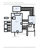
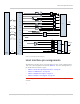
Table Of Contents
- Important Notice
- Safety and Hazards
- Limitation of Liability
- Patents
- Copyright
- Trademarks
- Contact Information
- Revision History
- 1: Introduction
- 2: Technology Overview
- 3: Standards Compliance
- 4: Electrical Specifications
- 5: RF Specifications
- 6: Power
- 7: Software Interface
- 8: Mechanical and Environmental Specifications
- 9: Regulatory and Industry Approvals
- A: Antenna Specification
- B: Design Checklist
- C: Testing
- D: Packaging
- E: References
- F: Acronyms
- Index

Rev 4 Sep.11 Proprietary and Confidential - Contents subject to change 23
4
4: Electrical Specifications
The system block diagram in Figure 4-1 represents the MC7750
module integrated into a host system. The module includes the
following interfaces to the host:
• Power — Supplied to the module by the host.
• W_DISABLE_N — Active low input from a hardware switch to the
MC7750 that disables the main RF radio.
• WLAN_LED_N — Active-low LED drive signal provides an
indication of RADIO ON state, either WAN or GPS.
• Antenna — Three U.FL RF connectors (two for Rx / Tx, and one for
GPS). For details, see RF Specifications on page 37.
Note that GPS can use either the dedicated GPS port, or the
diversity/
MIMO port. GLONASS is supported only on the
dedicated GPS port.
• SIM — Supported through the interface connector. The SIM
cavity / connector must be placed on the host device for this
feature.
• USB — Interface to the host for data, control, and status infor-
mation.
• GPIO — Six GPIOs reserved for future use.
The MC7750 has two main interface areas — the host I/O connector
and the
RF ports. Details of these interfaces are described in the
sections that follow.