
User's Manual


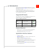
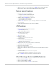
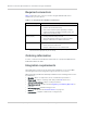
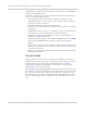
Table Of Contents
- Important Notice
- Safety and Hazards
- Limitation of Liability
- Patents
- Copyright
- Trademarks
- Contact Information
- Revision History
- 1: Introduction
- 2: Technology Overview
- 3: Standards Compliance
- 4: Electrical Specifications
- 5: RF Specifications
- 6: Power
- 7: Software Interface
- 8: Mechanical and Environmental Specifications
- 9: Regulatory and Industry Approvals
- A: Antenna Specification
- B: Design Checklist
- C: Testing
- D: Packaging
- E: References
- F: Acronyms
- Index

Product Technical Specification & Customer Design Guidelines
18 Proprietary and Confidential - Contents subject to change 2400074
Required connectors
Tab l e 1-2 describes the connectors used to integrate AirPrime MC-series
modules into your host device.
Ordering information
To order, contact the Sierra Wireless Sales Desk at +1 (604) 232-1488 between
8
AM and 5 PM Pacific Time.
Integration requirements
Sierra Wireless provides, in the document suite, guidelines for successful Mini
Card integration and offers integration support services as necessary.
When integrating the MC7750 PCI-Express Mini Card, the following items need to
be addressed:
• Mounting—Effect on temperature, shock, and vibration performance
• Power supply—Impact on battery drain and possible RF interference
• Antenna location and type—Impact on RF performance
• Regulatory approvals—As discussed in Regulatory and Industry Approvals on
page 59.
• Service provisioning—Manufacturing process
• Software—As discussed in Software Interface on page 51.
• Host Interface, compliance with interface voltage levels
Table 1-2: Required host-module connectors
1
1. Manufacturers/part numbers are for reference only and are subject to change. Choose
connectors that are appropriate for your own design.
Connector type Description
RF cables • Mate with Hirose U.FL connectors
(model U.FL #CL331-0471-0-10)
• Two or three connector jacks, depending on module
support for diversity and GPS functionality. (Note: The
UDK has two connector jacks.)
EDGE (52-pin) • Industry-standard mating connector
• Some manufacturers include Tyco, Foxconn, Molex
• Example: UDK board uses Molex 67910-0001
SIM • Industry-standard connector. Type depends on how host
device exposes the SIM socket
• Example: UDK board uses ITT CCM03-3518