Product Technical Specification & Customer Design Guidelines AirPrime MC7750 2400074 Rev 4 Distribution under NDA only Contents subject to change
Preface Important Notice Due to the nature of wireless communications, transmission and reception of data can never be guaranteed. Data may be delayed, corrupted (i.e., have errors) or be totally lost.
Product Technical Specification & Customer Design Guidelines Patents This product may contain technology developed by or for Sierra Wireless Inc. This product includes technology licensed from QUALCOMM® 3G. This product is manufactured or sold by Sierra Wireless Inc. or its affiliates under one or more patents licensed from InterDigital Group. Copyright ©2011 Sierra Wireless. All rights reserved. Trademarks AirCard® and Watcher™ are registered trademarks of Sierra Wireless.
Preface Revision History Revision number Release date Changes 1 August 2010 Initial release. 2 January 2011 Resolved most TBDs. Removed references to dial-up networking. Updated Figure 4-1, System block diagram, on page 24; Figure 4-2, Expanded RF block diagram, on page 25; Figure 8-2, Dimensioned view, on page 54.
Product Technical Specification & Customer Design Guidelines 6 Proprietary and Confidential - Contents subject to change 2400074
Contents Introduction . . . . . . . . . . . . . . . . . . . . . . . . . . . . . . . . . . . . . . . . . . . . . . . . . . . . 15 Supported RF bands . . . . . . . . . . . . . . . . . . . . . . . . . . . . . . . . . . . . . . . . . . 15 Physical features . . . . . . . . . . . . . . . . . . . . . . . . . . . . . . . . . . . . . . . . . . . . . 15 Application interface features . . . . . . . . . . . . . . . . . . . . . . . . . . . . . . . . . . . . 15 Packet mode features . . . . . . . . . . . . . . . . . . . .
Product Technical Specification & Customer Design Guidelines SIM interface . . . . . . . . . . . . . . . . . . . . . . . . . . . . . . . . . . . . . . . . . . . . . . . . 30 SIM implementation . . . . . . . . . . . . . . . . . . . . . . . . . . . . . . . . . . . . . . . . . 32 Control interface (Signals) . . . . . . . . . . . . . . . . . . . . . . . . . . . . . . . . . . . . . . 33 W_DISABLE_N — Wireless disable . . . . . . . . . . . . . . . . . . . . . . . . . . . . 33 WLAN_LED_N — LED output . . . . . .
Contents Power interface . . . . . . . . . . . . . . . . . . . . . . . . . . . . . . . . . . . . . . . . . . . . . . 49 Power ramp-up . . . . . . . . . . . . . . . . . . . . . . . . . . . . . . . . . . . . . . . . . . . . 49 Power-up timing . . . . . . . . . . . . . . . . . . . . . . . . . . . . . . . . . . . . . . . . . . . . 49 Power supply noise . . . . . . . . . . . . . . . . . . . . . . . . . . . . . . . . . . . . . . . . . 50 SED (Smart Error Detection) . . . . . . . . . . . . . . . . . . . . . . . .
Product Technical Specification & Customer Design Guidelines Acceptance testing . . . . . . . . . . . . . . . . . . . . . . . . . . . . . . . . . . . . . . . . . . . 71 Acceptance test requirements . . . . . . . . . . . . . . . . . . . . . . . . . . . . . . . . . 72 Acceptance test procedure . . . . . . . . . . . . . . . . . . . . . . . . . . . . . . . . . . . 72 Certification testing . . . . . . . . . . . . . . . . . . . . . . . . . . . . . . . . . . . . . . . . . . . 72 Production testing . . . . . . . .
List of Tables Table 1-1: Supported RF bands . . . . . . . . . . . . . . . . . . . . . . . . . . . . . . . . . . . . 15 Table 1-2: Required host-module connectors . . . . . . . . . . . . . . . . . . . . . . . . . . 18 Table 3-1: Standards compliance . . . . . . . . . . . . . . . . . . . . . . . . . . . . . . . . . . . 21 Table 4-1: Connector pin assignments . . . . . . . . . . . . . . . . . . . . . . . . . . . . . . . 26 Table 4-2: Power and ground specifications . . . . . . . . . . . . . . . . . . . . . .
Product Technical Specification & Customer Design Guidelines Table C-1: Test settings — Receive path. . . . . . . . . . . . . . . . . . . . . . . . . . . . . . 78 Table C-2: Extended AT commands . . . . . . . . . . . . . . . . . . . . . . . . . . . . . . . . . 82 Table F-1: Acronyms and definitions. . . . . . . . . . . . . . . . . . . . . . . . . . . . . . . . .
List of Figures Figure 4-1: System block diagram . . . . . . . . . . . . . . . . . . . . . . . . . . . . . . . . . . . 24 Figure 4-2: Expanded RF block diagram . . . . . . . . . . . . . . . . . . . . . . . . . . . . . . 25 Figure 4-3: SIM application interface . . . . . . . . . . . . . . . . . . . . . . . . . . . . . . . . . 31 Figure 4-4: SIM card contacts (contact view) . . . . . . . . . . . . . . . . . . . . . . . . . . 31 Figure 4-5: Recommended wireless disable connection . . . . . . . . . . . . . . .
Product Technical Specification & Customer Design Guidelines 14 Proprietary and Confidential - Contents subject to change 2400074
1 1: Introduction The Sierra Wireless MC7750 PCI Express Mini Card is a compact, lightweight, wireless LTE- and CDMA-based modem, designed to be Verizon Wireless certified. The MC7750 provides LTE, CDMA, and GPS connectivity for portable and handheld computers, point-of-sale devices, telemetry products and other machine-to-machine and vertical applications over several radio frequency bands.
Product Technical Specification & Customer Design Guidelines • WMC DLL support for Verizon Wireless PC-OEM (Windows)OMA DM (Open Mobile Alliance Device Management)FOTA (Firmware Over The Air) Packet mode features • LTE data rates (category 3, MIMO) · 100 Mbps DL within 20 MHz bandwidth · 50 Mbps UL within 20 MHz bandwidth • CDMA IS-856 (1xEV-DO Rev. A) data rates · Up to 3.1 Mbps forward channel · Up to 1.
Introduction • Mobile-originated SMS over IMS for LTE / eHRPD Position location (GPS) • Standalone mode • GLONASS support on GPS connector 1 (future release) • DC bias on GPS connector 1 to support external active GPS antenna Warranty and support The MC7750 offers the following support features: • Standard 1-year warranty • Enabling software (drivers, SDK, etc.
Product Technical Specification & Customer Design Guidelines Required connectors Table 1-2 describes the connectors used to integrate AirPrime MC-series modules into your host device. Table 1-2: Required host-module connectors 1 Connector type RF cables EDGE (52-pin) SIM Description • Mate with Hirose U.FL connectors (model U.FL #CL331-0471-0-10) • Two or three connector jacks, depending on module support for diversity and GPS functionality. (Note: The UDK has two connector jacks.
2 2: Technology Overview LTE LTE (Long Term Evolution) is a 4th-generation wireless standard. The 3GPP Release 8 specification outlines the features and requirements. Key features include. • Peak data rate: · 100 Mbps DL within 20 MHz bandwidth (Peak DL data rate in 10 MHz bandwidth: 70 Mbps (approx.) for Cat 3 device) · 50 Mbps UL within 20 MHz bandwidth Actual throughput is dependent on the network configuration, bandwidth assigned to the UE, the number of users, and RF signal conditions.
Product Technical Specification & Customer Design Guidelines eHRPD (Enhanced High Rate Packet Data) is an enhancement of 1xEV-DO that enables LTE to CDMA handover. To optimize for data, there are some fundamental characteristics and differences between 1X and 1xEV-DO, including: • The network has dedicated spectrum (1.
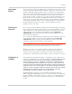
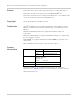
3 3: Standards Compliance The MC7750 Mini Card complies with the mandatory requirements described in the following standards. The exact set of requirements supported is carrier-dependent. Table 3-1: Standards compliance Technology Rev 4 Sep.11 Standards LTE • 3GPP Release 8 CDMA • TIA/EIA/IS-2000.1 through .6. cdma2000® Standards for Spread Spectrum Systems. Release 0. April 2000 • TIA/EIA/IS-2000.1-1 through .6-1. cdma2000® Addendum 1. April 2000 • TIA/EIA/IS-2000.1-2 through .6-2.
Product Technical Specification & Customer Design Guidelines 22 Proprietary and Confidential - Contents subject to change 2400074
4 4: Electrical Specifications The system block diagram in Figure 4-1 represents the MC7750 module integrated into a host system. The module includes the following interfaces to the host: • Power — Supplied to the module by the host. • W_DISABLE_N — Active low input from a hardware switch to the MC7750 that disables the main RF radio. • WLAN_LED_N — Active-low LED drive signal provides an indication of RADIO ON state, either WAN or GPS. • Antenna — Three U.
Product Technical Specification & Customer Design Guidelines VCTCXO TCXO_RTR VCTCXO_DFF RF BLOCK PA_BOOST_EN VGA_MONITOR VGA_UMTS_MONITOR MPM_GPIO_2 PCB ID PCB_ID_1 PCB_ID_0 GPIO55 GPIO8 GPIO56 TCXO_EN PM_INT_N MDM9600 GPIO57 USIM XTAL_19M_IN GPIO_3 GPIO69 MFG_MODE2_N GPIO_6 GPIO25 GPIO24 HSUSB GPIO23 GPIO102 INTERFACE CONNECTOR GPIO_5 MFG_MODE1_N WLAN_LED_N GPIO_4 GPIO70 MFG_MODE0_N VCC_3.
Electrical Specifications TX_LB2 PRX_LB2 TX_LB1 B13 PA B13 BC0 + B5 PA BC0+B5+GSM850 SP2T PRX_LB1 B8+GSM900 PRX_I TX_LB3 B8 PA PRX_Q PRX_MB2 BC1 + B2 RF Main Connector TX_MB3 PRX_MB1 DAC_REF TX_I TX_MB4 BC1/B2 PA SP10T B1 B1d B1 PA TX_Q DRX_MB1 GSM1800 + GSM1900 Jammer Det GSM850/900 TX_LB4 TCXO PA RTR_SSB GSM1800/1900 TX_MB1 Power Det DRX_I DRX_Q DRX_LB1 DRX_LB2 B13d B13 BC0d + B5d + B8d BC0/B5 SP2T B8 DRX_MB2 RF Diversity/GPS Connector 2 SP5T BC1d + B2d Diplexer BC
Product Technical Specification & Customer Design Guidelines Note: The following table describes the internal structure of the module. GPIO pins are reserved for future use. For applications not requiring GPIO functionality, leave these pins not connected on the host. Table 4-1: Connector pin assignments 1 Pin Signal name Pin type 2 Description Direction to module Voltage levels (V) Active state Min Typ Max 1 NC - No connect Reserved for future use. - - - - - 2 VCC V 3.
Electrical Specifications Table 4-1: Connector pin assignments 1 (Continued) Pin 14 Signal name USIM_RST Pin type - 2 Description SIM Reset Direction to module Output Voltage levels (V) Active state Min Typ Max Low 0 - 0.45 High 2.55 (3V SIM) - 3.0 (3V SIM) 1.35 (1.8V SIM) 1.8 (1.8V SIM) 15 GND V Ground Input Power - 0 - 16 GPIO2 - General purpose I/O Input high - 1.17 1.80 2.10 Input low - -0.3 - 0.63 Output high - 1.35 - 1.80 Output low - 0 - 0.
Product Technical Specification & Customer Design Guidelines Table 4-1: Connector pin assignments 1 (Continued) Pin Signal name Pin type 2 Description Direction to module Voltage levels (V) Active state Min Typ Max 37 GND V Ground Input Power - 0 - 38 USB_D+ - USB data positive Input/Output Differential - - - 39 VCC V 3.3 V supply Input Power 3.0 3.3 3.6 40 GND V Ground Input Power - 0 - 41 VCC V 3.3 V supply Input Power 3.0 3.3 3.
Electrical Specifications Power supply The host provides power to the MC7750 through multiple power and ground pins as summarized in Table 4-2. The host must provide safe and continuous power at all times; the module does not have an independent power supply, or protection circuits to guard against electrical issues. Table 4-2: Power and ground specifications Name Pins Specification Min VCC 2, 24, 39, 41, 52 Voltage range See Table 4-1 on page 26.
Product Technical Specification & Customer Design Guidelines be characterized by the OEM. Note that throughput will be reduced and may vary significantly based on packet size, host interface, and firmware revision. Sierra Wireless does not recommend using this device in USB full speed mode. User-developed drivers If you will be developing your own USB drivers, see [5] AirCard / AirPrime USB Driver Developer’s Guide (Doc# 2130634). SIM interface The module supports one SIM (Subscriber Identity Module) (1.
Electrical Specifications USIM_PWR 4.7uF X5R typ 0.1uF (Optional. Locate near the SIM socket) 15 k - 30 k Located near SIM socket (Optional. Locate near the SIM socket) 47 pF, 51 USIM_CLK (C1) (C3) USIM_DATA (C7) USIM_RST (C2) USIM_GND (C5) SIM card connector AirPrime embedded module Located near SIM socket.
Product Technical Specification & Customer Design Guidelines SIM implementation Note: For interface design requirements, refer to: (2G) 3GPP TS 51.010-1, section 27.17, or (3G) ETSI TS 102 230 V5.5.0, section 5.2. 32 When designing the remote SIM interface, you must make sure that SIM signal integrity is not compromised.
Electrical Specifications Control interface (Signals) The MC7750 provides signals for: • Power control of the module from the host • LED driver output These signals are summarized in Table 4-5 and paragraphs that follow. Table 4-5: Module control signals Name Pin Description Type 1 W_DISABLE_N 20 Wireless disable (Main RF) PU WLAN_LED_N 42 LED driver O 1.
Product Technical Specification & Customer Design Guidelines WLAN_LED_N — LED output The module drives the LED output according to [11] PCI Express Mini Card Electromechanical Specification Revision 1.2, as described in Table 4-6 (below). If desired, LED behavior can be configured using AT!LEDCTRL. Table 4-6: LED states (Default behavior) LED behavior !LEDCTRL index State Period (s) On Off Description Off 0 0% 100% Module is not powered.
Electrical Specifications Digital interface The MC7750 Mini Card provides the general purpose digital I/O (GPIO) signals listed in Table 4-7: • By default, all GPIO pins are set as inputs. • Voltage should not be applied until > 1s after VCC is applied to the minicard. • GPIO pins are available for OEM-defined purposes but may, in future firmware releases, be allocated by Sierra Wireless for specific functionality.
Product Technical Specification & Customer Design Guidelines 36 Proprietary and Confidential - Contents subject to change 2400074
5 5: RF Specifications The MC7750 includes three RF connectors for use with host-supplied antennas: • Main RF connector — Rx / Tx path • GPS connector 1 — Standalone GPS • Diversity / MIMO / GPS connector 2 — Diversity, MIMO, or GPS The module does not have integrated antennas.
Product Technical Specification & Customer Design Guidelines Antenna and cabling When selecting the antenna and cable, it is critical to RF performance to match antenna gain and cable loss. Note: For detailed electrical performance criteria, see Appendix A: Antenna Specification on page 65.
RF Specifications Note: A diversity antenna is used to improve connection quality and reliability through redundancy. Because two antennas may experience difference interference effects (signal distortion, delay, etc.), when one antenna receives a degraded signal, the other may not be similarly affected. Ground connection When connecting the module to system ground: • Prevent noise leakage by establishing a very good ground connection to the module through the host connector.
Product Technical Specification & Customer Design Guidelines The severity of this interference depends on the closeness of the other antennas to the module’s antenna. To determine suitable locations for each wireless device’s antenna, thoroughly evaluate your host device’s design. Host-generated RF interference All electronic computing devices generate RF interference that can negatively affect the receive sensitivity of the module.
RF Specifications Note that antenna impedance affects radiated emissions, which must be compared against the conducted 50-ohm emissions baseline. (AirPrime embedded modules meet the 50-ohm conducted emissions requirement.) Radiated sensitivity measurement A wireless host device contains many noise sources that contribute to a reduction in Rx performance.
Product Technical Specification & Customer Design Guidelines • Inter-RAT and inter-frequency cell reselection and handover between supported frequency bands Table 5-1: LTE frequency band support Band Frequencies Band 13 Tx: 777–787 MHz Rx: 746–756 MHz Table 5-2: LTE bandwidth support 1 Band 1.4 MHz 3 MHz 5 MHz 10 MHz 15 MHz 20 MHz 2 2 Band 13 1. Table contents are derived from 3GPP TS 36.521-1 v9.4.1, table 5.4.2.1-1. 2.
RF Specifications Table 5-5: Conducted Rx (Receive) sensitivity — CDMA bands Conducted Rx sensitivity (dBm) CDMA bands Typical Worst case CDMA 1x 0.5% FER -107.5 -104.0 EVDO rev A 0.5% PER -109.5 -105.5 PCS (1900 MHz) Table 5-6: Conducted Tx (Transmit) power tolerances Parameter Conducted transmit power (dBm) 1 Notes LTE +23 dBm 1dB LTE, Band 13 CDMA +24 dBm 1dB CDMA Band Class 0 (Cellular) CDMA Band Class 1 (PCS) +23.5 dBm 1dB (channel 1175) +24 dBm 1dB (other channels) 1.
Product Technical Specification & Customer Design Guidelines Table 5-7: GPS specifications (Continued)1 Parameter/feature Description Sensitivity Tracking2: -161 dBm Acquisition3 (Assisted, non-LTE): -158 dBm Acquisition (Assisted, LTE): -153 dBm Acquisition (Standalone): -145 dBm Operational limits Altitude <6000 m or velocity <100 m/s (Either limit may be exceeded, but not both.) 1. All values are preliminary. 2.
6 6: Power Power consumption Note: All specifications in these tables are preliminary, based on chipset published expectations. Power consumption measurements in the tables below are for the MC7750 Mini Card module connected to the host PC via USB. The module does not have its own power source and depends on the host device for power. For a description of input voltage requirements, see Power supply on page 29.
Product Technical Specification & Customer Design Guidelines Table 6-2: CDMA DC power consumption (+3.3V) Description Bands IS-2000 1X Data current PCS Cellular IS-856 1xEV-DO Revision 0 Data current PCS Cellular IS-856A 1xEV-DO Revision A Data current PCS Cellular Maximum peak current – operational Typ Max Units Notes / configuration 366 - mA SO32, RC3 (Fwd) / RC3 (Rvs), 153.6 kbps (Fwd) / 76.8 kbps (Rvs), CDG Urban Profile, USB active 423 - mA SO32, RC3 (Fwd) / RC3 (Rvs), 153.
Power Table 6-4: Miscellaneous DC power consumption 1 Current Signal Description Typ Unit Notes / configuration Max Module OFF leakage current 490 830 A Full operating temperature range USB active current 18 25 mA High speed USB connection, CL = 50 pF on D+ and D- signals VCC Inrush current GPS signal connector Active bias on GPS port 750 3000 mA 3.3 (100 mA) V • Assumes power supply turn on time > 100µs • Dependent on host power supply rise time.
Product Technical Specification & Customer Design Guidelines Host is powered Module is powered USB interface active RF enabled Table 6-5: Module power states (Continued) Off • • • Host keeps module powered off by driving W_DISABLE_N low Module draws minimal current See W_DISABLE_N — Wireless disable on page 33 for more information.] Disconnected • Host power source is disconnected from the module and all voltages associated with the module are at 0 V.
Power current_vcc < VOLT_LO_WARN current_temp > TEMP_HI_WARN Normal mode current_vcc > VOLT_LO_NORM current_temp < TEMP_HI_NORM current_vcc > VOLT_LO_NORM current_temp <= TEMP_HI_NORM current_vcc > VOLT_HI_CRIT current_temp < TEMP_LO_CRIT current_vcc < VOLT_HI_NORM current_temp > TEMP_NORM_LO Normal mode Low supply voltage warning or High temperature warning current_vcc < VOLT_LO_CRIT current_temp > TEMP_HI_CRIT Low power mode Handled by Power State state machine.
Product Technical Specification & Customer Design Guidelines Power supply noise Noise in the power supply can lead to noise in the RF signal. The power supply ripple limit for the module is no more than 200 mVp-p 1 Hz to 100 kHz. This limit includes voltage ripple due to transmitter burst activity. Additional decoupling capacitors can be added to the main VCC line to filter noise into the device. SED (Smart Error Detection) The module uses a form of SED to track premature modem resets.
7 7: Software Interface Support tools The MC7750 is compatible with the following support tools from Sierra Wireless and authorized third parties: • Firmware update utilities from Sierra Wireless • Sierra Wireless Product Support Tool (SW-PST) • CDMA Air Interface Tool (CAIT) from QUALCOMM • QXDM from QUALCOMM • QUALCOMM Product Support Tool (QPST) USB interface The device supports the Qualcomm QMI interface.
Product Technical Specification & Customer Design Guidelines 52 Proprietary and Confidential - Contents subject to change 2400074
8: Mechanical and Environmental Specifi- 8 cations The MC7750 module complies with the mechanical and environmental specifications in Table 8-1. Final product conformance to these specifications depends on the OEM device implementation.
Product Technical Specification & Customer Design Guidelines Device views Top view Top view Bottom view Bottom view Figure 8-1: Top and bottom views Figure 8-2: Dimensioned view 54 Proprietary and Confidential - Contents subject to change 2400074
Mechanical and Environmental Specifications Labeling MC77XX IMEI # 352678011234569 FPPDDDYNNNNHH BB ||||||||||||||||||||||||||||||||||| FCC ID: N7Nxxxxxx PRODUCT OF CHINA Figure 8-3: Unit label Note: The displayed label is an example only. The production label will vary by SKU.
Product Technical Specification & Customer Design Guidelines Thermal considerations Embedded modules can generate significant amounts of heat that must be dissipated in the host device for safety and performance reasons. Transmitter Receiver Baseband 1 Baseband 2 Pin 1 Pin 1 Top Bottom Figure 8-4: Shield locations The amount of thermal dissipation required depends on: • Supply voltage — See Chapter 6: Power on page 45 for details of max power dissipation for various operating modes.
Mechanical and Environmental Specifications Module integration testing When testing your integration design: • Test to your worst case operating environment conditions (temperature and voltage) • Test using worst case operation (transmitter on 100% duty cycle, maximum power) • Monitor temperature at all shield locations. Attach thermocouples to the areas indicated in Figure 8-4 on page 56 (Transmitter, Baseband 1, Receiver, Baseband 2).
Product Technical Specification & Customer Design Guidelines 58 Proprietary and Confidential - Contents subject to change 2400074
9 9: Regulatory and Industry Approvals This module is designed to and, upon commercial release, will be certified to meet carrier requirements (e.g. Verizon Wireless).
Product Technical Specification & Customer Design Guidelines POWERED OFF. Otherwise, the MC7750 modem can transmit signals that could interfere with this equipment. In an aircraft, the MC7750 modem MUST BE POWERED OFF. Otherwise, the MC7750 modem can transmit signals that could interfere with various onboard systems and may be dangerous to the operation of the aircraft or disrupt the cellular network. Use of a cellular phone in an aircraft is illegal in some jurisdictions.
Regulatory and Industry Approvals Note: If this module is intended for use in a portable device, you are responsible for separate approval to satisfy the SAR requirements of FCC Part 2.1093 and IC RSS-102. OEM integration Application of regulatory guidelines Because ‘near-body’ devices (handhelds, laptops, tablets, scanners, etc.
Product Technical Specification & Customer Design Guidelines The review process between the OEM module integrator and the preferred regulatory test lab is a crucial step in determining the appropriate device classification, as it is impractical for Sierra Wireless to define all possible combinations of design features, antennas, physical configurations, and usemodels. 1. Perform a device review with the preferred regulatory test lab to confirm device classification. 2.
Regulatory and Industry Approvals • All antennas in the final product must be at least 20 cm from users and nearby persons. OEM product instruction manual content Consistent with §2.909(a), the following text must be included within the user’s manual or operator instruction guide for the final commercial product. (OEMspecific content is displayed in italics.) Operating Requirements and Conditions The design of (Product Name) complies with U.S.
Product Technical Specification & Customer Design Guidelines 64 Proprietary and Confidential - Contents subject to change 2400074
A A: Antenna Specification This appendix describes recommended electrical performance criteria for main path, diversity path, and GPS antennas used with AirPrime embedded modules. The performance specifications described in this section are valid while antennas are mounted in the host device with antenna feed cables routed in their final application configuration. Note: Antennas should be designed before the industrial design is finished to make sure that the best antennas can be developed.
Product Technical Specification & Customer Design Guidelines Table A-1: Antenna requirements (Continued) a Parameter Requirements Envelope correlation coefficient between Ant1 and Ant2 Comments < 0.4 on 730–960 MHz band < 0.3 on 1800–1990 MHz and 2110–2170 MHz bands < 0.
Antenna Specification Recommended GPS antenna specifications Table A-2: GPS standalone antenna requirements Parameter Frequency range Field of view (FOV) Requirements • 1575.42 MHz ±2 MHz minimum • 1565–1606 MHz recommended • Omni-directional in azimuth • -45° to +90° in elevation Comments Polarization (average Gv/Gh) > 0 dB Vertical linear polarization is sufficient.
Product Technical Specification & Customer Design Guidelines • Any metallic part of the antenna system that is exposed to the outside environment needs to meet the electrostatic discharge tests per IEC61000-42 (conducted discharge +8kV). • The functional requirements of the antenna system are tested and verified while the embedded module’s antenna is integrated in the host device.
B B: Design Checklist This chapter provides a summary of the design considerations mentioned throughout this guide. This includes items relating to the power interface, RF integration, thermal considerations, cabling issues, and so on. Note: This is NOT an exhaustive list of design considerations. It is expected that you will employ good design practices and engineering principles in your integration.
Product Technical Specification & Customer Design Guidelines Table B-1: Hardware integration design considerations (Continued) Suggestion Section where discussed SIM implementation on Provide ESD protection for the SIM connector at the exposed contact point (in particular, the CLK, VCC, IO, and RESET lines). page 32 Keep very low capacitance traces on the USIM_DATA and USIM_CLK signals.
C C: Testing Note: All AirPrime embedded modules are factory-tested to ensure they conform to published product specifications. Developers of OEM devices integrating Sierra Wireless AirPrime embedded modules should include a series of test phases in their manufacturing process to make sure that their devices work properly with the embedded modules.
Product Technical Specification & Customer Design Guidelines Acceptance test requirements To perform the suggested tests, you require a test system in which to temporarily install the module, and you must be able to observe the test device’s LED indicator. Acceptance test procedure The following is a suggested acceptance testing procedure using Sierra Wireless’ Watcher™ software: Note: You can perform these tests using appropriate AT commands. Test 1: Check power-up and initialization 1.
Testing • Factory Mutual (FM Global — www.allendale.com) • Underwriters Laboratories Inc. (www.ul.com) • CDG (CDMA Development Group — www.cdg.org) • GCF (Global Certification Forum — www.globalcertificationforum.org) outside of North America • PTCRB (PCS Type Certification Review Board — www.ptcrb.com) in North America Production testing Note: Production testing typically continues for the life of the product.
Product Technical Specification & Customer Design Guidelines Suggested production tests Consider the following tests when you design your production test procedures for devices with the AirPrime module installed.
Testing · With one other USB device already connected and assigned to ttyUSB1: (Note: The AT port is the fourth new device — / dev / ttyUSB4.) 6. Make sure your modem is connected and running, and then establish contact with the module: · Windows systems: Use a terminal emulation / communications program such as Microsoft HyperTerminal® to connect over the COM port reserved for AT commands (see listings in Step 5): a. Start HyperTerminal. b. Select File > Connection Description.
Product Technical Specification & Customer Design Guidelines 7. Display the firmware version: · AT!GVER 8. Test the LED — Set the LED in blinking mode using this command, then visually verify that the LED turns off and on: · AT!LEDCTRL 9. Unlock the extended AT command set: · AT!ENTERCND 10. Put the module in diagnostic / factory test mode: · AT!DAFTMACT 11. Communicate with the SIM using +CPIN or +CIMI. When performing RF tests, use a test platform as described in Suggested testing equipment on page 81.
Testing 8. Use the down-arrow key to select Save setup as dfl. 9. Select Exit. Testing CDMA RF Receive path Note: This procedure segment is performed in Step 13 of the Production test procedure on page 74. To test the DUT’s receive path: Note: This procedure describes steps using the Agilent 8648C signal generator — the Rohde & Schwarz SML03 is shown for reference only.
Product Technical Specification & Customer Design Guidelines Note: The dBm value displayed is calculated to reflect the power at the input connector. f. AT!RX2=1 (Turn on diversity receiver.) g. AT!RX2AGC? (Read back the power level, in dBm, from the diversity receiver.) Response examples: · RX2AGC = 0xFFFFFF76 = -84 dBm (Signal generator’s RF port is OFF) · RX2AGC = 0xFFFFFFC6 = -69 dBm typical (Signal generator’s RF port is ON) h. AT!RX=0 (Turn off main receiver.) i.
Testing a. All values offset from actual center channel by +2 MHz b. Channel values shown are at the center of the corresponding bands. To test the DUT’s receive path (or diversity path, while connected to the diversity antenna): Note: This procedure describes steps using the Agilent 8648C signal generator — the Rohde & Schwarz SML03 is shown for reference only. 1. Set up the signal generator: a. Set the amplitude to -70 dBm b. Set the frequency for the band being tested.
Product Technical Specification & Customer Design Guidelines Note: The value measured from the DUT is significantly influenced by the test setup and DUT design (host RF cabling loss, antenna efficiency and pattern, test antenna efficiency and pattern, and choice of shield box). GPS standalone connector test GPS testing should be done on devices that support a dedicated GPS connector.
Testing • Power consumption • Originate and terminate data and voice (if applicable) calls • Cell hand-off • Transmitter and receiver tests • FER (Frame Error Rate) as an indicator of receiver sensitivity / performance • Channel and average power measurements to verify that the device is transmitting within product specifications • RF sensitivity tests • CDMA: · FER testing — Test receiver sensitivity for conditions of minimum cell power.
Product Technical Specification & Customer Design Guidelines Extended AT commands for testing Sierra Wireless provides proprietary AT commands that may help in hardware integration design and testing (these commands are NOT intended for use by end users): • [3] AirPrime MC8xxx Embedded Modules Extended AT Command Reference (Doc# 2130616) • [2] AirCard / AirPrime UMTS Devices Supported AT Command Reference (Doc# 2130617) Some useful commands from these documents for use in hardware integration are liste
Testing Table C-2: Extended AT commands (Continued) Command Rev 4 Sep.
Product Technical Specification & Customer Design Guidelines Table C-2: Extended AT commands (Continued) Command 84 Description !TX Turn transmitter on / off !TXAGC Set desired Tx AGC Proprietary and Confidential - Contents subject to change 2400074
D D: Packaging Sierra Wireless AirPrime Mini Cards are shipped in sealed boxes. The standard packaging (see Figure 4-1), contains a single tray with a capacity of 100 modules . (Note that some SKUs may have custom packaging — contact Sierra Wireless for SKU-specific details.) In the standard packaging, Mini Cards are inserted, system connector first, into the bottom portion (T1) of a two-part tray. all facing the same direction.
Product Technical Specification & Customer Design Guidelines 86 Proprietary and Confidential - Contents subject to change 2400074
E: References This guide deals specifically with hardware integration issues that are unique to AirPrime embedded modules. Web site support For additional documents describing embedded module design, usage, and integration issues (AT command references, integration guides, etc.), visit www.sierrawireless.com/minicard. To obtain access permission, contact your Sierra Wireless account representative. Sierra Wireless documents The following Sierra Wireless documents are available from www.sierrawireless.com.
Product Technical Specification & Customer Design Guidelines [11] PCI Express Mini Card Electromechanical Specification Revision 1.2 [12] Universal Serial Bus Specification, Rev 2.
F: Acronyms Table F-1: Acronyms and definitions Acronym or term Rev 4 Sep.11 Definition 1xEV-DO Single Carrier (1X) EVolution – Data Only. A high-speed standard for cellular packet data communications. Supports Internet connections with data rates up to 3.1 Mbps (downlink from the network) and 1.8 Mbps (uplink to the network). Average data rates are roughly: for Rev. A: 600 1300 kbps (downlink from the network) and 300 400 kbps (uplink to the network); for Rev.
Product Technical Specification & Customer Design Guidelines Table F-1: Acronyms and definitions (Continued) Acronym or term Definition Decibel = 10 x log10 (P1 / P2) P1 is calculated power; P2 is reference power dB Decibel = 20 x log10 (V1 / V2) V1 is calculated voltage, V2 is reference voltage 90 dBm A logarithmic (base 10) measure of relative power (dB for decibels); relative to milliwatts (m).
Acronyms Table F-1: Acronyms and definitions (Continued) Acronym or term Rev 4 Sep.11 Definition GLONASS Global Navigation Satellite System GMSK Gaussian Minimum Shift Keying modulation GND Ground GPRS General Packet Radio Service GPS Global Positioning System A system that uses a series of 24 geosynchronous satellites to provide navigational data.
Product Technical Specification & Customer Design Guidelines Table F-1: Acronyms and definitions (Continued) Acronym or term 92 Definition MEID Mobile Equipment Identifier — The unique second-generation serial number assigned to the minicard for use on the wireless network. MIMO Multiple Input Multiple Output—wireless antenna technology that uses multiple antennas at both transmitter and receiver side. This improves performance.
Acronyms Table F-1: Acronyms and definitions (Continued) Acronym or term Rev 4 Sep.11 Definition RF Radio Frequency RI Ring Indicator roaming A cellular subscriber is in an area where service is obtained from a cellular service provider that is not the subscriber’s provider. RSE Radiated Spurious Emissions RSSI Received Signal Strength Indication SDK Software Development Kit SED Smart Error Detection Sensitivity (Audio) Measure of lowest power signal that the receiver can measure.
Product Technical Specification & Customer Design Guidelines Table F-1: Acronyms and definitions (Continued) Acronym or term 94 Definition TRP Total Radiated Power UDK Universal Development Kit (for PCI Express Mini Cards) UE User Equipment UICC Universal Integrated Circuit Card (Also referred to as a SIM card.
Index Numerics C 1X cable loss antenna, maximum, 37 CAIT support, 51 capacitors with SIM, 32 with XIM_DATA / XIM_CLK, 32 carrier/operator testing, 81 CDMA overview, 20 1xEV-DO overview, 19 3D gain, average gain 3D average (GPS), 67 3GPP compliance LTE, 21 A acceptance tests, 71 accessories, 17 accuracy (GPS), 43 acquisition time (GPS), 43 acronyms and definitions, 89– 94 antenna connection considerations, 37 connectors, 23 custom, design, 38 diversity antenna, disabling, 38 GPS, specifications, recomme
Product Technical Specification & Customer Design Guidelines E humidity specifications, 53 EDGE connector, required, 18 electrical specifications, 23 electrostatic discharge specifications, 53 electrostatic discharge.
Index minicom downloading and installing, 76 module power states, 47– 49 N NAS/AS security, 16 NDIS NIC interface support, 15 NIC interface support, 15 noise leakage, minimizing, 39 RF interference, power supply, 50 O OEM assistance with testing, 81 labeling, 55 operator/carrier testing, 81 ordering information, 18 P packaging, 85 packet mode features, 16 paging procedures, 16 PCB multi-layer, shielding for RF desense, 40 PDN connections, multiple, 16 pin assignments, host interface, 25 PMI, 16 polariza
Product Technical Specification & Customer Design Guidelines shielding module, compliance, 37 reducing RF desense, 40 shock specifications, 53 SIB, 16 signals, 33 WLAN_LED_N, 34 SIM capacitor recommendations, 32 card contacts, 31 clock rate, 32 connector, required, 18 electrical specifications, 32 impedance, connectors, 32 interface, 30 interface diagram, 31 operation, 32 Smart Error Detection detecting module reset, 50 SMS features, 16 Snow 3G/AES security, 16 software interface, 51 specifications electri