H E A D S U P T E C H N O L O G I E S Installation Manual XM Satellite Weather and Radio Wireless Receiver Model No. XMD076A Revision Level: C Revision Date: 06/22/06 Document Control No.: XMD076A-3 File Name: XMD076A-3_C.doc This document contains copyrighted material and confidential trade secret information belonging exclusively to Heads Up Technologies, Inc. Unauthorized use, disclosure, or duplication of any of this material may result in liability under applicable laws.
H E A D S U P T E C H N O L O G I E S Installation Manual XMD076A Important Information CHANGES OR MODIFICATIONS TO THIS DEVICE NOT EXPRESSLY APPROVED BY THE MANUFACTURER COULD VOID THE USERS AUTHORITY TO OPERATE THE EQUIPMENT.
H E A D S U P T E C H N O L O G I E S Installation Manual XMD076A Revision Record Revision Level Description of Changes Author Approved by Release Date - Initial Release JH DJG 9/27/05 A Added Bluetooth antenna specifications and professional installation warning. JH DJG 11/18/05 B Changed Satellite Antenna cable requirements: Added Section 2.4.1 and changed Note 3 in App. B diagram. Added pre-activation information for XM Radio operation. Updated XM Radio phone number.
H E A D S U P T E C H N O L O G I E S Installation Manual XMD076A Table of Contents Section 1.0 Description Page GENERAL INFORMATION .................................................................................................... 1 1.1 EQUIPMENT DESCRIPTION ............................................................................................................. 1 1.2 TECHNICAL SPECIFICATIONS .....................................................................................................
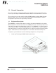
H E A D S U P T E C H N O L O G I E S Installation Manual XMD076A 1.0 General Information This manual provides product description and installation reference information for the Heads Up Technologies XMD076A XM Satellite Weather and Radio Wireless Receiver. This receiver is for use with specific Avidyne XM WX software equipped Multi-Function Displays (MFD’s) only. Please refer to the Avidyne MFD documentation for software configuration requirements and operating instructions. 1.
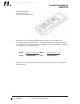
H E A D S U P T E C H N O L O G I E S Installation Manual XMD076A • XMC050 XM Radio Wireless Remote Controller (illustrated here) • Many options of XM Satellite Radio certified antennas are available and manufactured by Comant Industries. Single and combination function antennas are available. For a complete listing of available antennas, contact the Heads Up Technologies sales department at: • Email: info@heads-up.com Web: www.heads-up.
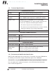
H E A D S U P T E C H N O L O G I E S Installation Manual XMD076A 1.2 Technical Specifications STANDARD FEATURES Display None. User interface through XMC050 controller WX Interface RS232, 115.2Kbaud, No parity, 8-bit, 1 stop bit Audio Interface (Typical) Stereo 600-ohm balanced transformer, 0dBV nominal level, <-50dBV (when muted) to +12dBV (Full volume) Wireless Link Bluetooth Class 2 (low power, 25 Ft. LOS Range) FCC ID # TGVXMSC63.
H E A D S U P T E C H N O L O G I E S Installation Manual XMD076A 2.0 Installation Instructions 2.1 Unpacking and Inspection Verify all ordered parts were received and sustained no shipping damage. Where evidence of shipping damage exists, save the shipping carton and packing material to help substantiate your claim to the shipping company. Retain the original shipping carton and packing material in case you need to ship the unit for service. 2.
H E A D S U P T E C H N O L O G I E S Installation Manual XMD076A 2.3 XMD076A Receiver Installation 2.3.1 Installation Considerations The XMD076A is intended for application as a “sensor” to the MFD, providing a datalink to the weather information transmitted by XM Satellite Radio. The software contained in the XMD076A meets the requirements of RTCA DO-178B, Level E. 2.3.1.
H E A D S U P T E C H N O L O G I E S Installation Manual XMD076A bracket or plate can be fabricated to attach to the aircraft structure, as required, IAW AC 43.13-2A, Chapter 2. The mounting of the XMD076A enclosure must provide a DC bond to airframe ground of 0.003 Ohms or less. 2.3.3 Electrical Interface Wiring Refer to Appendix C for system wiring diagrams and wire type requirements. Wiring is to be performed IAW AC 43.13-1B, Chapter 11.
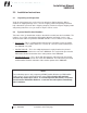
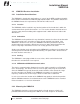
H E A D S U P T E C H N O L O G I E S Installation Manual XMD076A The illustration below is for a headphone jack: NOTE: Use a ground isolated headphone jack where the “sleeve” of the jack is not electrically connected to the aircraft ground. If the audio cable run is less than 10 Ft. from the receiver to the jack, then ground isolation should not be required. The below illustrations show typical connections to aircraft audio panels: 5.
H E A D S U P T E C H N O L O G I E S Installation Manual XMD076A WARNING: The below extension shall be performed by a professional installer and only after determining through analysis or test that this extension is necessary for proper operation. 8. Ground Terminations: Wire ground straps used to terminate cable shields and equipment shall be as short as possible. All bonds shall be 0.003 Ohms or less. 2.3.
H E A D S U P T E C H N O L O G I E S Installation Manual XMD076A 2.4 XM Satellite Antenna Installation Considerations The XMD076A is designed for use with various XM Radio type-certified antennas covering the S-Band from 2.332 GHz to 2.345 GHz. Due to the low signal levels inherent with satellite communications, the following guidelines and recommended practices should be adhered to for the design of the antenna installation: • Install IAW AC 43.13-2A Chapter 3, AC 43.
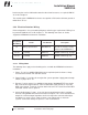
H E A D S U P T E C H N O L O G I E S Installation Manual XMD076A Table 1 - Cable Length Chart RG Type (Mil-C-17) Loss Rating (dB/100-Ft.) @ 2.339GHz Length Range (Ft.) @ 8 - 12dB Loss 142 20.6 38.8 – 58.3 400 23.41 34.2 – 51.3 316 40.87 19.6 – 29.4 178 68.82 11.62 – 17.4 When antennas of other gain values or other cable types are installed, the cable length can be determined using the equation below: Cable Length (Feet) = ( Antenna Gain – 22 Cable Loss Rating (in dB/100-Ft.
H E A D S U P T E C H N O L O G I E S Installation Manual XMD076A • Receive only antennas such as ADF and GPS do not produce interference and require little separation. The XM antenna should be placed as close as possible to these types of antennas to gain separation from transmitters. NOTE: Installation pre-testing is advised if this installation is being performed on several similar aircraft such as a fleet.
H E A D S U P T E C H N O L O G I E S Installation Manual XMD076A 2.5 Weight and Balance A Weight and Balance calculation of the aircraft is required as part of the installation approval process. Following the guidelines as established in AC 43.13-1B, Chapter 10, Section 2, the W/B of the aircraft can be calculated using the weights of the system components listed below. Description Weight (lbs.) XMD076A Receiver 1.7 XMRANT-01 (standard XM Antenna) 0.
H E A D S U P T E C H N O L O G I E S Installation Manual XMD076A 3.0 System Checkout The following XMD076A system-checkout aides are intended to assure proper installation and interfacing to the MFD, antenna and audio system. Familiarize yourself with: • The MFD operational guide for explanations of using the MFD to communicate with the XMD076A. • The XMC050 Controller operations guide. • The audio system configuration to verify the XMD076A audio performs as intended. 3.
H E A D S U P T E C H N O L O G I E S Installation Manual XMD076A 3.2.2 Power System and Initial Test 1. Apply power to the XMD076A receiver and any other system applicable to the MFD or audio equipment. Some installations may include a WX Data power switch and if equipped, toggle to the ON position. The receiver is equipped with an on-board red LED indicator to show the receiver is powered-on. XM WX: The MFD operations manual may be required to continue. 2. Power up the MFD.
H E A D S U P T E C H N O L O G I E S Installation Manual XMD076A • With the XMC050 powered, press the "receiver select" button on the remote (top right button). • Enter 4881 for password, then enter 88. • The display will show “Receiver ID Search”. XMC050 is now searching for available receivers that are in range of the communication link (25 feet). • When a receiver is found, the display will change to “Receiver ID Found” and list the ID number of the receiver.
H E A D S U P T E C H N O L O G I E S Installation Manual XMD076A Note: The “Satellite Radio ID” code must presented to the aircraft owner, who will need it to acquire the subscription service and for other customer service needs with XM Satellite Radio.
H E A D S U P T E C H N O L O G I E S Installation Manual XMD076A 3.3 Ground EMI Check The following procedure is to be performed to verify that no interference is noted through the use of the XMD076A system on other aircraft systems and vice-versa. The operation of the XMD076A system shall not result in NAV flags, constant location lightning strikes on any installed Stormscope, noise on COMM channels, or other phenomena.
H E A D S U P T E C H N O L O G I E S Installation Manual XMD076A 4.0 Factory Service Policies 4.1 Technical Support Technical support or service questions may be submitted to the following: Email: service@heads-up.com Voice: 972-980-4890 Fax: 972-980-4743 A Heads Up Technologies customer support representative will respond as soon as possible. Heads Up Technologies business hours are 8:00 AM to 5:00 PM Central Time, Monday through Friday.
H E A D S U P T E C H N O L O G I E S Installation Manual XMD076A Appendix A Environmental Qualification Forms XMD076A DO-160 Environmental Qualification Form UUT NOMENCLATURE XM Weather / Radio Wireless Receiver, RS232 Type TYPE/MODEL/PART NO. TSO NUMBER XMD076A-01 N/A MANUFACTURER’S SPECIFICATION AND/OR OTHER APPLICABLE SPECIFICATION XMD076A-32, XMD076A-01 Qualification Test Plan MANUFACTURER Heads Up Technologies, Inc, 2033 Chenault Dr.
H E A D S U P T E C H N O L O G I E S Installation Manual XMD076A UUT NOMENCLATURE XM Weather / Radio Wireless Receiver, RS232 Type TYPE/MODEL/PART NO. TSO NUMBER XMD076A-01 N/A MANUFACTURER’S SPECIFICATION AND/OR OTHER APPLICABLE SPECIFICATION XMD076A-32, XMD076A-01 Qualification Test Plan MANUFACTURER Heads Up Technologies, Inc, 2033 Chenault Dr.
H E A D S U P T E C H N O L O G I E S Installation Manual XMD076A UUT NOMENCLATURE XM Radio Wireless Controller TYPE/MODEL/PART NO. TSO NUMBER XMC050-( ) N/A MANUFACTURER’S SPECIFICATION AND/OR OTHER APPLICABLE SPECIFICATION XMC050-32, XMC050 Env. Qualification Test Plan MANUFACTURER Heads Up Technologies, Inc, 2033 Chenault Dr.
H E A D S U P T E C H N O L O G I E S Installation Manual XMD076A Appendix B Mechanical Installation Diagram XMD076A RECEIVER DIMENSIONS XMD076A-3 Rev C, 06/22/06 Information is subject to the restrictions on the title page 22
H E A D S U P T E C H N O L O G I E S Installation Manual XMD076A Appendix C Electrical Installation Diagram XMD076A RECEIVER WIRING XMD076A-3 Rev C, 06/22/06 Information is subject to the restrictions on the title page 23