XT6372R User Guide Version 2.0 188 Camino Ruiz Camarillo, CA 93012 www.xirgotech.com support@xirgotech.
Contents Document Change History .......................................................................................................................... 2 Hardware Specification:.............................................................................................................................. 3 Connectors IO Interface: ............................................................................................................................. 4 Cable Harness Specification: ....................
Document Change History Revision Date 1.0 2.0 4/12/2017 7/21/2017 Changes Initial Release based on XT6350 User Guide_V2 Revised based on TCB notes 2 Sales Engineering support@xirgotech.
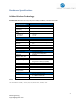
Hardware Specification: Cellular Wireless Technology: Verizon LTE: Bands 4 and 13 (1700/2100 AWS, 700 MHz) - Models: XT6372R Parameter GPS Specification Receiver Receiver tracking sensitivity CEP Accuracy TTFF - Cold Start - Hot Start HW Options: 3-axis Accel. BT/BTLE Last Gasp Back-up Battery Power Requirements D.C.
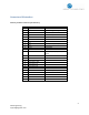
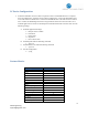
Connectors IO Interface: Main 24-pin Molex Connector (IO Interface): Pin No.
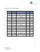
OBD 14-pin Molex connector (OBD2/JBUS/SWC): J1962 OBD2 Pin No. XT6372R Pins XT6372R Pin Description 9 Pin J-Bus 6 Pin J-Bus 6 1 CAN_HS_H C 2 J1708_RXD G B 3 J1708_TXD F A 15 4 L_LINE 10 5 J1850_NEG 2 6 J1850_POS 7 14 8 CAN_HS_L D 3 9 CAN_MS_H 11 10 CAN_MS_L 1 11 SWC_BUS 7 12 K_LINE 5&4 13 GND A E 16 14 Vehicle Power (VBAT) B C 5 Sales Engineering support@xirgotech.
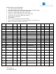
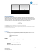
Cable Harness Specification: • • • • • • • • • • • 24-pin Microfit: Molex 43025-2400 Panic SW/LED Button Conn. Molex 43020-0401 (4 pin 2 row female shell) I-Button Conn.: Molex 43640-0201 (2 pin Female Shell) Buzzer Conn.: Molex 43640-0301 (3 pin Female Shell) Garmin Conn. Molex 43020-1001 (10 pin 2 row female shell) Garmin pins 2 and 4 looped-in (black wire, 26 AWG) Molex male pins: 43031-0002 Total length: 5 ft. Pins 1, 3, and 5 are 18 AWG, All others are 24 AWG.
21 White 60 in. 20 OWB2 22 Purple 60 in. 20 Ext. ADC 23 Black 7 in. 20 Spare GND 24 Blue/Green 7 in.
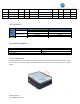
PC Device Configuration: a. A RS-232 to USB TTL converter cable is required to connect an XT6372R device to a computer for local configuration. Serial Port # 2 is used for configuration. Connect the XT6372R Tx wire to the TTL converter cable Rx wire. Connect the XT6372R Rx wire to the TTL converter cable Tx wire. Connect the XT6372R ground wire to the ground wire of the TTL converter cable. Use a terminal application to connect to the COM port associated with the TTL converter cable.
Park Time X Virtual Odometer X Quick Fence X Device Diagnostics X Motion X X Accelerometer Geo-Zones 50 Circular Back Up Battery 250mAh Communication Protocol TCP, UDP , UDPwACK Firmware Download FTP Device Configuration The XT6372R is a full-feature device based on a platform that allows rapid customization by market and application requirements. The XT6372R series offers highly configurable firmware which allows full control of device reporting behavior.
Important notes on Scripting: 1. 2. 3. 4. 5. 6. 7. 8. Each Trigger Block has one Trigger. The Trigger must test true for an action to occur. A test is usually made of one comparison. See Comparison table. Each Trigger Block can contain unlimited Conditional Action Blocks. Trigger Blocks and Conditional Action block will use the following when building a script: a. System Values b. Events c. Special Functions d. Numbers Each Conditional Action Block may optionally contain one Conditional Action Block Test.
COMPARISONS TABLE: COMPARISON InRange(, , ) NotInRange(, , ) Eq(, ) NotEq(, ) Gt(, ) Lt(, ) GtEq(, ) LtEq(, ) DESCRIPTION True when argument a is between argument b and argument c (inclusive) True when a is less than b or a is greater than c. b must be less than c. True when a equals b. True when a is not equal to b. True when a is greater than b. True when a is less than b. True when a is greater than/equal to b. True when a is less than/equal to b.
Parameter File The parameter file is the setting for all of the XT6372R hardware peripherals, network behavior, and inputs to core functionality of the XT6372R.
Messages How to create a Message The XT6372R custom message allows users to select what fields of data to be sent in a message when triggered. A message can contain up to 40 data fields and you can have up to 128 different messages.
▪ recipe_hex_string -" fe0401031213" • RecipeID • Number of fields 04 • Field 0 is Packet ID 01 • Field 1 is DeviceID 03 • Field 3 is Hdop 12 • Field 4 is Numsats 13 fe Decoding a Message Knowing the Reason Code and Packet Id you will know how to parse your data. These 2 fields will let you know what triggered the message, what data is being sent, and in what order you’re receiving the data. Refer to Appendix F for a complete list of Fields available.
pcr[] "" is in the range 0 - 127 "" is a quoted string of hexadecimal bytes (represented by two ascii characters) String format: "...
Acknowledgements Currently the XT6372R supports a simple acknowledgement consisting of four bytes (88-88-xx-xx) where xx-xx is the packet serial number. You will want to send the 88-88 header and return the serial number of the packet sent to you, in the third and fourth byte. Therefore, the XIRGO unit will only accept an acknowledgement payload of 88-88-01-04 for a packet sent with packet serial number 260 (hex 01-04). 16 Sales Engineering support@xirgotech.
Appendix A SYSTEM VALUES VALUE UnixTime GPSLat GPSLon GPSAlt GPSHeading GPSSpeed Inputs Outputs DriverId1 DriverId2 OdomDelta DESCRIPTION Seconds since midnight Jan 1, 1970. Degrees of latitude (unit 0.000001 degree) Degrees of longitude (unit 0.000001 degree) Height above sea level (unit 0.1 meter) Heading of travel (unit 0.1 degree) 2D speed in km/hr.
Appendix B EVENT TimerExpired() EVENT TABLE DESCRIPTION Evaluates to 1 when timer is expired, otherwise 0 Evaluates to 1 when a user event has been injected into interpreter, otherwise 0 Use :xrmsg to inject a message into interpreter.
Appendix C SPECIAL FUNCTION TABLE Special Function UserVar8() UserVar16() UserVar32() FlagIsSet() GeofenceState() InputState() SystemState() Description Evaluates to value stored in user variable Evaluates to value stored in user variable Evaluates to value stored in user variable Evaluates to 1 when flag is set, otherwise 0 Evaluates to: -1= is not configured 0=outside fence 1=inside fence Evaluates to 1 when input is high/when condition is true, o
Appendix D ACTIONS TABLE Action Reset Device Reset Modem Reset GPS Turn Off GPS Turn On GPS Set User Variable Syntax ResetDevice() ResetModem() ResetGPS() TurnOffGPS() TurnOnGPS() SetUserVar(, , ) Adjust User Variable type is in the range 0 - 2 where: 0 = 8bit variable 1 = 16bit variable 2 = 32bit variable index is in the range: 0 - 15 for 8bit variables 0 - 7 for 16bit variables 0 - 7 for 32bit variables value is in the range: -128 to 127 for 8bit variables -32768 to 32767 for 16bi
ACTION Build And Send Msg SYNTAX , , , ) Clear Log Enter Deep Sleep packet_id is in the range 0 – 255. reason_code is in the range 0 - 255. destination_id is in the range 0 - 9.
Flash Output FlashOutput(, ) Clear Driver Ids Device Check In index is in the range 0 - 3. blink_rate is in the range 1 - 65535Hz. ClearDriverIds() CheckInNow() 22 Sales Engineering support@xirgotech.
Appendix E Acceleration event thresholds Accelerometer report correction APNs Crash event params Debounce settings Destination ECU_Thresholds Flag save mask Garmin Blacklist Geofence Input default polarity Ignition sense MIP/SIP Control (TBD) Motion sensitivity PARAMTER TABLE 8 aet 4 1 arc 1 4 1 6 10 1 1 16 50 4 1 1 1 apn cep idb dst vth fsm gbl gfn idp ign mip mst 3 3 2 2 4 1 5 3 1 3 1 1 NMEA stream output 4 nso
Appendix F ID ID Hex 1 Field MESSAGE FIELDS TABLE Size Units resolution Range Notes 0x01 PacketID 1 N/A 1 0 to 255 packet recipes can be labelled from 0-255, but there are only 128 recipe slots" 2 0x02 FmCustomHeader 1 N/A 1 0 to 255 value TBD (currently zero) 3 0x03 4 N/A 1 100000000 to 999999999 Unsigned integer representing numeric ESN DeviceId/ Unit Serial # 4 0x04 ReasonCode 1 1 0 to 255 Unsigned integer 5 0x05 PacketSerialNum 2 1 0 to 65535 Unsigned integer 0x0 t
14 0x0e DriverIdCode1 4 N/A 1 0 to 4294967295 Unsigned integer represent unique iButton ID 15 0x0f DriverIdCode2 4 N/A 1 0 to 4294967295 Unsigned integer represent unique iButton ID 16 0x10 OdometerDelta 4 m 1 0 to 4294967295 17 0x11 Flags 4 1 0 to 4294967295 bitfield 18 0x12 Hdop 1 DOP 0.1 0.0 to 25.5 Unsigned integer 19 0x13 NumSats 1 N/A 1 0 to 255 20 0x14 ReceiverSigStr 1 dBm 1.
31 0x1f 32 0x20 AccelEndDateTime 33 AccelEventDuration 0x21 AccelEndLat 1 seconds 0.1 0x0 to 0xffffffff Unsigned integer representing number of seconds from Unix Epoch degrees 1.00E-06 -2147.483648 to 2147.483647 Signed integer decimal value of 4byte hex string divided by 1000000 (useful range -180.0 to 180.0) Signed integer decimal value of 4byte hex string divided by 1000000 (useful range -90.0 to 90.0) 4 4 0 to 255 1 34 0x22 AccelEndLong 4 degrees 1.00E-06 -2147.483648 to 2147.
95 0x5f 4 1 0 to 4294967295 32-bit unsigned integer 96 0x60 ObdSpeedExceedTotTime 4 1 0 to 4294967295 32-bit unsigned integer 97 0x61 ObdRPMExceedTotTime 4 1 0 to 4294967295 32-bit unsigned integer 98 0x62 ObdHarchAccelTotTime 4 1 0 to 4294967295 32-bit unsigned integer ObdHarshBreakTotCnt 101 0x65 ObdVIN 17 ascii 27 Sales Engineering support@xirgotech.
Regulatory Statements: FCC ID: Model: XT6372R FCC ID: GKM-XT6372R This product contains FCC ID: QIPELS31-V FCC Information to User: The XT6372R does not contain any user serviceable components and is to be used with approved antennas only. Any product changes or modifications will invalidate all applicable regulatory certifications and approvals. FCC Guidelines for Human Exposure: The XT6372R complies with FCC radiation exposure limits set forth for an uncontrolled environment.
Industry Canada (IC): IC: 10281A-XT6372R This product contains IC: 7830A-ELS31V This device complies with Industry Canada licence-exempt RSS standard(s). Operation is subject to the following two conditions: (1) this device may not cause interference, and (2) this device must accept any interference, including interference that may cause undesired operation of the device. Le présent appareil est conforme aux CNR d'Industrie Canada applicables aux appareils radio exempts de licence.