
User's Guide

XT-6000 User Guide
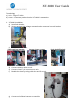
Test:
o) Connect power plug to power source
p) Put unit into install mode (on/off button) – see section below
q) Observe installer LED for green pass – see section below
r) If installer LED fail, refer to trouble shooting guide and fix issue
s) Take unit out of installer mode
t) Close the controller door.
u) Installation is complete.
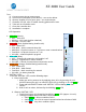
LED Operation
1. GPS LED (Green):
OFF – GPS OFF
Blinking – GPS Lock (position obtained)
ON solid – No GPS Lock
2. Asset LED (Red, disabled during install mode):
OFF – Asset OFF
Slow blink – Asset communications OK
Med blink – Physical connect on 7 pin but no asset communications
Fast blink – No physical connect on 7 pin
ON solid – software upload in progress
3. CELL LED (Blue):
OFF – Scanning for network or cell module is off
Blinking – Registered on cellular network
ON solid – Periods of network data transmission active
4. WLAN LED (Orange, disabled during install mode):
OFF - Mesh OFF
Slow blink – Mesh Bound
Fast blink - Mesh searching for network
ON solid - No battery detected
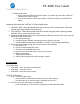
5. “INSTALL” LED
To use the “INSTALL” LED, use the following steps:
a. Enter Install mode
i. Make sure unit is powered on by applying asset AC or by pressing the unit
ON/OFF button (the unit is on when the GPS LED is flashing or on solid green).
ii. Press and hold ON/OFF button until “INSTALL” LED is blinking blue then
release
iii. Wait for unit to reboot, indicated by fast blinking green LED
b. Observe “INSTALL” LED
i. Testing in progress is indicated by fast blinking green LED (approx. 1-6 min)
ii. Testing is complete when solid LED is observed:
Solid GREEN: All test conditions PASS
Solid BLUE: No AC & No asset Communications but all others PASS
Solid RED: Any other conditions (fails)