
Inc. Portable Generator User Manual


MATLAB I/O 97
Xilinx Blocks
LogiCOREs, as well as signals and control circuits to drive the clock network.
Consequently, most System Generator blocks do not provide an explicit enable port.
There are two exceptions> the Register block and the Addressable Shift Register
block, which fundamentally require a CE port in order to target a high performance
hardware implementation.
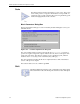
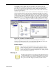
Simulink Enabled Subsystems can be used to enable blocks and subsystems. In order to
support System Generator’s bit and cycle true modeling in Simulink, it is required
that the enable port on an enabled subsystem be driven by the Enable Adapter block,
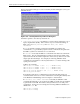
found in theXilinx blockset’sMATLAB I/Olibrary. An exampleof thisrequirement is
shown inthe figurebelow. This shows anaddress generationmodel for a MAC-based
FIR filter. The DownCount subsystem is stalled for a single sample period when the
CoefCount counter value is equal to the number of filter taps (in this case, 96 taps).
Figure 3-67: Example of enabled subsystem
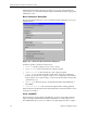
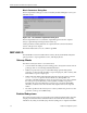
The following blocks cannot be placed in an enabled subsystem with System
Generator v2.1. The blocks are: CIC, Convolutional Encoder, FIR, FFT, Gateway In,
Gateway Out, RS Decoder, RS Encoder, and Viterbi Decoder.
Enable Adapter
When using an enabled subsystem that contains Xilinx blocks, the
enable port must be driven by a Xilinx Enable Adapter block. This
block is a required interface to any enabled subsystem that contains a
System Generatorblock. The Enable Adapterblock’s output port must
drive the subsystem’s enable port.
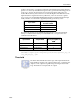
Gateway In
The XilinxGateway In block is theinput into the Xilinx FPGApart of
your Simulinkdesign. It convertsSimulink double precisioninput to
the System Generator fixed point type, and defines an input port for
the top level of the HDL design generated by System Generator.