
Inc. Interface Product Specification

PCI32 Interface v3.0
6 www.xilinx.com DS206 August 31, 2005
Product Specification v3.0.151
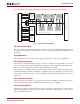
Target State Machine
This block controls the PCI interface target functions. The states implemented are a subset of those
defined in Appendix B of the PCI Local Bus Specification. The target control logic uses one-hot encoding
for maximum performance.
Interface Configuration
The PCI Interface can be easily configured to fit unique system requirements using the Xilinx CORE
Generator GUI or by changing the HDL configuration file. The following customization options,
among many others, are supported by the interface and are described in the PCI User Guide.
• Device and vendor ID
• Base Address Registers (number, size, and type)
Burst Transfer
The PCI bus derives its performance from its ability to support burst transfers. The performance of any
PCI application depends largely on the size of the burst transfer. Buffers to support PCI burst transfer
can efficiently be implemented using on-chip RAM resources.
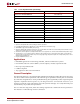
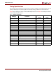
Supported PCI Commands
Table 3 illustrates the PCI bus commands supported by the PCI Interface.
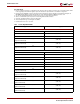
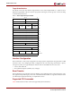
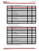
Table 2: PCI Configuration Space Header
31 16 15 0
Device ID Vendor ID
00h
Status Command
04h
Class Code Rev ID
08h
BIST Header
Type
Latency
Timer
Cache Line
Size
0Ch
Base Address Register 0 (BAR0)
10h
Base Address Register 1 (BAR1)
14h
Base Address Register 2 (BAR2)
18h
Base Address Register 3 (BAR3)
1Ch
Base Address Register 4 (BAR4)
20h
Base Address Register 5 (BAR5)
24h
Cardbus CIS Pointer
28h
Subsystem ID Subsystem Vendor ID
2Ch
Expansion ROM Base Address
30h
Reserved CapPtr
34h
Reserved
38h
Max Lat Min Gnt Int Pin Int Line
3Ch
Reserved
40h-FFh
Note: Shaded areas are not implemented and return zero.