
Inc. Network Card User Manual

1-Gigabit Ethernet MAC v8.5 User Guide www.xilinx.com 79
UG144 April 24, 2009
Using the Optional Management Interface
R
-- DISCONTINUED PRODUCT --
Receiver Configuration
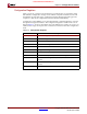
The register contents for the two receiver configuration words are shown in Table 8-3 and
Table 8-4.
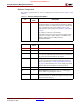
Table 8-3: Receiver Configuration Word 0
Bit
Default
Value
Description
31-0 All 0s Pause frame MAC Source Address[31:0]. This address is
used by the MAC to match against the destination address
of any incoming flow control frames. It is also used by the
flow control block as the source address (SA) for any
outbound flow control frames. See Chapter 6, “Using Flow
Control.”
The address is ordered so the first byte
transmitted/received is the lowest positioned byte in the
register; for example, a MAC address of AA-BB-CC-DD-
EE-FF would be stored in Address[47:0] as
0xFFEEDDCCBBAA.
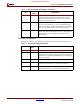
Table 8-4: Receiver Configuration Word 1
Bit
Default
Value
Description
15-0 All 0s Pause frame MAC Source Address[47:32]
23-16 n/a Reserved
24 0 Control Frame Length Check Disable When this bit is set
to ‘1,’ the core will not mark control frames as ‘bad’ if they
are greater than the minimum frame length.
25 0 Length/Type Error Check Disable When this bit is set to
‘1,’ the core will not perform the length/type field error
checks as described in “Length/Type Field Error Checks,”
on page 43. When this bit is set to ‘0,’ the length/type field
checks will be performed; this is normal operation.
26 n/a Reserved
27 0 VLAN Enable When this bit is set to ‘1,’ VLAN tagged
frames will be accepted by the receiver.
28 1 Receiver Enable. If set to ‘1,’ the receiver block will be
operational. If set to ‘0,’ the block will ignore activity on the
physical interface RX port.