LogiCORE™ PCI v3.0 Getting Started Guide UG157 August 31, 2005 v3.0.
R Xilinx is disclosing this Specification to you solely for use in the development of designs to operate on Xilinx FPGAs. Except as stated herein, none of the Specification may be copied, reproduced, distributed, republished, downloaded, displayed, posted, or transmitted in any form or by any means including, but not limited to, electronic, mechanical, photocopying, recording, or otherwise, without the prior written consent of Xilinx.
Version 06/24/02 3.0 Revision Initial Xilinx release of corporate-wide common template set, used for User Guides, Tutorials, Release Notes, Manuals, and other lengthy, multiple-chapter documents created by both CMP and ITP. See related documents for further information. Descriptions for revisions prior to v3.0 have been abbreviated. For a full summary of revision changes prior to v3.0, refer to v2.2.1 template set. 10/30/02 3.1 Updated spelling of RocketIO and SelectIO trademarks in ug000_title.
PCI v3.0.151 Getting Started Guide UG157 August 31, 2005 www.xilinx.
Table of Contents Preface: About This Guide Guide Contents . . . . . . . . . . . . . . . . . . . . . . . . . . . . . . . . . . . . . . . . . . . . . . . . . . . . . . . 7 Additional Resources . . . . . . . . . . . . . . . . . . . . . . . . . . . . . . . . . . . . . . . . . . . . . . . . . 8 Conventions . . . . . . . . . . . . . . . . . . . . . . . . . . . . . . . . . . . . . . . . . . . . . . . . . . . . . . . . . . 8 Typographical . . . . . . . . . . . . . . . . . . . . . . . . . . . . . . . . . . . . . .
Chapter 5: Synthesizing a Design Synplicity Synplify . . . . . . . . . . . . . . . . . . . . . . . . . . . . . . . . . . . . . . . . . . . . . . . . . . . 43 Verilog . . . . . . . . . . . . . . . . . . . . . . . . . . . . . . . . . . . . . . . . . . . . . . . . . . . . . . . . . . . . . . . . . . 43 VHDL . . . . . . . . . . . . . . . . . . . . . . . . . . . . . . . . . . . . . . . . . . . . . . . . . . . . . . . . . . . . . . . . . . . 48 Exemplar LeonardoSpectrum . . . . . . . . . . . . . . . . . . . . .
R Preface About This Guide The PCI Getting Started Guide provides information about the LogiCORE™ Peripheral Component Interconnect (PCI) interface, which provides a fully verified, pre-implemented PCI bus interface available in both 32-bit and 64-bit versions. This guide discusses the supported design flows for 32-bit and 64-bit PCI interfaces based on the Virtex™ and Spartan™ architectures, and provides an example design in both Verilog-HDL and VHDL.
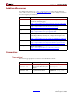
R Preface: About This Guide Additional Resources For additional information, go to http://support.xilinx.com. The following table lists some of the resources you can access from this website. You can also directly access these resources using the provided URLs. Resource Tutorials Description/URL Tutorials covering Xilinx design flows, from design entry to verification and debugging http://support.xilinx.com/support/techsup/tutorials/index.
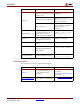
R Conventions Convention Meaning or Use Example Variables in a syntax statement for which you must supply values ngdbuild design_name References to other manuals See the Development System Reference Guide for more information. Emphasis in text If a wire is drawn so that it overlaps the pin of a symbol, the two nets are not connected. An optional entry or parameter. However, in bus specifications, such as bus[7:0], they are required.
R 10 Preface: About This Guide www.xilinx.com PCI v3.0.
R Chapter 1 Getting Started The PCI interface provides a fully verified, pre-implemented PCI bus interface available in both 32-bit and 64-bit versions with support for operation at 33 MHz and 66 MHz. This guide defines the supported design flows for both the 32-bit and 64-bit interfaces targeting devices based on the Virtex and Spartan architectures.
R Chapter 1: Getting Started Technical Support For technical support, visit www.xilinx.com/support. Questions are routed to a team of engineers with expertise using the PCI interface. Xilinx provides technical support for use of this product as described in the PCI User Guide and the PCI Getting Started Guide. Xilinx cannot guarantee timing, functionality, or support of this product for designs that do not follow these guidelines.
R Chapter 2 Installing and Licensing the Core This chapter provides instructions for installing and obtaining a license for the PCI interface core, which you must do before using it in your designs. The PCI core is provided under the terms of the Xilinx LogiCORE Site License Agreement or the Xilinx LogiCORE Project License Agreement, which conform to the terms of the SignOnce IP License/Project standard defined by the Common License Consortium.
R Chapter 2: Installing and Licensing the Core CORE Generator IP Updates Installer 1. From the CORE Generator main GUI, choose Tools > Updates Installer to start the Updates Installer. 2. If prompted for a proxy host, contact your administrator to determine the proxy host address and port number you need to get through your firewall. 3. Select 7.1i_IP_Update3 from the list of updates in the Available Packages panel. 4. Click Add To Install Queue to add the update ZIP file to the install queue. 5.
R Installing the Core the location of the Xilinx installation. Note that you may need system administrator privileges to install the update. 6.
R Chapter 2: Installing and Licensing the Core Licensing Options Evaluation The method for obtaining an evaluation license is determined by the version of the PCI core you choose. • For the PCI32/33 Virtex™ and Spartan™ core, register on the Xilinx IP Evaluation page at www.xilinx.com/ipcenter/ipevaluation. From this location, access is granted and you can generate your own license. • For the PCI 64/66 core, please contact your locate FAE to request a Full System Hardware Evaluation license key.
R Installing Your License File Installing Your License File After selecting a license option, an email will be sent to you that includes instructions for installing your license file. In addition, information about advanced licensing options and technical support is provided. PCI v3.0.151 Getting Started Guide UG157 August 31, 2005 www.xilinx.
R 18 Chapter 2: Installing and Licensing the Core www.xilinx.com PCI v3.0.
R Chapter 3 Family Specific Considerations This chapter provides important design information specific to the PCI interface targeting Virtex and Spartan devices. Design Support Table 3-1 provides a list of supported device and interface combinations. Each entry in the table consists of a device, a bus interface type, and two or three specific implementation files.
R Chapter 3: Family Specific Considerations Table 3-1: Device and Interface Selection Table (Continued) Supported Device 2S200-FG456-6C Bus Type 33 MHz Wrapper File pcim_lc_33_3_s 3.3V Constraints File/ Guide File 2s200fg456_64_33.ucf no guide file 64-bit 2S200-FG456-6C 66 MHz pcim_lc_66_3_d 3.3V 2s200fg456_64_66.ucf 2s200fg456_64_66.ncd 64-bit 2S100E-FG456-6C 33 MHz pcim_lc_33_3_s 3.3V 2s100efg456_64_33.ucf no guide file 64-bit 2S150E-FG456-6C 33 MHz pcim_lc_33_3_s 3.
R Design Support Table 3-1: Device and Interface Selection Table (Continued) Supported Device V300E-BG432-6C Bus Type Wrapper File 66 MHz pcim_lc_66_3_d 3.3V Constraints File/ Guide File v300ebg432_64_66.ucf v300ebg432_64_66.ncd 64-bit V300E-BG432-6C 33 MHz pcim_lc_33_3_s 3.3V v300ebg432_64_33.ucf no guide file 64-bit V1000-FG680-6C 66 MHz pcim_lc_66_3_d 3.3V v1000fg680_64_66.ucf v1000fg680_64_66.ncd 64-bit V1000-FG680-5C 33 MHz pcim_lc_33_5_s 5.0V v1000fg680_64_33.
R Chapter 3: Family Specific Considerations Table 3-1: Device and Interface Selection Table (Continued) Supported Device 2VP20-FF1152-6C/I Bus Type 66 MHz Wrapper File pcim_lc_66_3_s 3.3V Constraints File/ Guide File 2vp20ff1152_64_66.ucf 2vp20ff1152_64_66.ncd 64-bit 2VP20-FF1152-5C/I 33 MHz pcim_lc_33_3_s 3.3V 2vp20ff1152_64_33.ucf no guide file 64-bit 2VP30-FF1152-6C/I 66 MHz pcim_lc_66_3_s 3.3V 2vp30ff1152_64_66.ucf 2vp30ff1152_64_66.
R Design Support Table 3-1: Device and Interface Selection Table (Continued) Supported Device 4VSX35-FF668-10C/I global clock Bus Type Wrapper File Constraints File/ Guide File 33 MHz pcim_lc_33_3_g 4vsx35ff668_64_33g.ucf 3.3V no guide file 64-bit 4VFX20-FF672-10C/I global clock 33 MHz pcim_lc_33_3_g 3.3V 4vfx20ff672_64_33g.ucf no guide file 64-bit 4VLX25-FF668-10C/I regional clock 33 MHz pcim_lc_33_3_r 3.3V 4vlx25ff668_64_33r.
R Chapter 3: Family Specific Considerations Table 3-1: Device and Interface Selection Table (Continued) Supported Device 2S50-PQ208-5C Bus Type 33 MHz Wrapper File pcim_lc_33_3_s 3.3V Constraints File/ Guide File 2s050pq208_32_33.ucf no guide file 32-bit 2S100-PQ208-5C 33 MHz pcim_lc_33_5_s 5.0V 2s100pq208_32_33.ucf no guide file 32-bit 2S100-PQ208-5C 33 MHz pcim_lc_33_3_s 3.3V 2s100pq208_32_33.ucf no guide file 32-bit 2S150-PQ208-5C 33 MHz pcim_lc_33_5_s 5.0V 2s150pq208_32_33.
R Design Support Table 3-1: Device and Interface Selection Table (Continued) Supported Device 2S300E-PQ208-6C Bus Type 33 MHz Wrapper File pcim_lc_33_3_s 3.3V Constraints File/ Guide File 2s300epq208_32_33.ucf no guide file 32-bit V100E-BG352-6C 33 MHz pcim_lc_33_3_s 3.3V v100ebg352_32_33.ucf no guide file 32-bit V300-BG432-5C 33 MHz pcim_lc_33_5_s 5.0V v300bg432_32_33.ucf no guide file 32-bit V300-BG432-5C 33 MHz pcim_lc_33_3_s 3.3V v300bg432_32_33.
R Chapter 3: Family Specific Considerations Table 3-1: Device and Interface Selection Table (Continued) Supported Device 3S1200E-FG400-4C/I Bus Type 33 MHz Wrapper File pcim_lc_33_3_s 3.3V Constraints File/ Guide File 3s1200efg400_32_33.ucf no guide file 32-bit V200-FG256-6C 66 MHz pcim_lc_66_3_d 3.3V v200fg256_32_66.ucf v200fg256_32_66.ncd 32-bit V200E-FG256-6C 66 MHz pcim_lc_66_3_d 3.3V v200efg256_32_66.ucf v200efg256_32_66.ncd 32-bit V400E-FG676-6C 66 MHz pcim_lc_66_3_d 3.
R Design Support Table 3-1: Device and Interface Selection Table (Continued) Supported Device 4VSX35-FF668-11C/I regional clock Bus Type 66 MHz Wrapper File pcim_lc_66_3r 3.3V Constraints File/ Guide File 4vsx35ff668_32_33r.ucf no guide file 32-bit 4VFX20-FF672-11C/I regional clock 66 MHz 3.3V pcim_lc_66_3r 4vfx20ff672_32_33r.ucf no guide file 32-bit See the product release notes included with the core for a complete directory structure and file list. PCI v3.0.
R Chapter 3: Family Specific Considerations Wrapper Files Wrapper files contain an instance of the PCI interface and the instances of all I/O elements used by the PCI interface. Each wrapper file is specific to a particular PCI bus signaling environment. The wrapper files, located in the /hdl/src/wrap directory, are actually variations of the pcim_lc.hdl file located in the /hdl/src/xpci directory.
R Device Initialization Table 3-2: Guide File Information Guide File Components Connections 2vp40ff1152_64_66.ncd 153 246 2vp50ff1152_64_66.ncd 153 246 v200fg256_32_66.ncd 90 86 v200efg256_32_66.ncd 90 86 v400fg676_32_66.ncd 90 86 Device Initialization Immediately after FPGA configuration, both the PCI interface and the user application are initialized by the startup mechanism present in all Virtex and Spartan devices.
R Chapter 3: Family Specific Considerations Although this technique is not technically compliant with the PCI specification due to the extra loading on REQ64# and RST#, the use of a large series resistor helps minimize this effect. The inverter may be pushed into the FPGA. An alternate method is to push the entire circuit into the FPGA and use the REQ64Q_N and RST signals provided to the user application. This method requires that the FPGA be fully configured by the rising edge of RST#.
R Input Delay Buffers IOBs of the FPGA device.
R Chapter 3: Family Specific Considerations 1. The jitter of the source clock, to determine if it is appropriate for use as an input to a DCM. 2. The DCM configuration, to generate a 200 MHz clock on any appropriate DCM output (CLKFX, CLKDV, and so forth). 3. The jitter of the derived 200 MHz reference clock, to determine if it is appropriate for use as an input to an IDELAYCTRL. For more information about the relevant timing parameters, see the Virtex-4 Datasheet and User Guide.
R Regional Clock Usage BUFR Figure 3-2: Regional Clocking Illustration For designs using regional clocking, the PCI interface and those portions of the user application clocked from the PCI bus clock must completely fit inside the three clock regions accessible to the regional clock signal. This restriction limits the number of FPGA resources that may be synchronous with the PCI bus clock. Access to additional logic is available by crossing to another clock domain.
R Chapter 3: Family Specific Considerations Table 3-4: Virtex-4 Device and Package 64-bit Interfaces Package FF668 FF1148 FF1513 FF672 FF1152 FF1517 FF1760 Device 64-bit Interfaces LX15 2 LX25 4 LX40 2 LX60 2 FX12 2 SX25 2 SX35 4 LX40 4 LX60 4 LX80 6 LX100 6 LX160 6 SX55 4 LX100 8 LX160 8 LX200 8 FX20 2 FX40 none FX60 none FX40 4 FX60 4 FX100 4 FX100 6 FX140 6 FX140 8 Bus Clock Usage The bus clock output provided by the interface is derived from
R Electrical Compliance maximum allowed frequency, and the frequency may change on a cycle-by-cycle basis. Under certain conditions, the PCI core may also apply phase shifts to this clock. For these reasons, the user application should not use this clock as an input to a DLL or PLL, nor should the user application use this clock in the design of interval timers (for example, DRAM refresh counters).
R Chapter 3: Family Specific Considerations 2.70 2.65 VCCINT (V) 2.60 2.55 3.3V PCI COMPLIANT REGION 2.50 2.45 2.40 2.35 2.30 3.00 3.05 3.10 3.15 3.20 3.25 3.30 3.35 3.40 3.45 3.50 3.55 3.60 System Supply (V) Figure 3-3: Relationship For 3.3V Input Buffer Compliance Figure 3-3 shows the small range of supply voltage values where VIL or VIH are technically non-compliant.
R Generating Bitstreams Figure 3-4 shows one possible low-cost solution to generate the required 3.0 volt output driver supply. Xilinx recommends the use of the circuit shown in Figure 3-4, although other approaches using other regulators are possible. SUPPLY 8 IN OUT 1 5 SHDN# ADJ 2 7 GND BYP 4 6 GND GND 3 VCCO 38.3, 1% LT1763CS8 +3.0V SUPPLY 1.0 uF 3.3 uF 26.
R Chapter 3: Family Specific Considerations This option is used to introduce additional delay on a global clock net. It is important to note that this additional delay is observable on the CLK output of the PCI interface, which is supplied to the user application. Timing constraints for the user application must be generated with this in mind. 38 www.xilinx.com PCI v3.0.
R Chapter 4 Functional Simulation This chapter describes how to simulate the ping64 example design with global clocks using the supported functional simulation tools. For the PCI 32 interface, substitute ping32 for ping64. If you are using a design with reference clocks, substitute with pcim_top_r and ping_tb with ping_tb_r. Supported functional simulation tools include • Cadence NC-Verilog v.5.0 • Model Technology ModelSim v5.
R Chapter 4: Functional Simulation Most of the files listed are related to the example design and its testbench. For other testbenches, the following subset must be used for proper simulation of the PCI interface: ../source/glbl.v ../../src/xpci/pci_lc_i.v ../../src/xpci/pcim_lc.v +libext+.vmd+.v -y /verilog/src/unisims -y /verilog/src/simprims This list does not include any configuration file, user application, top level wrapper, or testbench.
R Model Technology ModelSim 3. Modify the library search path by changing to match the Xilinx installation directory and then save the file. Most of the files listed are related to the example design and its testbench. For other testbenches, the following subset must be used for proper simulation of the PCI interface: ../source/glbl.v ../../src/xpci/pci_lc_i.v ../../src/xpci/pcim_lc.v +libext+.vmd+.
R Chapter 4: Functional Simulation /vhdl/example/func_sim 4. Create the simprim and unisim libraries. This step only needs to be done once, the first time you perform a simulation: vlib simprim vcom -93 -work simprim /vhdl/src/simprims/simprim_Vpackage_mti.vhd vcom -93 -work simprim /vhdl/src/simprims/simprim_Vcomponents_mti.vhd vcom -93 -work simprim /vhdl/src/simprims/simprim_VITAL_mti.
R Chapter 5 Synthesizing a Design This chapter describes how to synthesize the ping64 example design with global clocks using the supported synthesis tools. For the PCI 32 interface, substitute ping32 for ping64. If you are using a design with reference clocks, substitute pcim_top with pcim_top_r and ping_tb with ping_tb_r. Supported synthesis tools include • Synplicity Synplify v7.
R Chapter 5: Synthesizing a Design Figure 5-6: 4. Main Project Window To add source files to the new project, click Add. The first file (used by any design that instantiates Xilinx primitives) is located in: /lib/xilinx 5. Navigate to the virtex.v file; then click Add to move this source file into the Files To Add list. Figure 5-7: 44 Select Files to Add (Library) www.xilinx.com PCI v3.0.
R Synplicity Synplify The next files are located in: /verilog/src/xpci 6. Navigate to the xpci directory, select the simulation model and the wrapper files (pci_lc_i.v and pcim_lc.v), and click Add to move these files into the Files To Add list. (Ctrl-click to select multiple files.) Figure 5-8: Files to Add (LogiCORE Files) The final set of design files (the user application) is located in: /verilog/example/source 7.
R Chapter 5: Synthesizing a Design 8. After adding the three final files (for a total of six source files), click OK to return to the main project window. 9. In the Source Files list, view the list of newly added source files by double-clicking the flowtest/verilog folder (if it is not already open). Reorder the source files in the folder by dragging them to list them in the hierarchical order displayed in Figure 5-10. Figure 5-10: Main Project Window with Source Files 10.
R Synplicity Synplify Figure 5-11: Options for Implementation: Device 13. On the Device tab, set the Technology, Part, Speed, and Package options to reflect the targeted device (a V300BG432-6 in this example). Be sure that Disable I/O Insertion is deselected. 14. On the Options/Constraints tab, deselect Symbolic FSM Compiler (but leave Resource Sharing selected) and set the Frequency to 66 MHz. 15. On the Implementation Results tab, deselect Write Vendor Constraint File. 16.
R Chapter 5: Synthesizing a Design VHDL 1. Start Synplify and choose File > New, or use the new file icon on the toolbar. The New dialog box appears. Figure 5-12: 2. Create a New Project Under File Type, select Project File and enter the project name (flowtest in this example) and synthesis directory: /vhdl/example/synthesis 3. Click OK to exit the dialog box and return to the project window. Figure 5-13: 4. Main Project Window To add source files to the new project, click Add.
R Synplicity Synplify 5. Select the virtex.vhd file; then click Add to move this source file into the Files To Add list. Figure 5-14: Select Files to Add (Library) The next files are located in: /vhdl/src/xpci 6. Navigate to the xpci directory, select the simulation model and the wrapper files (pci_lc_i.vhd and pcim_lc.vhd), and click Add to move these files into the Files To Add list. (Ctrl-click to select multiple files.) Figure 5-15: PCI v3.0.
R Chapter 5: Synthesizing a Design The final set of design files (the user application) is located in: /vhdl/example/source 7. Navigate to the source directory, select the cfg_ping.vhd, pcim_top.vhd, and ping.vhd, then click Add. 8. After adding the three final files (for a total of six source files), click OK to return to the main project window. 9.
R Exemplar LeonardoSpectrum 12. From the main project window, click Change Target to display the Options for Implementation dialog box, as shown in Figure 5-17. Figure 5-17: Options for Implementation 13. On the Device tab, set the Technology, Part, Speed, and Package options to reflect the targeted device (a V300BG432-6 in this example). Be sure that Disable I/O Insertion is deselected. 14.
R Chapter 5: Synthesizing a Design The end result of the synthesis step is an EDIF file that is fed into the Xilinx implementation tools during the implementation step. In practice, the provided script file must be modified to accommodate other designs. To provide insight into the synthesis script, the major steps are presented below: 1. Various synthesis options are set through the use of environment variables. These must be present in the script, and should not be modified.
R Chapter 6 Implementing a Design This chapter describes how to implement the ping64 example design with global clocks using the supported FPGA implementation tools (included with the ISE Foundation v7.1 Development System). For the PCI 32 interface, substitute ping32 for ping64. If you are using a design with reference clocks, substitute pcim_top with pcim_top_r and ping_tb with ping_tb_r.
R Chapter 6: Implementing a Design • The par command, as provided in the script, uses a guide file in exact guide mode. Note that some designs do not require the use of guide files. To target a different device or to use a different version of the PCI interface, see Chapter 3, “Family Specific Considerations.” If a guide file is required, ensure that the correct guide file is used by editing the script and changing the file name.
R Chapter 7 Timing Simulation This chapter describes how to perform timing simulation using the ping64 example design with global clocks using the supported timing simulation tools. For the PCI 32 interface, substitute ping32 for ping64. If you are using a design with reference clocks, substitute pcim_top with pcim_top_r and ping_tb with ping_tb_r. Supported timing simulation tools include • Cadence NC-Verilog v.5.0 • Model Technology ModelSim v5.
R Chapter 7: Timing Simulation NC-Verilog processes the simulation files and exits. The testbench prints status messages to the console. After the simulation completes, view the ncverilog.log file to check for errors. The Simvision browser may be used to view the simulation results. Simvision is started with the following command: simvision Model Technology ModelSim Before attempting timing simulation, ensure that the ModelSim environment is properly configured for use.
R Model Technology ModelSim cp ../xilinx/pcim_top_routed.sdf . 2. View the ping.files file. This file lists the individual source files required, and is shown below: ./pcim_top_routed.vhd ../source/busrecord.vhd ../source/dumb_arbiter.vhd ../source/dumb_targ32.vhd ../source/dumb_targ64.vhd ../source/stimulus.vhd ../source/ping_tb.vhd 3. Invoke ModelSim, and ensure that the current directory is set to: /vhdl/example/post_sim 4. Create the simprim library.
R 58 Chapter 7: Timing Simulation www.xilinx.com PCI v3.0.