LogiCORE™ IP CAN v3.
Xilinx is providing this product documentation, hereinafter “Information,” to you “AS IS” with no warranty of any kind, express or implied. Xilinx makes no representation that the Information, or any particular implementation thereof, is free from any claims of infringement. You are responsible for obtaining any rights you may require for any implementation based on the Information. All specifications are subject to change without notice.
Table of Contents Schedule of Figures . . . . . . . . . . . . . . . . . . . . . . . . . . . . . . . . . . . . . . . . . . . . . . . . . . . . . . . . . . 5 Preface: About This Guide Guide Contents . . . . . . . . . . . . . . . . . . . . . . . . . . . . . . . . . . . . . . . . . . . . . . . . . . . . . . . . . . . . . . 7 Conventions . . . . . . . . . . . . . . . . . . . . . . . . . . . . . . . . . . . . . . . . . . . . . . . . . . . . . . . . . . . . . . . . . 7 Typographical . . . . . . . . . . . . . . .
Chapter 4: Detailed Example Design Directory and File Contents . . . . . . . . . . . . . . . . . . . . . . . . . . . . . . . . . . . . . . . . . . . . . . . . . 18 . . . . . . . . . . . . . . . . . . . . . . . . . . . . . . . . . . . . . . . . . . . . . . . . . . . . . . . / . . . . . . . . . . . . . . . . . . . . . . . . . . . . . . . . . . . . example design . . . . . . . . . . . . . . . . . . . . . . . . . . . . . . . . . . . . . . .
Schedule of Figures Chapter 1: Introduction Chapter 2: Licensing the Core Chapter 3: Quick Start Example Design Figure 3-1: Example Design . . . . . . . . . . . . . . . . . . . . . . . . . . . . . . . . . . . . . . . . . . . . . . . . . . . . 13 Figure 3-2: CAN Main Screen . . . . . . . . . . . . . . . . . . . . . . . . . . . . . . . . . . . . . . . . . . . . . . . . . . 14 Chapter 4: Detailed Example Design Figure 4-1: Example Design Configuration. . . . . . . . . . . . . . . . . . . . . . . . . . . . . .
www.xilinx.
Preface About This Guide The CAN v3.2 Getting Started Guide provides information about generating the LogiCORE™ IP CAN core, customizing and simulating the core with the provided example design, and running the design files through implementation using the Xilinx tools. Guide Contents The following chapters are included in this guide: • Preface, “About This Guide” introduces the organization and purpose of this Getting Started Guide and the conventions used in this document.
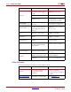
Preface: About This Guide Convention Meaning or Use Example Variables in a syntax statement for which you must supply values ngdbuild design_name References to other manuals See the User Guide for details. Emphasis in text If a wire is drawn so that it overlaps the pin of a symbol, the two nets are not connected. Dark Shading Items that are not supported or reserved This feature is not supported Square brackets An optional entry or parameter.
Chapter 1 Introduction The LogiCORE™ IP CAN v3.2 core is a compact, full-featured targeted design platform that conforms to ISO 11898-1, CAN2.0A and CAN2.0B standards. Bit rates of up to 1 Mbps are supported. The core size can be optimized using parameterized configurations for acceptance filtering and FIFO depth. The example design in this guide is provided in both Verilog and VHDL.
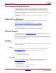
Chapter 1: Introduction Recommended Design Experience Although the CAN core is a fully-verified targeted design platform, the challenge associated with implementing a complete CAN design varies, depending on the application requirements. For best results, previous experience with building highperformance FPGA designs using Xilinx implementation software and a user constraints file (UCF) is recommended. Contact your local Xilinx representative for assistance in evaluating your specific requirements.
Chapter 2 Licensing the Core This chapter provides instructions for obtaining a license for the CAN core, which you must do before using the core in your designs. The CAN core is provided under the terms of the Xilinx LogiCORE Site License Agreement, which conforms to the terms of the SignOnce IP License standard defined by the Common License Consortium. Purchase of the core entitles you to technical support and access to updates for one year.
Chapter 2: Licensing the Core Full The Full license key is available when you purchase the core and provides full access to all core functionality both in simulation and in hardware, including: • Gate-level functional simulation support • Back annotated gate-level simulation support • Functional simulation support • Full-implementation support including place and route and bitstream generation • Full functionality in the programmed device with no time-outs Obtaining Your License Key This section
Chapter 3 Quick Start Example Design This chapter provides instructions to generate a CAN core quickly, run the design through implementation with the Xilinx tools, and simulate the example design using the provided demonstration test bench. See the example design in Chapter 4, “Detailed Example Design.” Overview Figure 3-1 illustrates the CAN example design.
Chapter 3: Quick Start Example Design Generating the Core This section describes how to generate a CAN core with default values using the Xilinx CORE Generator™ tool. To generate the core: 1. Start the CORE Generator tool. For help starting and using the CORE Generator tool, see the Xilinx CORE Generator Guide, available from the ISE documentation web page. 2. Choose File > New Project. 3. Type a directory name. This example uses the directory name design. 4.
Implementing the Example Design 7. In the Component Name field, enter a name for the core instance. This example uses the name quickstart. 8. After selecting the parameters from the GUI screens, click Finish. The core and its supporting files, including the example design, are generated in the project directory. For detailed information about the example design files and directories see Chapter 4, “Detailed Example Design.
Chapter 3: Quick Start Example Design Functional Simulation This section provides instructions for running a functional simulation of the CAN core using either VHDL or Verilog. Functional simulation models are provided when the core is generated. Implementing the core before simulating the functional models is not required. To run a VHDL or Verilog functional simulation of the example design: 1. Set the current directory to: /simulation/functional/ 2. Launch the simulation script.
Chapter 4 Detailed Example Design This chapter provides detailed information about the example design, including a description of files and the directory structure generated by the Xilinx CORE Generator™ software, the purpose and contents of the provided scripts, the contents of the example HDL wrappers, and the operation of the demonstration test bench.
Chapter 4: Detailed Example Design Directory and File Contents The CAN v3.2 core directories and their associated files are defined in the following sections. The contains all the CORE Generator software project files. Table 4-1: Project Directory Name Description .ngc Top-level netlist .v[hd] Verilog or VHDL simulation model .
Directory and File Contents example design The example design directory contains the example design files provided with the core. Table 4-3: Example Design Directory Name Description //example_design _top.ucf Provides example constraints necessary for processing the CAN core using the Xilinx implementation tools. _top.v[hd] The VHDL or Verilog top-level file for the example design; it instantiates the CAN core.
Chapter 4: Detailed Example Design /implement The implement directory contains the core implementation script files. Generated for FullSystem Hardware Evaluation and Full license types. Table 4-5: Implement Directory Name Description //implement implement.{bat|sh} A Windows (.bat) or Linux script that processes the example design. xst.prj The XST project file for the example design that lists all of the source files to be synthesized.
Directory and File Contents /simulation/functional The functional directory contains functional simulation scripts provided with the core. Table 4-8: Functional Directory Name Description //simulation/functional simulate_mti.do A macro file for ModelSim that compiles the HDL sources and runs the simulation. simulate_ncsim.sh A macro file for Cadence IES that compiles the HDL sources and runs the simulation in a Linux environment. simulate_ncsim.
Chapter 4: Detailed Example Design simulation/timing The timing simulation directory is generated only for Full-System Hardware Evaluation and Full-license types. Table 4-9: Timing Directory Name Description //simulation/timing simulate_mti.do A macro file for ModelSim that compiles the post-par timing netlist, demonstration test bench files, and runs the simulation. simulate_ncsim.
Implementation Scripts Implementation Scripts Note: Present only with a Full license. The implementation script is either a shell script(.sh) or batch file (.bat) that processes the example design through the Xilinx tool flow. It is located at: Linux //implement/implement.sh Windows //implement/implement.
Chapter 4: Detailed Example Design Timing Simulation Note: Present only with a Full license. The test scripts are a ModelSim or a Cadence IES macro that automates the simulation of the test bench.
Demonstration Test Bench Demonstration Test Bench Figure 4-2 illustrates the demonstration test bench. X-Ref Target - Figure 4-2 Demonstration Test Bench CAN Example Design Clock Generator Stimulus Generator User Interface IOBs CAN Core CAN Phy IOBs Checker Figure 4-2: Demonstration Test Bench Test Bench Functionality The demonstration test bench is a straightforward VHDL or Verilog file to exercise the example design and the core itself.
Chapter 4: Detailed Example Design • Five messages are written in sequence: 1. The first message is written to the TXHPB and is a standard data frame. 2. The second message is written to the TX FIFO and is a standard data frame. 3. The third message is written to the TX FIFO and is a standard remote frame. 4. The fourth message is written to the TX FIFO and is an extended data frame. 5. The fifth message is written to the TX FIFO and is an extended remote frame.
Demonstration Test Bench • After the fourth message is transmitted and received, the Interrupt Enable Register is written to enable interrupts for TXOK, RXOK and TXBFLL. This register is read from and the value read is compared with the value written. • The fifth message does not pass acceptance filtering. Only the TXOK bit in the ISR is set when the ISR is asserted.
Chapter 4: Detailed Example Design 28 www.xilinx.