XEROX WIDE FORMAT COPY SYSTEM 8825, 8830,8850, 510 Series, 721P & X2 TECH XEROX WIDE FORMAT COPY SYSTEM User Guide AccXES Firmware Version 10.
Contents Getting to know the WIDE FORMAT COPY SYSTEM 1 Getting to know the WIDE FORMAT COPY SYSTEM ............................................................. 1 Scanner standard components............................................................................................. 3 Scanner compact components............................................................................................. 7 Scanner Control Panel.................................................................................
Type Photo............................................................................................................... 42 Type, Color .............................................................................................................. 43 Background Suppression ................................................................................................... 45 Copy ..................................................................................................................................
Main Menu 88 Main Menu .......................................................................................................................... 88 Configuration menu............................................................................................................ 89 LOCALIZATION........................................................................................................ 90 CONTROL PANEL .................................................................................................
Appendix 5........................................................................................................................ 151 Appendix 6........................................................................................................................ 151 Appendix 7........................................................................................................................
Getting to know the WIDE FORMAT COPY SYSTEM Getting to know the WIDE FORMAT COPY SYSTEM This manual contains operating instructions for the user and the system administrator for the XEROX WIDE FORMAT COPY SYSTEM 8825/8830/8850/510 Series and 721P with version 10.0 AccXES firmware loaded into the Controller. Your XEROX WIDE FORMAT COPY SYSTEM is an integrated solution for electronically scanning and then printing images for engineering or architectural use.
Table 1.
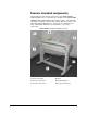
Scanner standard components The illustrations below show the components of the WIDE FORMAT SCAN SYSTEM. These components are standard on the XEROX WIDE FORMAT COPY SYSTEM 8825, 8830, 8850,510 Series. And X2 TECH. The Stand is standard or optional on the 8850. With the exception of the Stand and Standard Organizer, the components are standard on the 721P. Following the illustrations are descriptions of each of the components.
WIDE FORMAT SCAN SYSTEM Front View B A C F D A: Document Handler D: Stand B: Scanner Control Panel E: Productivity Document Feed-in Tray C: Thick Document Lever A. Document Handler Raise the Document Handler for routine maintenance functions and to access the optical paper sensors for diagnostic routines. B. Scanner Control Panel The control panel allows the selection of options and features and contains a graphical display for the communication of information and instructions.
E. Standard Organizer The Organizer is located on the front of the Scanner. It is useful for holding multiple documents that are to be scanned. It has two extensions at its end that can be pulled out to accommodate longer documents (up to size E or A0). F Document Feed Tray Insert documents to be scanned face down and centered into the Document Feed Tray. F. Productivity Document Feed Tray Provides built-in Document Width Sensors that eliminate the need to prescan document to do width measurement.
A. Standard Stacker The Stacker is located at the rear of the Scanner. When the AUTORETURN feature is set to REAR, documents exit the Scanner onto the Stacker. The Stacker can be adjusted to any one of four positions by raising or lowering it. The height of the Stacker should be adjusted to accommodate the document being scanned. It has two extensions at its end that can be pulled out to accommodate longer documents (up to size E or A0).
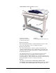
Scanner compact components The illustrations show the optional compact Stacker and organizer that are available for the WIDE FORMAT SCAN SYSTEM. The compact components allow the XEROX WIDE FORMAT COPY SYSTEM to be installed in sites where space requirements are at a premium.
Rear View A: Compact Stacker 8 •Getting to know the WIDE FORMAT COPY SYSTEM XEROX WIDE FORMAT COPY SYSTEM
Scanner Control Panel The Scanner Control Panel is divided into three sections: • The options keys section, which contains the - Media Selection, Image Quality, and Reduce/Enlarge options selections • The graphical display and the navigation keys section. • The right-hand section, which contains the numeric keypad, the special features keys, and the scan control keys. If the BEEP function is enabled (factory default), a beep sound will be heard when a key is pressed.
Control Panel Options Area Media Selection The Media Selection area of the Scanner Control Panel allows you to select the media Source, Type, and Output Format. The illustration below depicts the Media Selection portion of the control panel.
Source The Source option allows you to select the source of the media on which the image will be printed. To select the media source, press the key beneath the Source settings until the desired source indicator lamp illuminates. The Source settings are: • Sheet - This setting tells the Printer to print from a manually inserted sheet of media. • R4 - This setting is applicable to the WIDE FORMAT COPY SYSTEM 721P only.
Output Format The Output Format option allows you to select the size to which the roll feed media will be cut. It has three modes - Manual, Preset, and Synchro. Manual Manual allows you to enter the desired length and width manually. To select the Manual mode: 1. Press the key beneath Output Format until the Manual indicator lamp illuminates. The CUSTOM OUTPUT FORMAT screen is displayed. NOTE: If the indicator lamp is already lit, press the key once to display the screen.
PRESET OUTPUT FORMAT SELECT: 2. 8.5 X 11 ANSI A Press the Previous or Next key to select an item from the list. NOTE: Formats can be added or removed from this list. Refer to "Custom Media Formats" in the "Main Menu" section for more information. 3. Press the Enter key to confirm the choice and return to the READY screen.
The SCAN SYSTEM firmware must be at version 3.0.9 or greater to support Normal, Line, Photo, or Color Type. If the SCAN SYSTEM is not at the required version an error message. Depending on what Mode is selected (COPY or SCAN) the message will be displayed as show below. INVALID MODE UPGRADE SCANNER FIRMWARE AUTO 100.
Original, Type The Type option allows you to specify the type classification of your document. To select the document type, press the key beneath the Type settings until the desired Type indicator lamp illuminates. Normal Normal — (factory default) Select Normal for most copying needs. This setting will provide good image quality for copying most types of drawings. Shaded areas will be preserved. In the SCAN mode, the following screen is displayed when the Normal key is pressed.
NOTE: The Background Suppression option cannot be used with the Photo setting. If Photo is selected, Background Suppression is automatically set to Off. Color Color — Select Color when scanning full color documents. When Color Type is selected a version of the following screens will be displayed. The content of the screen will depend on the selected FORMAT and COMPRESSION. The following screens will only be displayed in SCAN mode when the Scan to Net and Color Scanner feature keys are installed.
Background Suppression Background Suppression The Background Suppression option enables you to make adjustments for documents that contain poor contrast between the foreground image and the background. Four Background Suppression choices are provided: Off This setting disables Background Suppression. All the characteristics of the original document with minimum alteration are reproduced on the copy.
Background Suppression can operate in either the dynamic or static mode based on the whether the DYNAMIC BACKGROUND REMOVAL is enabled, check mark in the box or disabled, no check mark in the box. Reference Menu CONFIGURATION>IMAGE ENHANCEMENT.
Reduce/Enlarge The Reduce/Enlarge area of the Scanner Control Panel allows you to select one of three reduction/enlargement modes - Auto, Manual, and Preset. The illustration below depicts the Reduce/Enlarge portion of the Control Panel. NOTE: Reduce/Enlarge can only be selected in Copy mode. Auto Auto automatically adjusts the reduction/enlargement to fit the size of media selected. To select the Auto mode, press the key beneath Reduce/Enlarge until the Auto indicator lamp illuminates.
NOTE: If the indicator lamp is already lit, press the key once to display the screen. MANUAL REDUCTION/ENLARGEMENT ENTER (25.0 – 400.0): 100.0% 2. Enter a reduction/enlargement between 25 and 400. You can select any value between these limits in 0.1% increments. 3. Press the Enter key to confirm your choice and return to the READY screen. The READY screen now displays the new reduction/enlargement percentage. NOTE: Pressing the Exit key rejects the choice and retains the previous setting.
NOTE: Refer to "Media Series" in the "Main Menu" section for more information about enabling media series and defining custom presets. 3. Press the Enter key to confirm your choice and return to the READY screen. The READY screen now displays the new reduction/enlargement percentage. NOTE: Pressing the Exit key rejects the choice and retains the previous setting. Graphical Display and Navigation Keys The middle portion of the Scanner Control Panel contains the graphical display and the navigation keys.
Next The Next key highlights the following item in a displayed list. Enter The Enter key either confirms the selection of the currently highlighted item or confirms an entered numeric value. Exit The Exit key cancels a selection operation and returns you to a previous screen. It has other effects, depending upon the specific situation, that are explained later. Mode The Mode key is a valid selection only when READY is displayed on the screen.
Numeric Keypad and Special Features/Control Keys The right side of the Scanner Control Panel contains a numeric keypad for entering quantities, keys for selecting other features, and keys for controlling the scanning and printing of images. To the left of some of the keys are indicator lamps that illuminate when the associated feature has been selected. Batch Transform Sets Build ABC DEF 2 3 GHI JKL MNO 4 5 6 PRS TUV WXY 7 8 9 /.
Special Features Keys • When in READY TO BUILD SET mode, pressing this key brings up the scanned document (Refer to Sets Build key section of this manual for additional information). • When in the entry state for numeric entry fields, pressing this key acts as a backspace/delete key. When the last digit is deleted, the numeric field goes to zero. • When in password entry and string entry fields, pressing this key acts as a backspace key. When the last character is deleted, the field is blank.
The Printer and the Controller For detailed operating instructions about the Printer and Controller components of the WIDE FORMAT COPY SYSTEM and about network connectivity, refer to the documentation listed below.
Switching on the Scan System To switch on the Scanner, press the Power On/Off Switch on the back of the Scanner to the On (I) position as shown below. Wait for 30 seconds or until a P is displayed on the status LED. When the Scanner is switched on, the fluorescent lamp inside the Scanner illuminates immediately. If the lamp does not illuminate, refer to the "Problem solving" section of this guide.
A: Controller B: Circuit Breaker switch C: Printer Power Switch XEROX WIDE FORMAT COPY SYSTEM Getting to know the WIDE FORMAT COPY SYSTEM • 27
Switching on the HFT Controller and the Printer (XEROX WIDE FORMAT 8825/8830/8850/510 Series/721P) NOTE: Ensure that the Scanner is switched on first and the P is displayed in the Status Indicator window. The HFT Controller has its own power switch. When powering it on, first power on the Controller and then power on the Printer.
Switching on the Printer and the Controller (X2 TECH) NOTE: Ensure that the Scanner is switched on first and the P is displayed in the Status Indicator window before powering on the Controller. The KLF Controller and the X2 TECH printer each have their own power switch. When powering them on, first power on the printer, then the scanner, wait for the P to be displayed, then power on the Controller.
Powering off the System To power off the WIDE FORMAT COPY SYSTEM, do the following: 1. Power off the Controller and the Printer. • For the 8825/8830/8850/510 Series, switch the Circuit Breaker Switch to the Off (O) position. Then switch the Print er Switch to the Off (O) position. • For the 721P, first power off the Printer. Then power off the Controller. 2. Switch off the Scanner by pressing the Power On/Off Switch on the back of the Scanner to the Off (O) position as shown below.
Document quality Document quality Document quality is the primary factor in obtaining good copies from scanned originals. For most documents, the four Background Suppression key selections with DYNAMIC BACKGROUND REMOVAL enabled, which is the default setting, provides an accurate copy.
REMOVAL will automatically make the appropriate compensation to optimize the reproduction of the dark details. If the input document has a faded background, the feature will enable a faithful reproduction of the original. However, the faded background must be inserted with the fading running in the process direction with the darker side being inserted first. In some cases, you may wish to optimize the settings for individual documents.
Determining document quality Some documents require additional adjustments to obtain the best copy quality. Documents of good quality are easy to scan and usually give good copies on the first attempt. Documents of bad quality may require more than one attempt, using different settings, to obtain the best copy quality.
• The document has creases, folds, stains, tears, or extraneous marks that the Scanner might interpret as foreground. Preparing documents When preparing documents for scanning, keep the following points in mind: If documents have been stored rolled up, flatten them out. They will be much easier to handle if they have been stored flat for at least eight hours. The longer that documents have been stored flat, the easier it will be to scan them.
Scanning strategies When scanning documents, always try the default Image Quality settings first. Select the documents type -, line, photo, mixed or color and use the Original, Type, Normal, Line, Photo or Color default settings for that type. Color is a Scan to Net feature and only available in SCAN mode. These settings have been designed to give the optimum image quality for most documents.
Type of original First step to try Line, photo or mixed original on film, clear film, vellum/tracing or other translucent media Set Background Suppression to (light) and Normal. Select Photo for photo and select Line for line drawing. Use Normal for mixed documents. Film original with banding in background area Set Background Suppression to (light).
Image Quality The Image Quality area of the Scanner Control Panel allows you to make adjustments for both the type of Original document and the output Copy to produce the best possible copy quality. It contains selections for Original (Document): Type and Background Suppression, and Copy options lighter or darker. There is also an IMAGE ENHANCEMENT selection in the Menu options that can be used in some copy jobs to improve the image quality.
Original, Type Type The Type option allows you to specify the type classification of your document. To select the document type, press the key beneath the Type settings until the desired Type indicator lamp illuminates. NOTE: The SCAN OPTIONS will not be displayed unless the Scan to Net feature is installed. To order this feature, contact your XEROX representative. COPY MODE Type, Normal, Line, Photo, The Type settings are: Normal, Line, and Photo. Color is only available in SCAN mode.
IMAGING screen IMAGING AUTO-ROTATE 4 REDUCTION LINE PRESERVATION REDUCTION LINE PRESERVATION — fine lines in the original document are preserved when reducing images during copying in Normal and Line mode sonly. IMAGE ENHANCEMENT screen. IMAGE ENHANCEMENT COLOR IQ: SRGBSRGB COLOR IQ: NORMAL MODE: BEST IQ ü DYNAMIC BACKGROUND REMOVAL NORMAL MODE — BEST IQ provides the best image quality, but it is a slower scanning speed. FASTEST provides a faster scanning speed with lower image quality.
SCAN MODE Type, Normal Normal mode attempts to reproduce the document being scanned to provide the best image quality including halftones and shadings as well as fine lines. To select the scan options for Color Mode: 1. Press the Mode key. The Please Enter Directory screen is displayed. 2. Enter the Directory Name. The READY TO SCAN INSERT DOCUMENT screen is displayed. 3. Select the Normal by pressing the arrow key below Original, Type key until the Normal light comes on.
Type Line Line — Select Line for an image containing text, line art, or a mixture of these. If the COPY mode is selected the READY TO COPY screen will be displayed. If the Mode selected is SCAN, and the Scan to Net Feature Key is installed, the SCAN OPTION (LINE) screen will be displayed. ü SCAN OPTIONS (LINE) PREVIEW FILE FORMAT: TIFF 2. elect the Line by pressing the arrow key below Original, Type key the SCAN OPTIONS (LINE) is displayed. 3.
Type Photo Select Photo when the document contains a gray scale or color image, such as a photograph. When Photo is selected in the Scan Mode, the screen below will be displayed. The screen provides additional options for the user 4 SCAN OPTIONS (PHOTO) PREVIEW COMPRESSION: FILE FORMAT: RAW TIFF The SCAN OPTIONS (PHOTO) menu allows you to perform the following functions: • Enable or disable PREVIEW in Photo mode. When PREVIEW is enabled, a small JPEG (.
Type, Color 4. Do one of the following: • For PREVIEW, press the Enter key to enable or disable the option. A check mark appears in the box to the left of the option when the option is enabled. The factory default setting is enabled. • For COMPRESSION, press the Previous or Next key to highlight the desired setting. Then press the Enter key to select the highlighted format. The choices are RAW and PACKBITS. The factory default setting is RAW 5.
• INDEX - Saves the document as 8-bit indexed RGB (using thresholding) compressed with PACKBITS. • INDEX ED - Saves the document as 8-bit indexed RGB (using error diffusion) compression with PACKBITS SCAN OPTIONS (COLOR) ü PREVIEW FORMAT: COMPRESSION: : : TIFF PACKBITS SCAN OPTIONS (COLOR) ü PREVIEW FORMAT: : TIFF COMPRESSION: PALETTE: • INDEX DEFAULT PALETTE - Is shown only when the selected FORMAT is TIFF and the COMPRESSION is INDEX or INDEXED.
• NORMAL - Saves a document at an average compression ratio and has average image quality. • BEST COMPRESSION - Saves a document at a higher compression ratio but has a lower image quality Background Suppression The Background Suppression enables you to make adjustments for documents that contain poor contrast between the foreground image and the background. Background Suppression monitors the pre-scans image, to ensure the best image quality possible.
indicator lamp for the selected contrast setting illuminates. The middle contrast setting is the factory default setting. You can use this feature to further adjust the effects of the Type and Background Suppression selections. The feature operates with all four Background Suppression modes.
Making copies Making copies When the Graphical Display indicates READY TO COPY, the WIDE FORMAT COPY SYSTEM is ready to make copies. NOTE: The X2 TECH printer does not currently support the Copying mode. Controlling the scan Several settings are available for controlling how the Scanner starts and finishes a scan. These settings are accessible from the SCANNER CONTROL option of the CONFIGURATION menu.
READY position at the completion of the scan. When the DOCUMENT RETURN feature is set to REAR, the Scanner delivers the document to the rear Stacker at the completion of the scan. Some documents will always exit to the rear at the completion of the scan regardless of the DOCUMENT RETURN setting. These documents include: • Thick documents • Documents longer than 5 feet (1.
Image Quality The Image Quality area of the Scanner Control Panel allows you to make adjustments for both the type of original document and the output copy to produce the best possible image quality. It contains selections for Original (Document): Type and Background Suppression, and Copy options lighter or darker. The illustration below depicts the Image Quality portion of the Control Panel. Refer to the Image Quality section of this manual for additional information. There are many settings.
Making a copy with the default settings When the default document settings are used, the display indicates that the roll of media that best fits the size of the original document will be automatically selected. The reduction/ enlargement setting is 100%, so the copy will be the same size as the original document. The copy quantity is set to 1. The illustration below shows the READY screen in its default state. READY TO COPY INSERT DOCUMENT AUTO 100.
starting position. It then scans the document. The resulting image is electronically sent to the Printer and your copy is printed. NOTE: If AUTOSCAN is disabled, you will need to press the Start key to begin the scan. Refer to "Controlling the scan" on the previous page. NOTE: If the PRODUCTIVITY mode is enabled the document will start scanning immediately. If the PRODUCTIVITY mode is not enabled, the document will pre-scan a small distance then reverse itself before starting the complete scan. 3.
image so that no image rotation is required. This will achieve the fastest processing time. For example, if an A-size copy is required on a 12-inch (30.48 cm) roll, feed the original with the short edge first, not the long edge first. If a B-size copy is required on a 17-inch roll, feed the document with the long edge first, not the short edge first. The Scanner scans the document and the Printer (if not already busy) prints the copy immediately.
Scanning when using a Folder Scanning when using a Folder When using a Folder, the document must be inserted in the correct orientaqtion in order to have the title block visible after the copy is folded. Refer to the Finisher key information in the Special feature keys section of this manual for additional information to set up the desired fold and other Finisher options. Documents larger than 80 inches (2.1M) can only be partially folded.
Ready to Copy Finisher Screen When the Finisher key is pressed and the finishing options are selected a new page icon is added to the READY TO COPY screen. The page icon is displayed with a dotted box at one of the page corners. The dotted box indicates the title block location selection made using the Finisher menu. The title block location can be changed on this screen using the Next and Previous keys. Refer to the Finisher Key section for additional finishing information.
Scanning oversized documents Scanning oversized documents An oversized document is defined as any document that is larger in width or length than a standard E-size (A0) document. LONG DOCUMENTS Operator assistance will be required to guide and control the position of a long document to prevent it from skewing or moving from side-t o-side as it feeds through the scanner. Documents longer than 36 inches (914 mm) will always exit to the rear of the Scanner.
Special features keys Special features keys There are many enhanced features for making copies that meet special needs. The keys that control these features are on the right side of the Scanner Control Panel. To enable a feature, press the applicable key. If the feature has an associated screen, that screen is displayed when the key is pressed. If any settings are changed from the default state, the corresponding indicator lamp next to the key illuminates.
Batch Transform Sets Build ABC DEF 2 3 GHI JKL MNO 4 5 6 PRS TUV WXY 7 8 9 /. 0 1 Finisher Store/ Recall Printer Interrupt Sample Stop C/CA Start Printer Interrupt key Jobs on the WIDE FORMAT COPY SYSTEM have the following priority: 1. Any job currently printing 2. A copy job that is ready to print 3. A remote print job.
Store/Recall key The Store/Recall feature contains the following menu choices: • LAST JOB - Enables you to recall and reuse the information from the last copy job. • JOB TEMPLATES - Enables you to save the settings from previous jobs in memory as templates. • SAVE DEFAULT TEMPLATE - Enables you to save the settings from the current job as the default template. • RECALL FACTORY DEFAULTS - Enables you to recall the factory default settings as the active default settings.
2. Press the Enter key to select LAST JOB. The LAST JOB menu screen is displayed. The selected option is highlighted. LAST JOB RECALL LAST JOB DELETE LAST JOB Recalling the Last Job 3. Press the Previous or Next key to highlight the desired option. 4. Press the Enter key to select the highlighted option. The screen for the selected option is displayed. Use the RECALL LAST JOB option to recall the information from the last job. To recall the last job information: 1. Press the Store/Recall key.
1. Press the Store/Recall key. The STORE/RECALL menu screen is displayed. 2. Press the Enter key to select LAST JOB. The LAST JOB menu screen is displayed. 3. Press the Next key to highlight DELETE LAST JOB. 4. Press the Enter key to select DELETE LAST JOB. A delete confirmation screen is displayed. The default response is NO. DELETE LAST JOB ARE YOU SURE ?: NO 5. Press the Previous or Next key to change the response to YES. 6. Press the Enter key to confirm the deletion.
JOB TEMPLATES RECALL TEMPLATE SAVE TEMPLATE DELETE TEMPLATE Recalling Job Templates 4. Press the Previous or Next key to highlight the desired option. 5. Press the Enter key to select the highlighted option. The screen for the selected option is displayed. The RECALL TEMPLATE option allows you to recall job parameters that were previously saved as templates and use them for the current job. To recall a template: 1. Press the Store/ Recall key. The STORE/RECALL menu screen is displayed. 2.
You can now use the parameter settings as they have been recalled, or you may change some of them. NOTE: If you change any of the Image Quality settings (i.e., document type, background suppression, or copy contrast) or if you want to invert the image, an error message will advise you to rescan the image. You must rescan the image to change any image quality settings for a job that has been recalled. 7. Saving Job Templates Press the Enter key to return to the READY screen.
NOTE: You can replace the contents of a used location with the current job settings information. If you choose a location that already contains information, the TEMPLATE IS IN USE screen is displayed as shown below. Press the Enter key to overwrite the contents. Press the Exit key to cancel the operation. TEMPLATE IS IN USE PRESS ENTER TO CONTINUE EXIT TO ABORT 8. Deleting Job Templates Press the Enter key to return to the READY screen.
Save Default Template The SAVE DEFAULT TEMPLATE option of the STORE/RECALL menu enables you to save the settings for the current job as the default settings. Each additional job will then have these settings established as the default selections. To save the current job settings as the default template: 1. Ensure that all the options under Media Selection, Image Quality, and Reduce/Enlarge are set as desired. Make any necessary changes. 2. Press the Store/Recall key.
Finisher key A finishing device, such as a folder, can be connected to the WIDE FORMAT COPY SYSTEM If such a device is connected, the Finisher key enables or disables that device. To enable/disable a finishing device: 1. Press the Finisher key. The Finisher indicator lamp illuminates and the FINISHER menu screen are displayed. The black arrows indicate that the menu contains more options than are visible. The selected option is highlighted.
page for an illustration and description of each option. Also refer to the Folder User Documentation for additional information on the available folding options. 4. Press the Previous or Next key to scroll through the choices for the selected option. 5. When the desired choice is highlighted, press the Enter key to confirm your selection. 6. Repeat steps 4 and 5 if you want to change a setting for any other options. 7. Press the Exit key to return to the READY screen.
OVERLENGTH OPTIONS OVERLENGTH: NO FOLD TAB OPTIONS The TAB OPTIONS option enables you to override the pre-programmed tab settings for the selected finishing program. The choices are ALWAYS ON, ALWAYS OFF, and USE PROGRAM SETTING. USE PROGRAM SETTING is the factory default setting. TAB OPTIONS TAB: USE PROGRAM SETTING PUNCH OPTIONS The PUNCH OPTIONS option enables you to override the preprogrammed hole punch settings for the selected finishing program.
choices are ALWAYS ON, ALWAYS OFF, and USE PROGRAM SETTING. USE PROGRAM SETTING is the factory default setting. CROSSFOLD OPTIONS CROSSFOLD: USE PROGRAM SETTING TITLE BLOCK LOCATION The TITLE BLOCK LOCATION option enables you to specify the location of the title block for the copy jobs that are about to be run. The choices are BOTTOM RIGHT, BOTTOM LEFT, TOP RIGHT, TOP LEFT, and INTELLIGENT TITLE BLOCK. BOTTOM RIGHT is the factory default setting.
OUTPUT BIN The OUTPUT BIN option enables you to specify which finisher output bin to use for the finished output. The choices are DON'T CARE, BIN X (where X equals 1 to the actual number of finisher bins), FANFOLD, and BYPASS. BYPASS is the factory default setting. OUTPUT BIN BYPASS OUTPUT BIN: Sets Build key The Sets Build mode allows you to scan a series of images and build an electronically collated set. Once the set is built, one or more collated copies can be printed.
2. Press the Previous or the Next key to select FORWARD or REVERSE collation. • FORWARD prints the collated set in the order that the sheets were scanned. Page 1 will be on the top. 3 2 1 3 2 1 PRINTED SCANNED • REVERSE prints the set in the reverse order that they were scanned. Page 1 will be on the bottom. 3 2 1 1 SCANNED 3. 2 3 PRINTED Press the Enter key to confirm your choice. The READY TO BUILD SET screen is displayed. READY TO BUILD SET INSERT DOCUMENT: 1 AUTO 100.
7. Enter the number of copies desired and press the Start key. The Printer prints the number of sets requested. NOTE: In COLLATION FORWARD only, an extra set is made as a check plots set. After the printing of the set, the set can be recalled, the values changed again, and the set reprinted using the new values. To recall the set, refer to "Store/Recall key" in the "Special features key" section of this manual for further information.
Transform key The Transform feature contains the following menu choices: • MARGINS - Allows you to adjust the dimensions of the margins around the image. By entering positive margins, blank space is inserted around the image. By entering negative values, unwanted parts of the image can be cropped. • JUSTIFICATION - Allows you to adjust the position of the image on the media.
Margins are added to the image in one of two ways: • If Synchro has been selected from the Output Format area of the Scanner Control Panel, the lead margin is added before the image is printed. The trail margin is added after the media cut signal is received from the Scanner. Thus, the length of the media from the Printer will be the scanned document length plus the lead and trail margins.
LEAD LEFT RIGHT TRAIL + 1.0 IN - 1.0 IN + 0.0 IN + 0.0 IN The illustration below shows a negative left margin with TOP LEFT justification. • To change the value setting, use the numeric keypad to enter the value. The values can be set in increments of 0.1 in (1.0 mm) and over a range of +4 to -4 in (+100 to -100 mm). Values outside the allowed range are rejected. If you enter an invalid value, press the Exit key to clear it. The default margins are 0. 6. Press the Enter key to confirm the setting.
4. Press the Previous or the Next key to select the X (horizontal) or Y (vertical) coordinate. 5. Press the Enter key to confirm your choice. 6. Press the Previous or Next key to select a choice for justification. For the X direction, the choices are LEFT, CENTER, and RIGHT. For the Y direction, the choices are TOP, CENTER, and BOTTOM. 7. Press the Enter key to confirm your choice. The graphical display updates accordingly. NOTE: To cancel your choice, press the Exit key. 8.
Table 4. Mirror transformations Axis Transform X Y XY OFF 6. Press the Enter key to confirm your choice. The graphical display updates accordingly. The illustration below shows the TRANSFORM screen with "X" as the mirror image selection. TRANSFORM MIRROR: INVERT: X OFF NOTE: To cancel your choice, press the Exit key 7. Inverting an Image Press the Exit key to return to the READY screen. The INVERT option allows you to convert a scanned image to a negative image.
TRANSFORM MIRROR: OFF INVERT: OFF 4. Press the Next key to highlight INVERT. 5. Press the Enter key to select INVERT. 6. Press the Previous or Next key to turn the option ON or OFF. 7. Press the Enter key to confirm your choice. The graphical display updates accordingly. When INVERT is ON, the icon on the right side of the TRANSFORM screen is inverted. The example below shows the TRANSFORM screen with INVERT turned ON.
and the Printer Interrupt indicator lamp illuminates. The Printer immediately prints a sample of the next image inserted into the Scanner. The SAMPLE MODE screen is displayed. SAMPLE MODE PRESS START TO ACCEPT PAGE. PRESS C/CA TO REJECT. Scan Mode Sample: 2. Do one of the following: • Press the Start key to print the complete image as a full-size copy. • Press the C/CA key to delete the scanned image. 3. Press the Sample key again to disable the Sample feature.
5. Press the Enter key to enable SCAN IMAGE TO PRINTER. Press the Exit key to exit the menu. The processing time for Scan to Printer images will be longer, depending on the image size.
Scanning to the Network (SCAN mode) Scanning to the Network (SCAN mode) The WIDE FORMAT COPY SYSTEM has two scanning modes of operation: COPY mode and SCAN mode. NOTE: The SCAN mode is optional on the XEROX WIDE FORMAT COPY SYSTEM 8825. X2 TECH Color Scan-to-Net is an available option for all XEROX WIDE FORMAT COPY SYSTEM equipped with the WIDE FORMAT SCAN SYSTEM. The Color Scan-to-Net feature requires a separately purchased, Color Enablement feature key.
automatically. For more information, refer to the AccXES Client Tools User Guide. Other remote retrieval programs can use the File Transfer Protocol (FTP) to retrieve and delete files from the WIDE FORMAT COPY SYSTEM hard disk over the network. These other programs will copy the files rather than move them, so the files remain on the local hard disk after retrieval.
Understanding the READY TO SCAN screen Below is an example of the READY TO SCAN screen. Following the example are descriptions of the special information displayed on the screen. READY TO SCAN INSERT DOCUMENT TIFF/CCITTG4 11 BIT TIFF/CCITTG 41 BIT 400 This area indicates the selected file format. Refer to SCAN OPTIONS (LINE) or SCAN OPTIONS (PHOTO) or SCAN OPTIONS (COLOR) to set these options. The available options will differ depending upon your Scan Option selection.
• Specifying the output format - The image file always has the format of the length of the document by the scan width. The scan width can be manually specified, if the entire width of the document is not desired. Refer to "Scanner Control" in the "Main Menu" section to enable or disable manual specification of the scan width.
NOTE: To print a Sample in the next Step on an X2 TECH, the Scan-toprint feature key must be installed. For more information, refer to the Sample key section, Scan Mode Sample. 5. To view a sample of the file before it is scan to a file, Press the Sample key on the Control Panel. Use the Next or Previous key to highlight SCAN TO PRINTER and press the Enter key. Press the Exit key to return to the READY screen, then press Start. A copy will be sent to the printer. 6.
Clearing the scanned images The C/ CA key enables you to remove scanned images from the WIDE FORMAT COPY SYSTEM hard disk. To clear scanned images: 1. Press the C/CA key. The CLEAR SCANNED IMAGE screen is displayed. CLEAR SCANNED IMAGE DO NOT CLEAR IMAGE 2. Press the Previous or Next key to highlight the desired selection. 3. Press the Enter key to select the highlighted selection. The choices are: • DO NOT CLEAR IMAGE - The image is not deleted.
• Deleting all of the images currently stored on the hard disk. Refer to "File System" in the "Main Menu" section of this manual for complete information about the above functions.
Main Menu Main Menu The Main Menu provides options for configuring the system, obtaining system information, performing system administration functions, and running system diagnostics. When you access the Main Menu, a menu containing the following submenus is displayed: • CONFIGURATION - Enables you to configure the settings for a variety of system options.
The MAIN MENU screen is displayed. The black arrows indicate that the menu list contains more items than are visible. The selected option is highlighted. MAIN MENU CONFIGURATION SYSTEM INFORMATION SYSTEM ADMINISTRATION 2. Press the Previous or Next key to scroll through the list options. 3. When the desired option is highlighted, press the Enter key to select the option.
CONFIGURATION LOCALIZATION CONTROL PANEL COPY OPTIONS LOCALIZATION 3. Press the Previous or Next key to scroll through the list of options. 4. When the desired option is highlighted, press the Enter key to select the options. The menu or screen for the selected option is displayed. The LOCALIZATION option of the CONFIGURATION menu sets the language in which messages are displayed. It also controls whether measurements are displayed in English or metric units. To set the display language or units: 1.
CONTROL PANEL The CONTROL PANEL option of the CONFIGURATION menu controls whether the beeper is used for the key click and invalid entry beeps. It also allows selection of the font display style and the default mode of operation for the WIDE FORMAT COPY SYSTEM. To set the beeper, text style or default operating mode: 1. Press the Menu key. The MAIN MENU screen is displayed. 2. Press the Enter key to select CONFIGURATION. The CONFIGURATION menu screen is displayed. 3.
COPY OPTIONS The COPY OPTIONS option of the CONFIGURATION menu provides a sub-menu of the following choices: • MEDIA SERIES - Sets the standard media sizes for preset output formats. Table 5 on the below shows the standard media series and the sizes associated with them. • CUSTOM MEDIA FORMATS - Sets the custom media sizes for preset output formats. • CUSTOM R/E PRESETS - Sets the reduction/enlargement ratios • IMAGING - Sets the imaging options. To access the COPY OPTIONS menu: 1.
Table 5. Media sizes Choose Series ANSI ARCH ISO A (JIS A) ISO B (JIS B) MEDIA SERIES To Display Sizes Dimensions A 8.5 x 11 inches (215.9 x 279.4 mm) B 11 x 17 inches (279.4 x 431.8 mm) C 17 x 22 inches (431.8 x 558.8 mm) D 22 x 34 inches (558.8 x 863.6 mm) E 34 x 44 inches (836.6 x 1117.6 mm) A 9 x 12 inches (228.6 x 304.8 mm) B 12 x 18 inches (304.8 x 457.2 mm) C 18 x 24 inches (457.2 x 609.6 mm) D 24 x 36 inches (609.6 x 914.4 mm) E 36 x 48 inches (914.4 x 1219.
5. Press the Enter key to select MEDIA SERIES. The MEDIA SERIES screen is displayed. Below is an example of the MEDIA SERIES screen. MEDIA SERES ANSI ARCH ISO A ISO B JIS B 6. Press the Previous or Next key to highlight a media series. 7. Press the Enter key to ENABLE or DISABLE the highlighted media series. A check mark appears in the box to the left of the series when the series is enabled. The factory default setting is ENABLED for the ANSI media series and DISABLED for all others.
Below is an example of the MEDIA SERIES screen. In the example, the display units have been set to inches. CUSTOM MEDIA FORMATS (IN) 0.0.X 0.0 0.0 X 0.0 0.0.X 0.0 0.0 X 0.0 0.0.X 0.0 0.0 X 0.0 7. Press the Previous or Next key to highlight the desired field. 8. Use the numeric keypad to enter the value for the highlighted field. 9. Widths in excess of 36 inches (914 mm) or less than 11 inches (297 mm) are not valid. 10. Press the Enter key to confirm the value. 11.
CUSTOM R/E PRESETS The CUSTOM R/E PRESETS option controls which reduction/enlargement ratios are displayed when Preset is selected from the Reduction/Enlargement portion of the Scanner Control Panel. You can specify up to six reduction/enlargement presets. To specify a reduction/enlargement preset: 1. Press the Menu key. The MAIN MENU screen is displayed. 2. Press the Enter key to select CONFIGURATION. The CONFIGURATION menu screen is displayed. 3. Press the Next key until COPY OPTIONS is highlighted.
1. Press the Menu key. The MAIN MENU screen is displayed. 2. Press the Enter key to select CONFIGURATION. The CONFIGURATION menu screen is displayed. 3. Press the Next key until COPY OPTIONS is highlighted. 4. Press the Enter key to select COPY OPTIONS. The COPY OPTIONS menu screen is displayed. 5. Press the Next key until IMAGING is highlighted. 6. Press the Enter key to select IMAGING. The IMAGING screen is displayed. Below is an example of the IMAGING screen.
IMAGE ENHANCEMENT SRGB COLOR IQ: IQ: SRGB COLOR NORMAL MODE: BEST IQ 4DYNAMIC BACKGROUND REMOVAL 6. Press the Next key to select the enhancement option you want: • NONE: scanned color has no color correction applied. • SRGB: scanned colors will be converted to the SRGB color space • ADAPTIVE CONTRAST: scanned colors are first converted to the SRGB color space, then enhanced using an adaptive contrast algorithm.
NOTE: To prevent images from being lost, feature time-outs will not occur during the sets build process. • PRINTER INTERRUPT - Controls how long the Printer remains in the interrupted state with no interruption at the Scanner Control Panel. This timer pertains to print jobs that have been interrupted to allow a copy job to process. The allowed range is 1 to 99 minutes. The factory default is 1 minute.
To adjust the power saver: 1. Press the Menu key. The MAIN MENU screen is displayed. 2. Press the Enter key to select CONFIGURATION. The CONFIGURATION menu screen is displayed. 3. Press the Next key until POWER SAVER is highlighted. 4. Press the Enter key to select POWER SAVER. The POWER SAVER screen is displayed. POWER SAVER POWER SAVER DELAY (0 − 4 HR): 3 SCANNER CONTROL 5. Use the numeric keypad to enter the power saver value. The valid value range is 0 to 4 hours.
the media guidelines on the Feed-in Tray. The width sensors eliminate the need for a prescan thereby increasing the overall throughput of the system resulting in higher productivity. When this feature is used the operator must select the media series, ANSI, ARCH, ISO A, ISO B JIS B and CUSTOM etc since the number of sensors provided can not monitor every media type. To use the MODE: PRODUCTIVITY: CUSTOM the custom sizes must be entered in the CUSTOM MEDIA FORMATS (Menu, CONFIGURATION>COPY OPTIONS).
CUSTOM MEDIA FORMATS (IN) 0.0.X 0.0 0.0 X 0.0 0.0.X 0.0 0.0 X 0.0 0.0.X 0.0 0.0 X 0.0 8. 102 •Main Menu Press the Exit key to return to the CONFIGURATION menu screen.
System Information menu The SYSTEM INFORMATION option of the MAIN MENU contains the following menu choices: • SYSTEM DESCRIPTION - Provides information about each component connected to the WIDE FORMAT COPY SYSTEM. • RECENT FAULT LIST - Displays the most recent faults related to the Scanner. • CONFIGURATION PRINTS - Prints Copier and Printer configuration pages. To access the SYSTEM INFORMATION menu: 1. Press the Menu key. The MAIN MENU screen is displayed. 2.
SYSTEM DESCRIPTION SCANNER CONTROLLER CONTROL PANEL 5. Press the Previous or Next key to highlight the component about which you want to view information. 6. Press the Enter key to select the highlighted component. The screen for the selected component is displayed. Following are examples of the screens for each of the components. SCANNER MODEL: XEROX WIDE FORMAT SCAN SYSTEM FIRMWARE: 3.2.5 CONTROLLER MODEL: 4 FIRMWARE: 10.
NOTE: The XXXX represents the Printer name 721 FINISHER MODEL: NOTE: This screen identifies the Finisher, if any. If there is no finisher, the MODEL is displayed as NONE. If a Folder is connected, the FINISHER screen displays the configuration of the connected Folder. 7. RECENT FAULT LIST Press the Exit key to return to the SYSTEM DESCRIPTION screen. The RECENT FAULT LIST option of the SYSTEM INFORMATION menu displays the most recent faults related to the Scanner.
CONFIGURATION PRINTS The CONFIGURATION PRINTS option of the SYSTEM INFORMATION menu allows you to print one of the following selections: • Copier Configuration • Printer Configuration • Printer Settings • All of the above. To print a configuration print: 1. Press the Menu key. The MAIN MENU screen is displayed. 2. Press the Next key to highlight SYSTEM INFORMATION. 3. Press the Enter key to select SYSTEM INFORMATION. The SYSTEM INFORMATION menu screen is displayed. 4.
PRINTER CONFIGURATION QUEUE TO PRINTER: YES PRINTER SETTINGS QUEUE TO PRINTER: YES ALL CONFIGURATION PRINTS QUEUE TO PRINTER: 9. XEROX WIDE FORMAT COPY SYSTEM YES Press the Exit key to return to the CONFIGURATION PRINTS screen.
System Administration menu The SYSTEM ADMINISTRATION option of the MAIN MENU is reserved for the system administrator. It can be accessed only after entering the system administration password. When this option is selected, the system administrator is immediately prompted for a password. See "Entering the system administration password" in this section for complete information about the password entry.
SYSTEM ADMINISTRATION JOB ACCOUNTING MODE FILE SYSTEM CHANGE PASSWORD SECURITY SETTINGS NOTE: If an incorrect password is entered, an error message will be displayed as shown below. Enter the password again. SYSTEM ADMINISTRATION PASSWORD: ***** INVALID PASSWORD, RE-ENTER 6. Press the Previous or Next key to scroll through the list of system administration options. 7. Press the Enter key to select the desired option.
3. Press the Enter key to select FILE SYSTEM. The FILE SYSTEM menu screen is displayed. FILE SYSTEM LIST BY DIRECTORY DELETE IMAGES DELETE ALL IMAGES LISTING STORED IMAGE INFORMATION BY DIRECTORY 4. Press the Previous or Next key to highlight the desired option. 5. Press the Enter key to select the highlighted option.
5. DELETING STORED IMAGES BY DIRECTORY Press the Exit key to return to the FILE SYSTEM menu screen. The DELETE IMAGE option allows the system administrator to delete all the images stored for a particular account. To delete stored images by account: 1. Access the SYSTEM ADMINISTRATION menu. See "Entering the system administration password" in this section. 2. Press the Next key to highlight FILE SYSTEM. 3. Press the Enter key to select FILE SYSTEM. The FILE SYSTEM menu screen is displayed. 4.
DELETE IMAGES DIRECTORY: Images o IMAGES DELETED 10. Press the Exit key to return to the FILE SYSTEM menu screen. DELETING ALL STORED IMAGES The DELETE ALL IMAGES option allows the system administrator to delete all the images stored on the file system. To delete all stored images: 1. Access the SYSTEM ADMINISTRATION menu. See "Entering the system administration password" in this section. 2. Press the Next key to highlight FILE SYSTEM. 3. Press the Enter key to select FILE SYSTEM.
CHANGE PASSWORD The CHANGE PASSWORD option of the SYSTEM ADMINISTRATION menu allows the system administrator to change the system administration password. The default system administration password on all newly delivered machines, is 0 (zero). The system administrator is required to change the password after the initial log in. Immediately following the log in, the CHANGE PASSWORD screen is displayed. The password must be changed at that time. If the existing password has been lost, call for service.
7. Press the Enter key to confirm the new password. The CHANGE PASSWORD screen will instruct you to re-enter the new password. CHANGE PASSWORD RE-ENTER NEW PASSWORD: SECURITY SETTINGS 8. Use the numeric keypad to re-enter the new password. The password will display as asterisks. 9. Press the Enter key to confirm the re-entry. You will be returned to the SYSTEM ADMINISTRATION menu screen. The new password is now effective. The old password is no longer valid.
Diagnostics menu The DIAGNOSTICS option of the Main Menu contains the following menu choices: • USAGE METERS - Enables you to view usage information for documents scanned and media printed. • CLEAR SCANNER USAGE - Enables the Customer Service Engineer to reset to zero the usage value for documents scanned. The diagnostic password is required for this function. • SCANNER DIAGNOSTICS - Provides a sub-menu of Scanner diagnostic routines.
USAGE METERS Select the USAGE METERS option of the DIAGNOSTICS menu to view the total system usage for documents scanned and media printed. To view area and media usage: 1. Press the Menu key. The MAIN MENU screen is displayed. 2. Press the Next key until DIAGNOSTICS is highlighted. 3. Press the Enter key to select DIAGNOSTICS. The DIAGNOSTICS menu screen is displayed. 4. Press the Enter key to select USAGE METERS. The USAGE METERS screen is displayed.
SCANNER DIAGNOSTICS The SCANNE R DIAGNOSTICS option of the DIAGNOSTICS menu provides a sub-menu of the following choices: • IMAGE PATH - Enables you to validate the operation of the image processing (IP) card and the image bar. • SCAN BAR - Enables you to calibrate the response of the scan bar. • FULL SYSTEM TEST - Enables you to run all applicable tests on the Scanner to determine if it is working properly.
SCANNER DIAGNOSTICS IMAGE PATH SCAN BAR FULL SYSTEM IMAGE PATH 6. Press the Previous or Next key to scroll through the list of options. 7. When the desired option is highlighted, press the Enter key to select the option. The menu or screen for the selected option is displayed. Select the IMAGE PATH option to validate the operation of the image processing (IP) card and the image bar. To run the IMAGE PATH diagnostic: 1. Press the Menu key. The MAIN MENU screen is displayed. 2.
SCAN BAR Select the SCAN BAR option to calibrate the response of the scan bar. To run the SCAN BAR diagnostic: 1. Press the Menu key. The MAIN MENU screen is displayed. 2. Press the Next key until DIAGNOSTICS is highlighted. 3. Press the Enter key to select DIAGNOSTICS. The DIAGNOSTICS menu screen is displayed. 4. Press the Next key until SCANNER DIAGNOSTICS is displayed. 5. Press the Enter key to select SCANNER DIAGNOSTICS. The SCANNER DIAGNOSTICS menu screen is displayed. 6.
FULL SYSTEM TEST A) B) C) G) H) I) D) E) F) PRESS START TO BEGIN Nine sub-tests are included in the system test.
RESET NVR DEFAULTS The RESET NVR DEFAULTS option is for use by the Customer Service Engineer only and requires the entry of the diagnostic password. It allows the Customer Service Engineer to reset the NVR values to the factory default values. If you select this option, the RESET NVR DEFAULTS screen is displayed. You cannot perform any functions in this screen. Press the Exit key to return to the SCANNER DIAGNOSTICS menu screen. Below is an illustration of the RESET NVR DEFAULTS screen.
SCANNER RELIABILITY METER LINEAR SCAN (FT): COLOR (FT): 8. SCANNER FAULTS (ORDERED) 5678 0 Press the Exit key to return to the SCANNER DIAGNOSTICS menu screen. Select the SCANNER FAULTS (ORDERED) option to view the entries in the internal Scanner Fault Log. To run the SCANNER FAULTS (ORDERED) diagnostic: 1. Press the Menu key. The MAIN MENU screen is displayed. 2. Press the Next key until DIAGNOSTICS is highlighted. 3. Press the Enter key to select DIAGNOSTICS.
The entries are presented three to a screen. You can view all valid entries in the Scanner Fault Log from this screen. Empty log entries are not displayed. 9. SCANNER FAULTS (COUNT) When finished viewing the fault data, press the Exit key to return to the SCANNER DIAGNOSTICS menu screen. Select the SCANNER FAULTS (COUNT) option to view the last cleared faults. To run the SCANNER FAULTS (COUNTS) diagnostic: 1. Press the Menu key. The MAIN MENU screen is displayed. 2.
CLEAR SCANNER FAULT LOG The CLEAR SCANNER FAULT LOG option is for use by the Customer Service Engineer only and requires the entry of the diagnostic password. It allows the Customer Service Engineer to erase the contents of the Scanner Fault Log. If you select this option, the CLEAR SCANNER FAULT LOG screen is displayed. You cannot perform any functions in this screen. Press the Exit key to return to the SCANNER DIAGNOSTICS menu screen. Below is an illustration of the CLEAR SCANNER FAULT LOG screen.
• LAMP - Enables you to turn the lamp on and off and receive a feedback from the illumination sensor. • CALIBRATION MOTOR - Enables you to test the calibration zone motor. To access the COMPONENT TESTS menu: 1. Press the Menu key. The MAIN MENU screen is displayed. 2. Press the Next key until DIAGNOSTICS is highlighted. 3. Press the Enter key to select DIAGNOSTICS. The DIAGNOSTICS menu screen is displayed. 4. Press the Next key until SCANNER DIAGNOSTICS is highlighted. 5.
MOTOR SPEED EXPECTED LENGTH: 610 MEASURED LENGTH: 0 PRESS START TO ADJUST SPEED LEAD EDGE/TRAIL EDGE Select the LEAD EDGE/TRAIL EDGE option to execute the lead edge/trail edge adjustment diagnostic. To run the LEAD EDGE/TRAIL EDGE diagnostic: 1. Press the Menu key. The MAIN MENU screen is displayed. 2. Press the Next key until DIAGNOSTICS is highlighted. 3. Press the Enter key to select DIAGNOSTICS. The DIAGNOSTICS menu screen is displayed. 4.
1. Press the Menu key. The MAIN MENU screen is displayed. 2. Press the Next key until DIAGNOSTICS is highlighted. 3. Press the Enter key to select DIAGNOSTICS. The DIAGNOSTICS menu screen is displayed. 4. Press the Next key until SCANNER DIAGNOSTICS is displayed. 5. Press the Enter key to select SCANNER DIAGNOSTICS. The SCANNER DIAGNOSTICS menu screen is displayed. 6. Press the Next key until COMPONENT TESTS is highlighted. 7. Press the Enter key to select COMPONENT TESTS.
A: Left D: Register B: Exit E: Input C: Right c) Observe the Display. The status of the covered optical paper sensor changes from NO to YES if the sensor is okay.. d) Move the sheet of paper fully to the left and right to check the LEFT and RIGHT sensors. 10. To check the status of the thick document sensor: a) Raise the Thick Document Lever. The status of the sensor will change from NO to YES. b) When finished viewing the status of the thick document sensor, lower the Thick Document Lever. 11.
A: Calibration Roll Drive Gear 12. Press the Exit key to return to the COMPONENT TESTS menu screen. MOTOR COMMUNICATIONS The MOTOR COMMUNICATIONS test is for use by the Customer Service Engineer only. However, user access is permitted in the event that Service instructs the user to perform this test. This test allows the Customer Service Engineer or user, if directed by the Service Engineer, to run a motor communications loopback test to assist in diagnosing a scanner problem.
2. Press the Next key until DIAGNOSTICS is highlighted. 3. Press the Enter key to select DIAGNOSTICS. The DIAGNOSTICS menu screen is displayed. 4. Press the Next key until SCANNER DIAGNOSTICS is displayed. 5. Press the Enter key to select SCANNER DIAGNOSTICS. The SCANNER DIAGNOSTICS menu screen is displayed. 6. Press the Next key until COMPONENT TESTS is highlighted. 7. Press the Enter key to select COMPONENT TESTS. The COMPONENTS TESTS menu screen is displayed. 8.
CALIBRATION MOTOR Select the CALIBRATION MOTOR option to set the calibration zone motor. To run the CALIBRATION MOTO R diagnostic: 1. Press the Menu key. The MAIN MENU screen is displayed. 2. Press the Next key until DIAGNOSTICS is highlighted. 3. Press the Enter key to select DIAGNOSTICS. The DIAGNOSTICS menu screen is displayed. 4. Press the Next key until SCANNER DIAGNOSTICS is displayed. 5. Press the Enter key to select SCANNER DIAGNOSTICS. The SCANNER DIAGNOSTICS menu screen is displayed. 6.
17. Press the Exit key to return to the Component Tests menu screen. READ NVR The READ NVR option allows the examination of the contents of the non-volatile RAM (NVR). The service center may ask you to provide this information when calling for service. To run the READ NVR diagnostic: 1. Press the Menu key. The MAIN MENU screen is displayed. 2. Press the Next key until DIAGNOSTICS is highlighted. 3. Press the Enter key to select DIAGNOSTICS. The DIAGNOSTICS menu screen is displayed. 4.
Job Accounting Job Accounting NOTE: The JOB ACCOUNTING feature is included in the WIDE FORMAT COPY SYSTEM 8830, 8850, , 510 Series and 721P. It is an optional feature on the WIDE FORMAT COPY SYSTEM 8825 and X2 TECH. If you obtain this feature, the System Administrator can enable it at any time on the WIDE FORMAT COPY SYSTEM 8825 and X2 TECH by sending a special feature key file to the Printer. Once the feature is enabled, it remains enabled (even following upgrades to the system software).
• DISABLED jobs do not require an account number. The Scanner and Printer share a common job based accounting database referred to as the AccXES Account Management Tool. This AccXES Account Management Tool is composed of two components, an external accounting software package, installed on an Administrative workstation, and the job log file that is created on the Controller.
From the Scanner Control Panel If Job Accounting is ENABLED, the following screen is displayed: PLEASE ENTER USER: Note: If Job Accounting Mode is enabled as OPTIONAL the phrase OR PRESS ENTER will display at the bottom of the screen. No USER ID is required, press Enter to continue You must enter the User ID code assigned to you by the System Administrator. The account can be an alphanumeric. To enter a numeric account, press a numeric key once.
ERROR: INVALID USER OR ACCOUNT Over the network When Job Accounting Mode is enabled the system examines the incoming job for a valid account number. If none is found, the job is rejected, and an error page is printed. NOTE: The 8825/8830 print drivers and AccXES Client Tools (ACTS) software all have a feature that allows insertion of a job accounting number. Refer to the user guides for these software products for details.
Cleaning and maintenance Scanner Cleaning and maintenance - Scanner For the Scanner to do its best job, the Platen Glass, Document Drive Rolls, Backer Roll, Calibration Strip, and Document Feed Tray must be kept clean. This requires some daily and monthly cleaning and maintenance activities. Daily activities Clean the Platen Glass, Document Drive Rolls, and Backer Roll. See the "Cleaning the Platen Glass and Document Drive Rolls" section on the next page.
A: Platen Glass D: Document Drive Rolls (front) B: Backer Roll E: Document Feed Tray C: Document Drive Rolls (rear) Cleaning the Platen Glass and Document Drive Rolls Perform the following steps daily: 1. Open the Top Cover. 2. Dampen a clean, lint-free towel (600S4372) with platen glass cleaning fluid (Xerox 43P81). 3. Wipe the Platen Glass with the towel. 4. Visually inspect the Platen Glass to ensure that all dirt, glue, and other residue have been removed. 5.
Cleaning the Calibration Strip Perform the following steps monthly: 1. Press the Menu key, then scroll to the Diagnostic and press the Enter key. Scroll to CLEAN CAL ZONE and press the Enter key. Press the Enter key to select CLEANING POSITION. NOTE: The Top Cover must be closed while running this test. 2. Raise the Top Cover. 3. Inspect the Calibration Strip. 4. Place a small amount of platen glass cleaning fluid (Xerox 43P81) on a clean, lint-free towel (600S4372) and clean the Calibration Strip.
Problem solving Problem solving This section contains a problem-solving table and an error message table for help in resolving problems with the WIDE FORMAT SCAN SYSTEM. Identify the problem you are experiencing and follow the step(s) indicated in the table for fixing the problem. If the procedures do not restore normal Scanner operation, call for service. For help in solving problems with the Printer or the Printer media, refer to the applicable Printer Operator Manual. Table 7.
this change can be made from the Web PMT only. Refer to the 8825/8830/8850/510 Series/721P Controller Setup Manual or the Web Printer Manager Tool User Guide for more information. Constant Scanner NOT READY message Lift the Document Handler Call for Service Switch off the Scanner Switch off the Printer/Controller Switch on the Scanner and wait for the display to indicate P Switch on the Controller then Printer. Corrupted or unclear messages after powering the scanner off then on.
scanned. edge first. The Scanner will not accept a thick document. Ensure that both the Scanner and the Printer are powered up and initialized. Set the Thick Document Lever to its next higher setting. Thick documents may require operator assistance. The Scanner measures the width of the original incorrectly. The copy is either wider than the original or the copy is clipped Refer to Cleaning the Platen Glass and Turn the AUTOWIDTH Document Drive Rolls. Wipe the off.
The image density on the copy varies from light to dark. Rotate the original 90 degrees. Adjust the Copy setting for best image quality. Copies made in Photo mode have geometric patterns. Set the Original, Type to Normal and the Set Original, Type to Try a lighter Background Suppression to Off. Line and Background Contrast Suppression off. setting. Fine lines on the original do not appear on the copy when the image size is reduced. Enable the LINE MODE LINE PRESERVATION option.
CONTROLLER FAULT 50000007 A software problem was encountered in controlling the Scanner. Power off and power on the System. See the "Powering off the System" and "Powering on the System" sections for more information. CONTROLLER FAULT 50000008 - DOCUMENT JAM A document jam has occurred in the Scanner. Remove the jammed document. Scan the document again. CONTROLLER FAULT 50000011 - SCANNED IMAGE LOST AccXES firmware prior to version 9.5 supported a maximum of 128 active jobs in the printer queue.
Specifications Specifications Speed 8825 2 inches per second standard 8830 8850 510 Series 721P 4 inches per second 1 inch per second color optional standard standard standard standard optional optional optional optional optional 7.33 inches per second* standard * Requires Turbo III Feature Key, HFT Controller running version 9.0 or higher software, WIDE FORMAT SCAN SYSTEM firmware version 3.0.7A or higher Input Document Maximum document: 42" x 100 feet (1.07m x 30.
Maximum Elevation: 0 - 6560 feet 0 - 1.995 km Heat Emission Running: 690 BTU/hr Power Consumption Standby: 130 W Running: 200 W Electrical Requirements Voltage (AC): 100 - 120 VAC 200 - 240 VAC Current: 4 amps 3 amps Frequency: 50/60 Hz Audible Noise 146 • Specifications Standby: 33.7 dBA Running: 52.1 dBA Impulse: 56.
Appendices Appendix 1 Table 9 below shows the minimum and maximum scanning speeds for a 36 inch (914 mm) wide document in Line, Mixed, and Photo modes at various resolutions. NOTE: Speeds are given in inches per second (IPS) and centimeters per second (cm/s). NOTE: Thick documents are scanned at a maximum speed of 4.00 IPS/10.16cm/s in all Modes. Table 9. Scanning Turbo II Mode DPI Pixel Min Depth IPS/ cm/s Line (copy or scan 400 1 bit 4.00/10.16 mode) Line (scan mode) 300 1 bit 4.00/10.
Appendix 2 Paper sizes supported by the 8825, 8830, 8850 510 Series, and 721P Printers and the Controller with Firmware 9.1 or higher are shown in Table 10. The X2 TECH Color Printer is available in two configurations, capable of printing on media up to 36" wide, or on media up to 54" wide, depending upon your equipment order and installation. The Media types supported by your X2 TECH printer and AccXES firmware can be checked using the Media Page of the Web PMT.
Appendix 3 Table 11 below shows roll sizes supported by the 8825, 8830, 8850,510 Series and 721P Printers. Table 11. Printer roll sizes Roll size Width 8825/8830/8850 /721P /510dp Series ISO Roll A0 841 mm X X ISO Roll A1 594 mm X X ISO Roll A2 420 mm X X ISO Roll A3 297 mm X X ISO Roll A0 880 mm X X Roll 891 891 mm - X Roll 900 900 mm X X ANSI Roll 11 11 in. X X ANSI Roll 17 17 in. X X ANSI Roll 22 22 in. X X ANSI Roll 34 34 in. X X ARCH Roll 12 12 in.
150 • Appendices • Test Print Stick Font • HP2 Stick Font Latin • CalComp Stick Font • CalComp Stick Font - Proportional • VG-CalComp • VG-CalComp - Proportional • VG-Hershey-BoldItalic - Proportional • VG-Hershey-Italic - Proportional • VG-Hershey-SanSerif - Proportional • VG-Hershey-Serif - Proportional • VG-Hershey-Serif-Bold - Proportional • VG-CalCompOld/Norwegian/Swedish • VG-CalCompOld/Norwegian/Swedish - Proportional • VG-Energy-1 • VG-Energy-2 • VG-Energy-3 • VG-En
Appendix 5 File formats supported by the Controller with Firmware 10.0 are shown in the list below. • CalComp 906/907/PCI • HP-GL (HP7585/6) • HP-GL/2 • TIFF 6.0 • CGM • VCGL • VDS (VRF, Block Raster, Compressed Raster, VOF) • Versatec Raster/Green Sheet • Post Script Appendix 6 The HFT and the KLF Controller (X2 TECH) have four LED status indicators as shown in Table 12 below. Table 12. UP8 Controller LED status indicators LED Number Color Indicated Condition LED 1 Green "Ready.
Appendix 7 Appendix 7 shows the structure of the Main Menu. The menu tree below shows the top level of the Main Menu. The pages that follow contain menu trees for each of the four top-level options. Main Menu Configuration System Information System Administration Diagnostics The menu tree below shows the structure of the Configuration option of the Main Menu.
The menu tree below shows the structure of the System Information option of the Main Menu. System Information System Description Recent Fault List Configuration Prints Copier Configuration Printer Configuration Printer Settings Configuration Prints Scanner Controller Printer Control Panel Finisher The menu tree below shows the structure of the System Administration option of the Main Menu.
Prepared by: Xerox Corporation Global Knowledge & Language Services 800 Phillips Road Building 845-17S Webster, New York 14580-9791 USA Printed in the United States of America AccXES is a trademark of the Xerox Corporation 2003, 2004. All other product names mentioned herein are trademarks of their respective companies. All rights reserved.