
- QuickLabel Systems Thermal Transfer Printer Operation & Setup Guide

7-10 Maintenance and repair
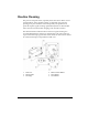
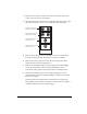
3 Remove the black guide roller under the static brush for easier access to
the printhead mounting screw. There are three inline screws on the outer
plate at the end of the guide roller. Remove the two lower screws and
pull on the tab to slide the center shaft out, releasing the guide roller to
drop down.
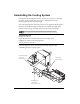
4 Remove the platen roller if you are changing the printhead on print
station #1.
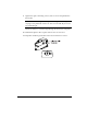
5 Use a Phillips screwdriver to loosen the captive printhead mounting
screw over the top of the printhead.
6 Raise the printhead assembly by the handle to allow the printhead to
drop down away from the bracket.
7 Gently pull the printhead out to the side until the three connectors on the
top of the head are exposed. These connectors are a press fit. Pull up on
each harness to disengage them from the rear of the printhead.
Note: A conductive thermal compound is present on the printhead
mounting blocks.
Use caution when handling printheads to avoid touching the compound.
If the compound comes in contact with any part of the printer other than
the printhead mounting blocks and printheads, clean the compound
from the affected area.
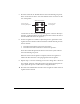
8 Reconnect the three harness connectors to the replacement printhead and
push the head back under the bracket. There are locating pins under the
bracket. Position the printhead over these pins until the printhead seats
flat against the bracket.