FS-C8008N FS-C8008DN Color Laser Printer FS-C8 FS-C8008N 008N Operation Guide
Cautions • • To prevent the printer from tipping over, the optional CA-31B caster kit must be installed when the printer is installed with more than one paper feeder or a duplex unit. For detailed information on the CA-31B caster kit, see page A-11. Do not block the cooling air in and out vents and the exhaust duct against walls or with other objects. If the flow of cooling air is blocked, heat will be built up in the printer, and there will be a risk of fire.
Please read the Operation Guide before using the printer. Keep it close to the printer for easy reference. The sections of this guide and parts of the printer marked with symbols are safety warnings meant to protect the user, other individuals and surrounding objects, and ensure correct and safe usage of the printer. The symbols and their meanings are indicated below.
Caution NO LIABILITY IS ASSUMED FOR ANY DAMAGE CAUSED BY IMPROPER INSTALLATION. Notice on Software SOFTWARE USED WITH THIS PRINTER MUST SUPPORT THE PRINTER'S EMULATION MODE. The printer is factory-set to emulate the PCL. The emulation mode can be changed by following the procedures described in Chapter 3. Notice The information in this guide is subject to change without notification. Additional pages may be inserted in future editions.
IBM PROGRAM LICENSE AGREEMENT THE DEVICE YOU HAVE PURCHASED CONTAINS ONE OR MORE SOFTWARE PROGRAMS ("PROGRAMS") WHICH BELONG TO INTERNATIONAL BUSINESS MACHINES CORPORATION ("IBM"). THIS DOCUMENT DEFINES THE TERMS AND CONDITIONS UNDER WHICH THE SOFTWARE IS BEING LICENSED TO YOU BY IBM. IF YOU DO NOT AGREE WITH THE TERMS AND CONDITIONS OF THIS LICENSE, THEN WITHIN 14 DAYS AFTER YOUR ACQUISITION OF THE DEVICE YOU MAY RETURN THE DEVICE FOR A FULL REFUND.
Agfa Monotype License Agreement 1) "Software" shall mean the digitally encoded, machine readable, scalable outline data as encoded in a special format as well as the UFST Software. 2) You agree to accept a non-exclusive license to use the Software to reproduce and display weights, styles and versions of letters, numerals, characters and symbols ("Typefaces") solely for your own customary business or personal purposes at the address stated on the registration card you return to Agfa Japan.
FCC statement (for users in the United States) This device complies with Part 15 of the FCC Rules. Operation is subject to the following two conditions: (1) This device may not cause harmful interference, and (2) this device must accept any interference received, including interference that may cause undesired operation. Note: This equipment has been tested and found to comply with the limits for a Class B digital device, pursuant to Part 15 of the FCC Rules.
Important Notes for Interface connectors Be sure to power off the printer before connecting or disconnecting an interface cable. For protection against static electricity discharge to the printer's internal electronics through the interface connector(s), cover any interface connector that is not in use with the protective cap supplied. Use shielded interface cables. Safety information Laser safety: This printer is certified as a Class 1 laser product under the U.S.
U.S. CDRH regulations The Center of Devices and Radiological Health (CDRH) of the U.S. Food and Drug Administration implemented regulations for laser products on August 2, 1976. These regulations apply to laser products manufactured on and after August 1, 1976. Compliance is mandatory for products marketed in the United States. A label indicating compliance with the CDRH regulations must be attached to laser products marketed in the United States.
Declaration of Conformity for U.S.A. Model name: Color Laser Printer FS-C8008N Trade name: Kyocera Mita Responsible party: Kyocera Mita America, Inc. Address: 225 Sand Road PO Box 40008 Fairfield, New Jersey 07004-0008, U.S.A.
Declaration of Conformity for Australia Manufacturer: Kyocera Mita Corporation Tamaki Plant Manufacturer’s address: 704-19, Nojino, Tamaki-cho, Watarai-gun, Mie-ken 519-0497, Japan declares that the product Product name: Color Laser Printer Model name: FS-C8008N Description of devices: This Page Printer Model FS-C8008N is the 31 ppm (monochrome)/8 ppm (color), A4 size and utilized plane paper; laser; dry toner; etc.
ENERGY STAR® As an ENERGY STAR Partner, we have determined that this product meets the ENERGY STAR guidelines for energy efficiency. The basic objective of the ENERGY STAR Program is to reduce environmental pollution by encouraging the manufacture and sale of equipment that uses energy more efficiently. This printer is equipped with a sleep timer function that conforms with the standards of the ENERGY STAR Program.
Installation Precautions Environment CAUTION • Avoid placing the printer on or in locations which are unstable or not level. Such locations may cause the printer to fall down or fall over. This type of situation presents a danger of personal injury or damage to the printer. ....................................................................................... • Avoid locations with humidity or dust and dirt.
Power Supply/Grounding the Printer WARNING • DO NOT use a power supply with a voltage other than that specified. Avoid multiple connections in the same outlet. These types of situations present a danger of fire or electrical shock... • Plug the power cord securely into the outlet. If metallic objects come in contact with the prongs on the plug, it may cause a fire or electric shock. ...............................................................
Precautions for Use Cautions when Using the Printer WARNING • DO NOT place metallic objects or containers with water (flower vases, flower pots, cups, etc.) on or near the printer. This type of situation presents a danger of fire or electrical shock should they fall inside. .............................................................................................................
Other Precautions • DO NOT place heavy objects on the printer or cause other damage to the printer. • DO NOT open the front cover, turn off the main switch, or pull out the power plug during printing. • During printing, some ozone is released, but the amount does not cause any ill effect to one's health. If, however, the printer is used over a long period of time in a poorly ventilated room or when printing an extremely large number of copies, the smell may become unpleasant.
For More Information... Item Description Installation Guide (paper manual) Describes procedures from printer setup to printing a test page. Quick Reference Guide (paper manual) Describes common information about the printer such as loading paper, understanding messages, etc. This guide can be retained in the plastic pocket at the printer. The following documents are stored in the CD-ROM as PDF documents.
Guide to the Operation Guide This Operation Guide has the following chapters: Chapter 1 Introduction This chapter explains printer features and the names of parts. Chapter 2 Handling Paper This chapter explains the types of paper that can be used with the printer. Chapter 3 Using the Operator Panel This chapter explains the message display, indicators and keys on the operator panel, and how to make various settings from the operator panel.
Contents Contents Chapter 1 1.1 1.1.1 1.1.2 1.1.3 1.1.4 1.2 1.2.1 1.2.2 1.2.3 Features . . . . . . . . . . . . . . . . . . . . . . . . . . . . . . . . . . . . . . . . . . . . . . . 1-2 General . . . . . . . . . . . . . . . . . . . . . . . . . . . . . . . . . . . . . . . . . . . . . . . . 1-2 Hardware . . . . . . . . . . . . . . . . . . . . . . . . . . . . . . . . . . . . . . . . . . . . . . 1-2 Software . . . . . . . . . . . . . . . . . . . . . . . . . . . . . . . . . . . . . . . . . . . . . . .
Contents 3.6.3 3.6.4 3.6.5 3.7 3.7.1 3.7.2 3.7.3 3.7.4 3.7.5 3.8 3.8.1 3.8.2 3.9 3.9.1 3.9.2 3.9.3 3.10 3.10.1 3.10.2 3.10.3 3.10.4 3.10.5 3.10.6 3.10.7 3.10.8 3.10.9 3.10.10 3.10.11 3.11 3.12 3.12.1 3.12.2 3.13 3.13.1 3.13.2 3.13.3 3.13.4 3.13.5 3.13.6 3.13.7 3.13.8 3.13.9 3.13.10 3.13.11 3.13.12 Alternative Emulation for KPDL Emulation . . . . . . . . . . . . . . . . . . . . 3-44 Printing KPDL Errors . . . . . . . . . . . . . . . . . . . . . . . . . . . . . . . . . . . . 3-45 Default Font . . . . . . .
Contents 4.4.6 4.4.7 4.4.8 4.4.9 Paper Jam — Duplexer . . . . . . . . . . . . . . . . . . . . . . . . . . . . . . . . . . . 4-16 Paper Jam — Paper Transfer Unit . . . . . . . . . . . . . . . . . . . . . . . . . . 4-17 Paper Jam — Left Cover . . . . . . . . . . . . . . . . . . . . . . . . . . . . . . . . . 4-22 Paper Jam — Option Stacker/Finisher/Sorter . . . . . . . . . . . . . . . . . . 4-23 Chapter 5 5.1 5.1.1 5.1.2 5.1.3 5.2 5.3 5.3.1 5.3.2 Maintenance Toner Container Replacement . . . . . . . . . .
Chapter 1 Introduction Welcome to the professional color printer from Kyocera Mita. Using the Ecosys Color Printer, you can now print top quality documents at 31 pages per minute for monochrome and 8 pages per minute for color in A4, Letter, and A5 paper sizes. The Kyocera Mita Ecosys Color FS-C8008N/DN Series printers are available in the following two models: Ecosys Color FS-C8008N Basic model of the FS-C8008 Series.
1.1 Features 1.1 Features This section outlines the common major printer features of the FS-C8008N and the FS-C8008DN Ecosys color laser printers. 1.1.1 General Components with an ultra-long product life The main printer components such as the imaging drum, development units, and fuser unit have an ultra-long product life. The imaging drum has been developed using Kyocera’s leading-edge ceramic technology that makes full use of amorphous silicon.
1.1 Features Two expansion slots for hardware interfaces The printer is equipped with two expansion slots for plugging in an optional network interface card and a hard disk. Standard bidirectional parallel interface Ensures high-speed data transfer between the host computer and printer. Memory card slot You can select and read the data in a memory card set in this slot from the printer operator panel.
1.1 Features KPDL3 (Kyocera Printer Description Language 3) The printer uses KPDL3, Kyocera’s implementation of the PostScript page description language Level 3. The printer has 136 fonts that are compatible with Adobe PostScript fonts. (The printer also has 80 PCL fonts.) PDF417 two-dimensional bar codes The printer has the built-in two-dimensional stacked bar codes of PDF 417 (Portable Data File 417).
1.2 Parts and Functions 1.2 Parts and Functions This section provides explanations and illustrations for you to determine the parts and their functions. Try to be familiar with the names and functions of these parts for correct use and optimal performance. 1.2.1 Front Figure 1-1 1 Operator Panel Used to specify printer functions and display the printer operating status. 2 Front Cover When open, this cover gives you access to the internal component for replacing toner containers.
1.2 Parts and Functions Figure 1-2 6 Paper Stopper This stopper, when flipped up, prevents the printed sheet of large size from falling. 7 Face-down Tray This tray receives printouts face down. 8 Power Switch This switch turns printer power on and off. Caution In order to maintain operability and print quality, this printer operates a cooling fan for 30 minutes even after the power is turned off. For this reason, you should not unplug the power cord even after turning off the power.
1.2 Parts and Functions 1.2.2 Internal Figure 1-3 1 Black Toner Container This container holds black (K) toner. You must replace the container when the toner run out. 2 Main Charger Unit This is an electrical component used to transfer the toner onto the drum unit. The main charger unit must be cleaned when you replace the toner container. 3 Yellow Toner Container This container holds yellow (Y) toner. You must replace the container when the toner run out.
1.2 Parts and Functions 7 Waste Toner Box This plastic box collects waste toner for later disposal. The box has a cap which is used to seal the box opening when being disposed of. 8 Fuser Unit The fuser unit fixes the toner permanently on the paper. The fuser becomes very hot during printing. 9 Paper Transfer Unit The paper transfer unit transports paper from the paper source for developing and fixing images.
1.2 Parts and Functions 1.2.3 Rear Figure 1-4 1 Vents Air is purged through these vents to cool down the inside. 2 USB Interface Connector This connector is a USB interface that conforms to the Full-Speed USB 2.0. Use a USB cable between this connector and the USB port on a computer. 3 Memory Card Slot This slot receives a memory card. A memory card can hold fonts, macros, forms, etc., that can be downloaded in the printer’s memory. For details, see Appendix A Options, section A.3.
1.2 Parts and Functions 9 Hard Disk Slot (HDD) This slot holds an optional hard disk for storing print jobs. A Kyocera Mita manufactured hard disk must be used. For details, see Appendix A Options, section A.3.8 Hard Disk on page A-12. 10 Exhaust Duct Air is purged through these vents to cool down the inside. 11 Quick Reference Guide Holder Use this holder to store the included Quick Reference Guide for easy access.
Chapter 2 Handling Paper The printer can use a variety of media in various sizes. However, any media you will choose to use with the printer must be in accordance with the guidelines and specifications in this chapter. Use of paper not satisfying these guidelines and specifications may cause problems such as frequent paper jams, poor quality printing, and possible damage to the printer mechanism.
2.1 General 2.1 General The Ecosys Color FS-C8008 Series printers are designed for high-grade bond (copy) paper, like those widely used for ordinary xerographic copiers. The printers will also support other types of paper as long as they meet the standards explained in this chapter. Selecting the right paper is very important. Use of unsuitable paper can cause paper jams, misfeed, curling, poor print quality, and even worse, printer damage.
2.1 General Item Values Direction of grain Long grain Pulp content 80 % or more Table 2-1 (Continued) † 2.1.3 Paper of 135 to 220 g/m² thick should be A4 or Letter size and fed laterally. Minimum and Maximum Paper Sizes 148 mm 5-13/16 inches The minimum and maximum paper sizes are as follows. For non standard paper such as cut-sheet, the MP (multi-purpose) tray must be used. Minimum Paper Size 458 mm 18 inches 80 mm 3-1/8 inches Maximum Paper Size 310 mm 12-3/16 inches Figure 2-1 2.1.
2.2 Selecting the Right Paper 2.2 Selecting the Right Paper To get clean, crisp printouts from laser printers all the time, select high-quality printer paper that meets the printer’s requirements. Laser printers use laser beams, electrostatic discharge, toner, and heat, all of which affect the paper. Furthermore, paper slide, bends, and twists as it passes through laser printers during printing. Therefore, printer paper must be able to withstand such great stress.
2.2 Selecting the Right Paper MP tray Size Cassette or MP tray Size Ledger Wide 310 × 440 mm ISO C4 229 × 324 mm Statement 5-1/2 × 8-1/2 inches Oficio II 8-1/2 × 13 inches Hagaki 100 × 148 mm 8K 273 × 394 mm Oufuku Hagaki 148 × 200 mm 16K 197 × 273 mm Youkei 2 114 × 162 mm Youkei 4 105 × 235 mm Custom 80 × 148 mm to 310 × 458 mm Table 2-3 (Continued) 2.2.2 Paper properties Smoothness Paper should have a smooth, uncoated surface.
2.2 Selecting the Right Paper U. S. Bond Weight (lb) Europe Metric Weight (g/m²) 28 105 32 120 34 128 36 135 39 148 42 157 43 163 47 176 53 199 Table 2-4 (Continued) Thickness (Caliper) Thick paper is called high-caliper paper and thin paper is called low-caliper paper. Paper used by the printer should be neither too thick nor too thin. If you encounter paper jam, multiple-sheet feed, or too light printing problems, the paper may be too thin.
2.2 Selecting the Right Paper 2.2.3 Other properties of paper Porosity The density of paper structure, which indicates the compactness of the fiber bonding. It is also the characteristic that allows air to pass through paper (i.e., air permeability). Stiffness The ability of paper to resist deformation under stress. In the printer, limp paper can buckle and too stiff paper can bind. Both conditions result in paper jams. Curl Most paper naturally tends to curl one way.
2.3 Loading Paper 2.3 Loading Paper The following explains the procedure for loading paper in the cassette and the MP tray. Fan the media (paper/transparencies), then tap it on a level surface to avoid media jams or skewed printing. Caution Figure 2-2 2.3.1 Loading Paper into the Cassette Perform the following procedure to load paper into the cassette. 1 2 Pull out the paper feed cassette until it stops. Lift the paper feed roller located on the right side of the cassette upright.
2.3 Loading Paper 3 Adjust the position of the paper guides according to the size of the paper you will use. To move the paper guides, press the green-colored knobs. Paper Stopper Paper Guide Figure 2-4 4 Align the paper stopper correctly with the markings in the cassette that match the paper size: Figure 2-5 5 Square the edges of the paper and insert into the paper feed cassette. Be sure that the paper does not exceed the paper limit indicators.
2.3 Loading Paper 2.3.2 Loading Paper into the MP (Multi-Purpose) Tray Perform the following procedure to load paper into the MP tray. 1 Open the MP tray located on the right side of the printer. MP Tray Figure 2-7 2 Adjust the position of the paper guides according to the size of the paper you will use. Paper Guide Paper Guide Figure 2-8 3 Square the edges of the paper and insert into the MP tray. Figure 2-9 4 Set the MP tray paper size on the printer’s operator panel.
2.4 Special Paper 2.
2.4 Special Paper Transparency Transparencies for overhead projectors must withstand the heat of fusing during the printing process. The recommended transparency product is as follows: 3M CG3700 (Letter, A4) Transparencies must be placed on the MP (multi-purpose) tray with the long edge towards the printer. To avoid problems, stack transparencies face up on the face-up tray. MP Tray Figure 2-10 When unloading transparencies (e.g.
2.4 Special Paper When the label paper has extra margin around the label’s outside edges that correspond to the margins of the printable area, do not remove the extra top sheet from the carrier sheet until printing is finished. Allowed Not allowed Top sheet Carrier sheet Figure 2-12 When selecting labels, make sure to use only those meeting the following requirements: Item Value Top sheet weight 44 to 74 g/m² (12 to 20 lb) Total weight 104 to 151 g/m² (28 to 40 lb) Top sheet thickness 0.
2.4 Special Paper Envelopes Envelopes must be fed manually. Since the composition of an envelope is more complex than that of ordinary paper, it is not always possible to ensure consistent printing quality over the entire envelope surface. Normally, envelopes have a diagonal grain direction. See section Grain on page 2-6. This direction can easily cause wrinkles and creases when envelopes pass through the printer.
Chapter 3 Using the Operator Panel This chapter provides the information you need to configure the Ecosys Color printer. In general you need to use the operator panel only to make default settings. You can make most changes to the printer settings using the printer driver trough the application software. Changes to printer settings made using a software application override changes made using the operator panel.
3.1 Understanding the Operator Panel 3.1 Understanding the Operator Panel The operator panel on the top of the printer has a 2-line by 16-character liquid crystal display (LCD), eight keys, and three indicators (LED). Figure 3-1 Messages that appear on the display and functions of indicators and keys are explained in the sections that follow. 3.1.
3.1 Understanding the Operator Panel Message Meaning Sleeping The printer is in sleep mode. The printer wakes from sleep mode whenever a key on the operator panel is pressed, the cover is opened or closed, or a print job is received. The printer then warms up and goes on-line. For details on sleep mode, see Sleep Timer Timeout Time on page 3-91. Cancelling data Jobs inside the printer are being canceled. To cancel a job, see Section 3.1.3 Keys on page 3-6.
3.1 Understanding the Operator Panel Paper Size Indicator (SIZE) This indicator indicates: • • While the printer is in standby, the paper size of the cassette. The default paper cassette is determined by the operator panel keys. For details, see Section 3.10 Paper Handling on page 3-69. While the printer is printing, the paper size used to format the document to print by the application software.
3.1 Understanding the Operator Panel Paper Type Indicator (TYPE) This indicator shows the paper type defined for the current paper casette. The paper type can be manually defined using the operator panel. For more information, see Section 3.10 Paper Handling on page 3-69.
3.1 Understanding the Operator Panel 3.1.3 Keys The operator panel keys are used to configure the printer operation. Note that certain keys have the secondary function. Note The printer has a parallel, serial, and an optional network interface. Configuration to the printer settings made with these keys affect only one of these interfaces that is currently active (indicated by the INTERFACE indicator on the message display). See Interface Indicator (INTERFACE) on page 3-3.
3.1 Understanding the Operator Panel MENU Key The MENU key lets you enter the menu system to change the setup and printing environment of the printer. Pressing this key during a menu selection will terminate the selection and return the printer to the normal operation. Arrow Keys The four arrow keys are used in the menu system to access a desired item or enter numeric values. The arrow key with the question mark (?) may be pressed when the paper jam message has appeared on the message display.
3.2 Using the Menu Selection System 3.2 Using the Menu Selection System 3.2.1 Menu Selection System This section explains how to use the menu selection system. The MENU key on the operator panel allows you to use the menu to set or change the printer environment such as the number of copies to print, emulation, etc., to your specific needs. Settings can be made when Ready is indicated on the printer message display.
3.2 Using the Menu Selection System Selecting a Menu The mode selection menu is hierarchical. Press the U or V key to display the desired menu. • If the selected menu has a sub-menu, > is displayed after the menu. Paper Handling > Indicates that there is a sub-menu Press the Z key to move to the sub-menu or Y key to go back. • > is displayed before the sub-menu.
3.2 Using the Menu Selection System 3.2.2 Menu System Road Map The following is the hierarchy diagram of the menu selection system of the printer. For details about menu selection operations, see page 3-8. Ready PAR A4 PLAIN MENU Key Print Menu Map Print Status Page e-MPS > >Quick Copy >Private/Stored >Print VMB Data >List of VMB >List of Code JOB >e-MPS > Configuration >>Quick Copy 32 >>Temp. Code JOB Size 1550MB >>Perm.
3.2 Using the Menu Selection System Continued Interface > Parallel Interface USB Interface > Network Interface > Serial Interface > Option >Parallel I/F Nibble (high) >NetWare Off >NetWare On > >>NetWare Frame Auto >TCP/IP Off >TCP/IP On > >>DHCP Off >>DHCP On >EtherTalk Off >EtherTalk On >>IP Address 000.000.000.000 >Network Status Page Off >Network Status Page On >>Subnet Mask 000.000.000.000 >>Gateway 000.000.000.000 >Baud Rate 9600 >Data Bits 8 >Stop Bits 1 >Parity None >Protocol DTR (pos.
3.2 Using the Menu Selection System Continued Font > >Font Select Internal >Font Select Option > >Code Set IBM PC-8 >> I000 > >>Courier Regular >>Courier Dark >List of Internal Fonts >>Letter Gothic Regular Gothic >>Letter Dark >List of Option Fonts >>Size 012.00 point(s) >>Pitch 10.
3.
3.2 Using the Menu Selection System Continued Life Counters > >Total Print >New Toner [C] Installed >New Toner [M] Installed >New Toner [Y] Installed >New Toner [K] Installed Others > >MSG Language English >Form Feed Time Out 000sec. >Sleep Timer > 030 min. >>Sleep Mode On >>Sleep Mode Off >Print HEX-DUMP >Printer Reset >Resource Prot. Off >Buzzer Off >Buzzer On >Auto Continue Mode Off >Auto Continue > Mode On >>Auto Continue Timer 030sec.
3.3 Menu Map and Status Pages 3.3 Menu Map and Status Pages This section explains the procedure for printing the printer’s internal information using the menu selection system. The menu map is usefull as a reference to guide yourself through the menu selection system. The status page is a list of parameters and settings for most basic printer configurations. You may be required to produce a status page when requesting service to the printer. 3.3.
3.
3.3 Menu Map and Status Pages 3.3.2 Printing a Status Page You can check the printer’s current status, including available memory space and option settings by printing a status page. 1 2 Press the MENU key. Press the U or V key repeatedly until Print Status Page appears. Print Status Page 3 Press the ENTER key. A question mark (?) appears. Print Status Page ? 4 Press the ENTER key again. The message Processing appears and the printer prints a status page.
3.3 Menu Map and Status Pages Understanding the Status Page The numbers in the following diagram refer the items explained below the diagram. The items and values on the status page may vary depending on the printer’s firmware version.
3.
3.4 e-MPS 3.4 e-MPS e-MPS is an abbreviation for ‘enhanced-Multiple Printing System’ which implements the following functions that are available from the printer driver: • • Job Retention Job Storage In either job mode, when printing a document, the print data is transferred from the computer to the printer then stored on the printer’s hard disk. Since copies of the document are printed using the stored data, printing is performed faster with less computer spooling time and less network traffic.
3.4 e-MPS Job Storage Job storage stores print jobs either temporarily or permanently, or in virtual mailboxes, as you click an appropriate radio button on the printer driver when printing from a computer. Virtual Mailbox Virtual mailbox is part of Job Storage, which stores print jobs on the hard disk without printing. It enables you to retrieve jobs later from the operator panel or the KM-NET Printer Disk Manager utility in the CD-ROM.
3.4 e-MPS Printing Additional Copies using Quick Copy To print additional copies of a job stored in the printer: 1 2 Press the MENU key. Press the U or V key repeatedly until e-MPS > appears. e-MPS 3 4 > Press the Z key. Press the U or V key repeatedly until >Quick Copy appears followed by the user name (Harold, in this example). The user name is assigned at printing using the printer driver. >Quick Copy Harold 5 Press the ENTER key. A blinking question mark (?) appears before the user name.
3.4 e-MPS Deleting a Quick Copy Job All quick copy jobs are automatically deleted when the printer is turned off. If you desire to explicitly delete a stored quick copy job, proceed as follows: 1 Follow steps 1 through 8 in the above section to let the title of the job to be deleted displayed. 2 When the title of the job to be deleted is displayed, e.g. Report, below, press the ENTER key. The cursor below the copy count starts to blink.
3.4 e-MPS 3.4.3 Printing a Private Print/Job Retention In private printing, you can specify that a job is not printed until you release the job from the operator panel. At sending the job from the application software, you can specify a 4-digit access code in the printer driver. The job is released for printing by entering the access code on the operator panel. Thus, this function ensures confidentiality of the print job.
3.4 e-MPS 9 Press the ENTER key. The ID input line appears. Enter the four-digit access code entered in the printer driver and press the ENTER key. >Agenda ID 0000 To enter the ID, press the Y or Z key to move the cursor to the number to be changed and then enter the correct number by pressing the U or V key. 10 You can set the number of copies to be printed. To increase the copy count, press the U key; to decrease the copy count, press the V key.
3.4 e-MPS Printing a Code Job Install the KM-NET Job Manager software from the CD-ROM supplied with the printer. To do this, from the CD-ROM Main Menu, select Printer Utilities > Install KM-NET Job Manager. 1 Browse through Windows Start > Programs > KYOCERA MITA > KM-Net > Job Manager. 2 3 Enter the password for the software. Job Manager will start. Click the Add printer icon (below). Select the Local or Network port.
3.4 e-MPS Printing a List of Code Jobs If you select Permanent Job Storage on the printer driver, you can have a List of Code Job printed using the operator panel. 1 2 Press the MENU key. Press the U or V key repeatedly until e-MPS > appears. e-MPS 3 4 > Press the Z key. Press the U or V key repeatedly until >List of Code JOB appears. >List of Code JOB 5 Press the ENTER key. A question mark (?) appears. >List of Code JOB ? 6 Press the ENTER key again.
3.4 e-MPS 3.4.4 Retrieving Jobs from Virtual Mailbox (VMB) To retrieve the jobs posted in the virtual mailbox, proceed as follows. 1 2 Press the MENU key. Press the U or V key repeatedly until e-MPS > appears. e-MPS 3 4 > Press the Z key. Press the U or V key repeatedly until >Print VMB Data appears. The virtual mailbox number will also appear.
3.4 e-MPS 4 Press the U or V key repeatedly until >List of VMB appears. >List of VMB 5 Press the ENTER key. A question mark (?) appears. >List of VMB ? 6 Press the ENTER key again. The printer prints a list of jobs currently posted in the virtual mailboxes as shown in Figure 3-6 below.
3.4 e-MPS 3.4.5 Changing e-MPS Configuration You can change the following parameters for e-MPS operation: • • • • Note Maximum number of Quick Copy/Proof-and-Hold jobs Maximum space assigned to temporary code jobs Maximum space assigned to permanent code jobs Maximum space assigned to virtual mailboxes The total amount of storage areas specified must not exceed the total size of the hard disk. Otherwise, you may only be able to accommodate print jobs of a smaller amount of print jobs than specified.
3.4 e-MPS 10 Press the MENU key. The display returns to Ready. Maximum Space Assigned to Temporary Code Jobs This changes the hard disk space that holds temporary code jobs. You can change the maximum space from 0 to 9999 (megabytes). The actual maximum size depends on the size of free hard disk space, however. The default size is 1/6 of the total hard disk space, rounded off in unit of 50 MB. For example, if the total hard disk space is 10 GB, the default size is 1550 MB. 1 2 Press the MENU key.
3.4 e-MPS Maximum Space Assigned to Permanent Code Jobs This changes the hard disk space that holds permanent code jobs. You can change the maximum space from 0 to 9999 (megabytes). The actual maximum size depends on the size of free hard disk space, however. The default size is 1/6 of the total hard disk space, rounded off in unit of 50 MB. For example, if the total hard disk space is 10 GB, the default size is 1550 MB. 1 2 Press the MENU key. Press the U or V key and select e-MPS >.
3.4 e-MPS Maximum Space Assigned to Virtual Mailboxes (VMB) This changes the hard disk space for virtual mailboxes. You can change the maximum space from 0 to 9999 (megabytes). The actual maximum size depends on the size of free hard disk space, however. The default size is 1/6 of the total hard disk space, rounded off in unit of 50 MB. For example, if the total hard disk space is 10 GB, the default size is 1550 MB. 1 2 Press the MENU key Press the U or V key and select e-MPS >.
3.5 Changing the Interface Parameters 3.5 Changing the Interface Parameters The printer is equipped with both a parallel and USB interfaces. Option serial interface board kit and network interface card can also be installed. Various printing environment parameters such as the default emulation can be changed independently on different interfaces by using the printer’s menu selection system. Select the interface to apply the changes in the procedure described below.
3.5 Changing the Interface Parameters 8 Press the U or V key to scroll through the following communication modes: Nibble (high) Auto Normal High Speed 9 10 3.5.2 When the desired communication mode is displayed, press the ENTER key. Press the MENU key to exit the menu selection. Changing Serial Interface Parameters This section applies to the printers having the option serial interface board kit (IB-11) installed.
3.5 Changing the Interface Parameters Pressing the U or V key toggles through the serial parameters as follows. To change the serial parameter, press the ENTER key. Use the U or V key to change the value or selection. Range 1200, 2400, 4800, 9600 (Default), 19200, 38400, 57600, 115200 >Baud Rate 9600 7 or 8 (Default) >Data Bits 8 1 (Default) or 2 >Stop Bits 1 None (Default), Odd, Even, or Ignore >Parity None >Protocol DTR(pos.)&XON DTR(pos.
3.5 Changing the Interface Parameters 3.5.3 Changing Network Interface Parameters This printer supports TCP/IP, NetWare and EtherTalk protocols. In addition, you can install the optional network interface card in the printer’s extension slot (OPT).
3.5 Changing the Interface Parameters 6 Press the Z key. One of the following menus is indicated. To change settings for the item, press the ENTER key. Use the U or V key to change the value or selection. Range >NetWare On > >TCP/IP On > >Network Status Page Off 8 Set this item to On when you connect to a network using TCP/IP. Submenu (>) has items including DHCP, IP address, subnet mask address, and gateway address. To resolve IP address for the network card, see 3.5.4 Resolving IP Address below.
3.5 Changing the Interface Parameters 3.5.4 Resolving IP Address To connect the printer to the network using TCP/IP protocol, you must set the IP address on the printer. The IP address must be unique to the printer and should be obtained from your network administrator. 1 Activate TCP/IP protocol in the manner described above. >TCP/IP On 2 > Enter the submenu by pressing the Z key. Each time you press the U or V key, the selection changes as shown below. >>DHCP Off >>IP Address 000.000.000.
3.5 Changing the Interface Parameters Printing a Network Interface Status Page You can have your printer print out a network status page when the printer prints the status page. The network status page shows the network addresses, and other information under various network protocols about the network interface card. The default setting is Off (print disable). Printing out a network interface status page may not be possible with the optional network interface card.
3.5 Changing the Interface Parameters 8 9 Press the ENTER key again. Press the MENU key. The display returns to Ready. The printer prints a network status page as an example shown in Figure 3-7 below.
3.6 Making Default Settings 3.6 Making Default Settings Using the operator panel, you can set the default for the following items. Note default settings made using the operator panel may be overridden by the printer driver settings and application software. 3.6.1 Default Emulation You can change the emulation mode and character code set for the current interface.
3.6 Making Default Settings 3.6.2 KC-GL Pen Width and Color The KC-GL emulation mode enables you to set the pen widths in dots, individual pen colors for pen numbers 1 to 8, and the KC-GL page size. 1 2 Press the MENU key. 3 If the current emulation is other than KC-GL, press the ENTER key. A blinking question mark (?) appears. 4 Press the U or V key repeatedly until KC-GL appears. Press the ENTER key. Press the U or V key repeatedly until Emulation appears on the message display.
3.6 Making Default Settings 12 To change the page size, press the ENTER key. A blinking question mark (?) appears. >KC-GL Page Set ? [A2] 3.6.3 13 Press the U or V key repeatedly until the desired page size (A2, A1, A0, B3, B2, B1, B0, and SPSZ) appears. The SPSZ command sets the paper edge limits to the dimensions of a standard paper size. See this command explained in the Programming Manual in the CD-ROM. Press the ENTER key to set the page set you just selected. 14 Press the MENU key.
3.6 Making Default Settings 3.6.4 7 8 Press the U or V key until the desired alternative emulation appears. 9 Press the MENU key. The display returns to Ready. Press the ENTER key. Printing KPDL Errors The printer can print error descriptions when printing error occurs during KPDL emulation. The default is Off — the printer does not print KPDL errors. 1 2 Press the MENU key. Press the U or V key repeatedly until Emulation > appears. Emulation PCL 6 3 > Press the ENTER key.
3.6 Making Default Settings 3.6.5 Default Font You can select the default font for the current interface. The default font can be one of the internal fonts or a font that is downloaded to the printer memory or stored on memory card or hard disk. In this menu, you can also set the type and pitch for Courier and Letter Gothic; as well as to print a font list. 1 2 Press the MENU key. Press the U or V key repeatedly until Font > appears. Font 3 > Press the Z key.
3.6 Making Default Settings Selecting Regular or Dark Courier/Letter Gothic Courier or Letter Gothic font thickness can be selected as Regular or Dark. In the procedure below, it is assumed that Courier is selected. The procedure is the same for Letter Gothic. 1 2 Press the MENU key. Press the U or V key repeatedly until Font > appears. Font 3 > Press the Z key. Press the U or V key until >Font Select > appears. >Font Select Internal 4 5 > Make sure that Internal is displayed and press the Z key.
3.6 Making Default Settings Changing the Default Font Size You can change the size of the default font. If you selected a proportional font, the character size can also be changed. 1 2 Press the MENU key. Press the U or V key repeatedly until Font > appears. Font 3 > Press the Z key. Press the U or V key until >Font Select > appears. >Font Select Internal 4 5 > Make sure that Internal is displayed and press the Z key. Press the U or V key repeatedly until >>Size appears. >>Size 012.
3.6 Making Default Settings Character Pitch for Courier/Letter Gothic You can set the character pitch for fixed fonts when the default font is Courier or Letter Gothic. 1 2 Press MENU key. Press the U or V key repeatedly until Font > appears. Font 3 > Press the Z key. Press the U or V key until >Font Select > appears. >Font Select Internal 4 5 > Make sure that Internal is displayed and press the Z key. Press the U or V key repeatedly until >>Pitch appears. >>Pitch 10.
3.6 Making Default Settings Setting the Code Set You can change the character code set. Available character code sets vary depending on the current font. (The default is IBM PC-8.) 1 2 Press the MENU key. Press the U or V key repeatedly until Font > appears. Font 3 4 > Press the Z key. Press the U or V key repeatedly until >Code Set appears. >Code Set IBM PC-8 5 Press the ENTER key. A blinking question mark (?) appears.
3.6 Making Default Settings Printing Lists of Fonts To help you decide in selecting a font, you can printout lists of the internal fonts or the optional fonts including downloaded fonts. Samples for font lists are shown in Figure 3-8 on page 3-52. 1 2 Press the MENU key. Press the U or V key repeatedly until Font > appears. Font 3 4 > Press the Z key. Press the U or V key repeatedly until >List of Internal Fonts or >List of Option Fonts appears. >List of Internal Fonts 5 Press the ENTER key.
3.
3.7 Pagination 3.7 Pagination In Page Set menus, you can set the number of copies, page orientation, and other settings regarding pagination. 3.7.1 Number of Copies You can set the number of copies of each page to be printed for the current interface. The number of copies can be set between 1 and 999. 1 2 Press the MENU key. Press the U or V key repeatedly until Page Set > appears. Page Set 3 4 > Press the Z key. Press the U or V key repeatedly until >Copies appears.
3.7 Pagination 3.7.2 Print Orientation You can select portrait (upright) or landscape (sideways) page orientation. Portrait Orientation Landscape Orientation A A Figure 3-9 1 2 Press the MENU key. Press the U or V key repeatedly until Page Set > appears. Page Set 3 4 > Press the Z key. Press the U or V key repeatedly until >Orientation appears. >Orientation Portrait 5 Press the ENTER key. A blinking question mark (?) appears.
3.7 Pagination 3.7.3 Page Protect Mode The Page Protect Menu does not normally appear, however, Page Protect will be forcibly set to On if a print overrun error occurs due to insufficient printer memory. When this has happened, be sure to reset Page Protect to Auto (default) in order to maintain the optimum use of printer memory. 1 2 Press the MENU key. Press the U or V key repeatedly until Page set > appears. Page set 3 4 > Press the Z key.
3.7 Pagination 3.7.4 Linefeed (LF) Action This procedure instructs the printer what to do when it receives a linefeed code (0AH). • • • 1 2 LF Only: Linefeed is performed (Default). CR and LF: A linefeed and carriage return are performed. Ignore LF: The linefeed is ignored. Press the MENU key. Press the U or V key repeatedly until Page Set > appears. Page Set 3 4 > Press the Z key. Press the U or V key repeatedly until >LF Action appears. >LF Action LF only 5 Press the ENTER key.
3.7 Pagination 3.7.5 Carriage-Return (CR) Action This procedure instructs the printer what to do when it receives a carriage-return code (0DH). • • • 1 2 CR Only: A carriage-return is performed (Default). CR and LF: A linefeed and carriage return are performed. Ignore CR: The carriage-return is ignored. Press the MENU key. Press the U or V key repeatedly until Page Set > appears. Page Set 3 4 > Press the Z key. Press the U or V key repeatedly until >CR Action appears.
3.8 Setting Print Quality 3.8 Setting Print Quality The printer features the Print Quality menu which lets you select: • • 3.8.1 Tone mode (Normal and Fine) Gloss mode (Low and High) Tone Mode The Tone Mode selects the way the printer handles a pixel for representing the color and halftoning for each pixel — Normal or Fine. The Fine tone mode uses four-bit smooth halftone for photographs, image, etc.; and the Normal tone mode uses a two-bit halftone for text, solid objects, etc.
3.8 Setting Print Quality 3.8.2 Gloss Mode The gloss mode, when set to High, increases the effect of glossiness in printing by reducing the printing speed by half. The gloss mode is not available when Transparency is selected as the paper type setting. Depending on the paper used, printing in gloss mode may cause wrinkle in paper. To reduce wrinkle, try using thicker paper. Note The default gloss mode is Low. To confirm or change the gloss mode, proceed as follows: 1 2 Press the MENU key.
3.9 Operating the Storage Device 3.9 Operating the Storage Device The printer supports three types of storage device; memory card, option hard disk, and RAM disk. The memory card and option hard disk are installed into the dedicated slots of the printer. The RAM disk is an allocated part of the printer’s memory. If the optional hard disk is installed in the printer, the e-MPS function will be available. For details, see e-MPS on page 3-20. The basic operations of each storage device are the same.
3.9 Operating the Storage Device 6 Press the ENTER key. Processing appears and the reading of data from the memory card starts. When completed, Processing disappears. >Read Fonts Processing 7 Press the MENU key. The display returns to Ready. Reading Data You can print out the data in the memory card. To read the data saved on the memory card and print it out, proceed as follows. 1 2 Press the MENU key. Press the U or V key repeatedly until Memory Card > appears.
3.9 Operating the Storage Device Writing Data Data can be written to a memory card until no space is left for storing. When writing to a memory card, a name is assigned to the file automatically. You can use the procedure explained in the section Printing a List of Data Names (Partitions) on page 3-65 to print a list of data names for confirmation. To write data to a memory card, proceed as follows. Note First check that the memory card is properly formatted.
3.9 Operating the Storage Device The file is written onto the memory card given a destination name (also referred to as a partition name) which the printer automatically assigns one after another as follows: DataS001 (first data), DataS002 (second data), DataS003 (third data)... FS-C8008N Page Printer WRITE INFORMATION Figure 3-10 Partition Type: Partition Name: Write Partition Length: Others: Type of data written (currently only type 2 is supported). The destination name of data written to the card.
3.9 Operating the Storage Device 4 Press the U or V key repeatedly until >Delete Data appears. The data name also appears (Report, in this example). >Delete Data Report 5 Press the ENTER key. A blinking question mark (?) appears before the data name. >Delete Data ?Report 6 7 Press the U or V key to display the desired data name. Press the ENTER key. Processing appears and the data is deleted from the memory card. The display returns to Ready.
3.9 Operating the Storage Device 6 Press the ENTER key. Processing appears and formatting of the memory card starts. When the formatting is successfully completed, the printer automatically prints out a format information page, which allows you to check the memory card for proper formatting. FS-C8008N Page Printer FORMAT INFORMATION Figure 3-11 Format information page includes the following items: Capacity: Used Space: Free Space: The total size of the memory card.
3.9 Operating the Storage Device 5 Press the ENTER key. A question mark (?) appears. >List of Partitions ? 6 Press the ENTER key. Processing appears and the printing of the list starts. FS-C8008N Page Printer PARTITION LIST Device Information Partition Information Figure 3-12 The printout (example above) includes the following information: Device Name/Number: Capacity: Used Space: Free Space: Partition Name: Partition Size: Partition Type: MEMORY CARD/A is indicated for the memory card.
3.9 Operating the Storage Device 3.9.2 Using the Option Hard Disk Installing the option hard disk into the printer allows you to perform the following operations on the hard disk. • • • • • Reading data Writing data Deleting data Formatting hard disk Printing a list of data names (partitions) When an option hard disk is inserted into the printer for the first time, it must be formatted before use.
3.9 Operating the Storage Device • • Note • The RAM disk can not be used when an option hard disk is installed. The RAM disk stores data only temporarily. When the printer is reset or turned off, the stored data will be erased. The RAM disk is allocated within the printer's memory available to users. If the size of the RAM disk is set too large, the printing speed may decrease or the memory may become insufficient.
3.10 Paper Handling 3.10 Paper Handling This section explains how to change mode for the MP (multi-purpose) tray, the paper size and type for each paper source, mode for the option sorter, and how to select the paper source and paper destinations. 3.10.1 MP Tray Mode The MP tray can be used in either of two modes — Cassette or First. The MP tray feed paper differently depending on the mode: • • Cassette Mode (default) The MP tray acts in the same manner as other paper source.
3.10 Paper Handling 3.10.2 Setting MP Tray Paper Size When you use the MP tray in cassette mode, you should set the MP tray size to the paper size that is used to format the job to print. If the sizes do not match, printing will not be performed on the correct size paper. The default setting is Letter size for the U.S. and Canada and A4 for other countries. For more information about the paper sizes that you can feed from the MP tray, see Chapter 2 Handling Paper.
3.10 Paper Handling 6 Press the U or V key to display the desired paper size. The message display toggles through the following paper sizes: A4 Executive Letter-R Letter Legal Ledger Ledger Wide A3 Wide A3 B4 Custom C4 Hagaki Oufukuhagaki Oficio II Statement Folio Youkei 2 Youkei 4 8K 16K Monarch Business Comm. #9 Comm. #6 3/4 DL C5 A6 B6 A5 B5 ISO B5 A4-R 7 When the desired paper size is displayed, press the ENTER key. The paper size is set for the MP tray.
3.10 Paper Handling 3.10.3 Setting the MP Tray Paper Type By setting a paper type (plain, recycled, etc.) to the MP tray, you can select the paper on the MP tray according to the paper type you command on the printer driver. The default setting is plain paper. For more information about paper types that can be fed from the MP tray, see Chapter 2 Handling Paper. 1 2 Press the MENU key. Press the U or V key repeatedly until Paper Handling > appears. Paper Handling > 3 4 Press the Z key.
3.10 Paper Handling 3.10.4 Setting the Cassette Paper Type By setting a paper type (plain, recycled, etc.) to the paper cassette, you can automatically select the paper in the paper cassette according to the paper type you command on the printer driver. The default setting is plain paper for all paper cassettes. For more information about paper types that you can feed from the paper cassette, see Chapter 2 Handling Paper. 1 2 Press the MENU key.
3.10 Paper Handling 3.10.5 Selecting the Paper Feed Source You can select the paper source using the operator panel, from which the printer feeds paper as the default. If an optional paper feeder(s) is installed, it is also available for the default paper source. 1 2 Press the MENU key. Press the U or V key repeatedly until Paper Handling > appears. Paper Handling > 3 4 Press the Z key. Press the U or V key repeatedly until >Feed Select appears.
3.10 Paper Handling 3.10.6 Duplex Printing (FS-C8008DN) The FS-C8008DN is equipped with the PD-800 duplex unit as a standard feature. The Paper Handling menu on the operator panel provides you with activating the duplexer for printing both sides of paper. You can also select the direction the duplex printed pages are bound — short or long edge binding. See Figure 3-13 below.
3.10 Paper Handling To select duplex printing and binding from the operator panel, use the following procedure: 1 2 Press the MENU key. Press the U or V key repeatedly until Paper Handling > appears. Paper Handling > 3 4 Press the Z key. Press the U or V key repeatedly until >Duplex Mode appears. >Duplex Mode None 5 To activate duplex printing, press the ENTER key. A blinking question mark (?) appears. >Duplex Mode ?None 6 Press the U or V key to display the desired binding mode.
3.10 Paper Handling 3.10.7 Overriding Difference between A4 and Letter When the Override A4/LT is turned on using the operator panel, the printer ignores the difference between A4 and Letter paper sizes. Printing is performed without an error message even if the actual paper size in the current cassette differs from the paper size formatting the job. By default, this feature is off. To confirm and turn on the Override A4/LT, proceed as follows: 1 2 Press the MENU key.
3.10 Paper Handling 3.10.8 Creating Custom Paper Types The Type Adjust menu on the operator panel may be used to create a user-defined paper type for the printer. Custom paper types allow you to optimize printing parameters such as the fuser temperature best suited for the paper property. It also enables the printer to automatically select the paper cassette in which the custom paper is loaded as commanded by the printer driver Up to eight custom user settings may be registered on the operator panel.
3.10 Paper Handling 7 When the paper type to be customized is displayed, press the ENTER key. Proceed to the next procedure. Step 2. Selecting the Paper Weight 1 2 Complete Step 1. above. 3 Press the U or V key repeatedly until >>Paper Weight appears. Press the Z key. >>Paper Weight Normal 4 Press the ENTER key. A blinking question mark (?) appears.
3.10 Paper Handling 6 When the desired fuser mode is displayed, press the ENTER key. Proceed to the next step. Enabling or Disabling Duplex Printing for Custom Paper Type This parameter is valid for the FS-C8008DN printer which is equipped with the duplexer as a standard feature. When this parameter is disabled for a Custom type, the printer does not duplex print when the custom size is selected for the paper type in a print job. By default, duplex printing is enabled for custom paper types.
3.10 Paper Handling 4 Press the U or V key repeatedly until >Reset Type Adjust appears. >Reset Type Adjust 5 To reset all custom paper types, press the ENTER key. A question mark (?) appears. >Reset Type Adjust ? 6 Press the ENTER key. All customized paper types, including weight and duplex printing capability, will be reset to the default. The display returns to Ready. 3.10.
3.
3.10 Paper Handling These modes are depicted in Table 3-4 which follows: Mode Description Sorter mode Copy 1 (1-50 pages) 1 Copy 2 (1-50 pages) 2 Copy 3 (1-50 pages) 3 Copy 4 (1-50 pages) 4 5 ..... Collator mode 200 copies of page 1 1 200 copies of page 2 2 200 copies of page 3 3 200 copies of page 4 4 5 ..... Mailbox mode Last page 1 2 3 4 5 The sorter mode sorts the output pages by copy as shown in the example. This mode is useful when you need several independent copies of a document.
3.10 Paper Handling 3 4 Press the Z key. Press the U or V key repeatedly until >Sorter Mode appears. >Sorter Mode Sorter 5 To change mode, press the ENTER key. A blinking question mark (?) appears. >Sorter Mode ? Sorter 6 Press the U or V key to display the desired sorter mode. The message display toggles through the following: Sorter (default) Collator Mail box 7 When the desired sorter mode is displayed, press the ENTER key. The sorter mode is changed.
3.11 Selecting Monochrome or Color Printing 3.11 Selecting Monochrome or Color Printing You can use the Color Mode menu on the operator panel to select the Monochrome or Color printing mode. By default, the printer is set to print in color mode. To change it to monochrome mode, proceed as follows: 1 Press the MENU key. 2 Press the U or V key repeatedly until Color Mode appears. Color Mode Color 3 To change color mode, press the ENTER key. A blinking question mark (?) appears.
3.12 Reading Life Counters 3.12 Reading Life Counters You can display the total number of pages printed by your printer whenever it is necessary. The total number of printed pages can also be checked on the status page. See Section 3.3.2 Printing a Status Page on page 3-17. For proper maintenance scheduling, you need to reset the toner counter using this menu each time a new toner container is installed. 3.12.1 Displaying the Total Printed Pages This procedure displays the total number of printed pages.
3.12 Reading Life Counters 3.12.2 Resetting the Toner Counter The toner containers must be replaced when the printer displays the Low toner or Replace toner message which will be given depending on the color of toner. The Low toner message will be shown as a pre-warning that the toner is running out and the printer will soon stop, at that time showing Replace toner. If you replace the toner container before Replace toner is displayed, you must manually reset the toner counter as explained below.
3.13 Other Modes 3.13 Other Modes The following modes can be accessed in the Others submenu: • • • • • • • • • • • 3.13.
3.13 Other Modes 6 Press the U or V key. The display cycles through the available selection in the following order: English Francais Deutsch Italiano Nederlands Espanol Portuglls 7 8 Press the ENTER key. Press the MENU key. The display returns to Ready. 3.13.2 Automatic Form Feed Timeout Setting If the printer receives no data for a certain period, it will time out and release the current interface. It prints whatever data it has in its buffer and feeds out the page.
3.13 Other Modes 3.13.3 Setting the Sleep Timer The printer has a sleep timer that is used to conserve power when the printer is not printing, processing, or receiving data. You can turn off or on the sleep timer function using the following procedure. 1 2 Press the MENU key. Press the U or V key repeatedly until Others > appears. Others 3 4 > Press the Z key. Press the U or V key repeatedly until >Sleep Timer > appears. >Sleep Timer > 030 min. 5 Press the Z key and display >>Sleep Mode.
3.13 Other Modes Sleep Timer Timeout Time You can adjust the timer timeout time, the length of time the printer waits before entering sleeping mode in the absence of data. The default sleep timer timeout time is 30 minutes. The printer reverts to normal operation mode when the printer receives a print job, the operator panel is operated, or one of the exterior covers is opened. Color calibration is automatically executed before the printer reverts to normal operation mode.
3.13 Other Modes 3.13.4 Received Data Dump You can print data received by the printer as hexadecimal code for debugging programs and files. 1 2 Press the MENU key. Press the U or V key repeatedly until Others > appears. Others 3 4 > Press the Z key. Press the U or V key repeatedly until > Print HEX-DUMP appears. >Print HEX-DUMP 5 Press the ENTER key. A question mark (?) appears. >Print HEX-DUMP? 6 Press the ENTER key again. The message Processing appears for a second, followed by Waiting.
3.13 Other Modes 3.13.5 Printer Resetting The procedure described below resets the printer’s temporary conditions, such as the current page orientation, font, etc., set by commands to their default values. Downloaded fonts and macros are deleted from the printer’s memory. 1 2 Press the MENU key. Press the U or V key repeatedly until Others > appears. Others 3 4 > Press the Z key. Press the U or V key repeatedly until >Printer Reset appears.
3.13 Other Modes 3.13.6 Resource Protection By default, when you switch from the PCL 6 emulation to another, all downloaded fonts and macros will be lost. Resource protection preserves these PCL resources in memory so that they remain intact even when you have switched back in PCL 6. Note Resource protection requires extra memory to store the downloaded fonts and macros. The total size of the printer memory recommended for using the resource protection option is affected by several factors.
3.13 Other Modes 3.13.7 Alarm (Buzzer) Setting You can set an alarm sound in addition to the message displayed when the paper supply is exhausted, or when paper jamming occurs. This setting is useful, for example, when the printer is located some distance from the user. The audio alarm is set to Off when leaving the factory. If the alarm is set to Off, it will not sound. 1 2 Press the MENU key. Press the U or V key repeatedly until Others > appears. Others 3 4 > Press the Z key.
3.13 Other Modes 3.13.8 Auto Continue Setting If an error that still allows you to continue printing occurs (Memory overflow Press GO, Print overrun Press GO, KPDL error Press GO, File not found Press GO, RAM disk error Press GO, MemoryCard err Press GO, Hard disk err Press GO, and Duplex disabled Press GO), the next received data is automatically printed after a set period of time elapses.
3.13 Other Modes 3.13.9 Setting the Auto Continue Recovery Time Follow the procedure given below to change the recovery time for Auto Continue. 1 2 Press the MENU key. Press the U or V key repeatedly until Others > appears. Others 3 4 > Press the Z key. Press the U or V key repeatedly until Auto Continue Mode > appears. >Auto Continue > Mode On 5 Press the Z key and display >> Auto Continue Timer. The default setting is 30 seconds. >>Auto Continue Timer 030sec. 6 Press the ENTER key.
3.13 Other Modes 3.13.10 Duplex Printing Error Detection Setting If the error detection setting for duplex printing has been turned On, and you attempt to print onto a paper size and paper type that cannot be used for duplex printing, the Duplex disabled Press GO error message will be displayed and printing will stop. To print onto one-side of the paper only when this message is displayed, press the GO key. The default setting is Off. 1 2 Press the MENU key.
3.13 Other Modes 3.13.11 Printing the Service Status Page The service status page contains printer settings information that is more detailed than the standard status page and is therefore mostly for service purposes. However, since there is a great deal of information on the service status page that may be useful to you, the procedure for printing it out is given below. 1 2 Press the MENU key. Press the U or V key repeatedly until Others > appears. Others 3 4 > Press the Z key.
3.13 Other Modes 3.13.12 Color Calibration This printer contains a calibration function that automatically makes adjustments in compensation for secular changes that occur over time due to variations in the ambient temperature and humidity. So that the highest quality color printing can be maintained, this color calibration operation is carried out automatically each time the power to the printer is turned on, as well as each time the printer reverts to normal operation from the sleep mode.
Chapter 4 Troubleshooting 4 This chapter explains how to handle printer problems that may occur. If a problem cannot be corrected, contact your Kyocera Mita dealer.
4.1 General Guidelines 4.1 General Guidelines The table below provides basic solutions for problems you may encounter with the printer. We suggest you consult this table to troubleshoot the problems before calling for service. Symptom Check Items Corrective Action Print quality is not good. See Section 4.2 Print Quality Problems on page 4-3. Paper is jammed. See Section 4.4 Clearing Paper Jams on page 4-12.
Print Quality Problems 4.2 Print Quality Problems The tables and diagrams in the following sections define print quality problems and the corrective action you can conduct to solve the problems. Some solutions may require cleaning or replacing parts of the printer. If the suggested corrective action will not solve the problem, call for service. Printed Results Corrective Action Completely blank printout Check the toner containers.
4.2 Print Quality Problems Printed Results Corrective Action Black or white vertical streaks Check the operator panel for toner. If the Toner low (C/M/Y/K) message is displayed with color description, install a new toner kit for the color. To replace the toner container, see Chapter 5 Maintenance, section 5.1 Toner Container Replacement on page 5-2. Direction of Paper Feed Clean the main charger. Open the printer front cover. Pull the green cleaning knob slowly in and out a few times.
4.2 Print Quality Problems Printed Results Corrective Action Grey background Clean the main charger. Open the printer front cover. Pull the green cleaning knob slowly in and out a few times. For full details, see Chapter 5 Maintenance, section 5.3.2 Cleaning the Main Charger Unit on page 5-12. Conduct color calibration either by switching the printer off then on or using the printer operator panel (MENU). For full details, see Chapter 3 Using the Operator Panel, section 3.13.
4.3 Error Messages 4.3 Error Messages The following table lists errors and maintenance messages that you can be dealt with by yourself. If Call service appears, turn off the printer, disconnect the power cord, and contact your Kyocera Mita dealer. Some errors cause the alarm sound to sound. To stop the alarm sound, press the CANCEL key to stop the alarm sound. Message Corrective Action Add paper MPTray The paper has run out in the paper source displayed.
4.3 Error Messages Message Corrective Action Close stacker cover The optional bulk stacker (ST-30) cover is open. Close the cover. Duplex disabled Press GO You attempted to print with a paper size and paper type that cannot be used for duplex printing. Press the GO key to print onto one-side of the paper only. Duplex drawer not loaded The duplex drawer is not installed. Install the duplex drawer. This message is applicable to the DN model.
4.3 Error Messages Message Corrective Action Insert the same memory card You have inserted the wrong memory card when the Insert again message was displayed. Remove the wrong memory card from the printer’s memory card slot and insert the correct memory card. The printer again reads it from the beginning of the data. Install MK [A]† Replace Maintenance Kit A which is displayed on your printer message window.
4.3 Error Messages Message Corrective Action Memory overflow Press GO The total amount of data received by the printer exceeds the printer’s internal memory. Try adding more memory. Press the GO key to resume printing. You can abandon printing by the CANCEL key. If Auto Continue is set to On, printing will be automatically resumed after a preset period of time. MemoryCard err## A memory card error has occurred. Look at the error code given in place of ## and refer to Storage Error Codes on page 4-11.
4.3 Error Messages Message Corrective Action Sorter path error The optional sorter (SO-30) is not installed properly. Correct the installation. Stacker paper full The optional bulk stacker (ST-30) tray is full. Remove paper sheets. Stacker path error The optional bulk stacker (ST-30) is not installed properly. Correct the installation. Toner low C,M,Y,K Replace the toner container using a new toner kit.
4.3 Error Messages Storage Error Codes Hard Disk Errors Code Meaning 01 Hard disk format error. If this error recurs even if the power has been turned off and then on, reformat the hard disk. 02 The disk system is not installed. Recheck the requirements for using the system and the devices. 04 There is no available hard disk space. Delete unnecessary files, etc., in order to free up space. 05 The specified file does not exist in the hard disk.
4.4 Clearing Paper Jams 4.4 Clearing Paper Jams If the paper jammed in the paper transport system, or no paper sheets were fed at all, the Paper jam message appears and the location of the paper jam (the component where the paper jam has occurred) is also indicated. The printer automatically goes off-line when this message is displayed. Remove jammed paper. After removing jammed paper, the printer will re-start printing. 4.4.
4.4 Clearing Paper Jams Possible location of Jam Reference F Cassette 2 G Cassette 3 H Cassette 4 I Cassette 5 J Cassette 6 K Stacker Finisher Sorter See Section 4.4.9 Paper Jam — Option Stacker/Finisher/Sorter on page 4-23. L Left Cover See Section 4.4.8 Paper Jam — Left Cover on page 4-22. M Paper Trans. Unit See Section 4.4.7 Paper Jam — Paper Transfer Unit on page 4-17. See Section 4.4.4 Paper Jam — Cassette # on page 4-14. Table 4-7 (Continued) 4.4.
4.4 Clearing Paper Jams 4.4.3 Paper Jam — Right Cover # The paper jammed inside the right cover as the paper leaves the paper cassette. Clear the jam in the indicated right cover. Open the right cover. Pull the paper outward. Close the cover. Figure 4-2 4.4.4 Paper Jam — Cassette # The paper jammed in the paper cassette as indicated by # (=1, 2, 3...), from the topmost feeder cassette to the bottom feeder cassette. Clear the jam in the indicated paper cassette. Open the paper cassette.
4.4 Clearing Paper Jams 4.4.5 Paper Jam — MP Tray The paper jammed in the MP tray. Clear the jam in the MP tray. 1 Remove the jammed paper on the MP tray up and towards the right. Figure 4-4 2 3 Reset the sheets on the MP tray. Open and close the front cover to notify the printer of the completion of jam removal.
4.4 Clearing Paper Jams 4.4.6 Paper Jam — Duplexer This message is relevant to the FS-C8008DN. The paper jammed inside the duplexer drawer. Clear the jam in the following locations: • • 1 2 Upper cover Lower cover Open the duplexer drawer towards you. First, open the upper plastic cover of the duplexer drawer to remove the jammed paper under the cover. Upper Cover Figure 4-5 3 Then open the lower plastic cover of the duplexer drawer to remove the jammed paper under the roller.
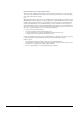
4.4 Clearing Paper Jams 4.4.7 Paper Jam — Paper Transfer Unit The paper jammed inside the paper transfer unit. After checking and clearing the jam in the paper transfer unit, also check the fuser unit and the primary transfer unit. Clear any paper jams in these components. 1 Open the front cover. Front Cover Figure 4-7 2 Grasp the handle at the end of the paper transfer unit and pull the unit out completely.
4.4 Clearing Paper Jams 3 Swing the green-colored lever to the right. Remove the jammed paper, if any, inside the cover. Figure 4-9 4 If there is jammed paper on the rubber belts (black) in the middle of the paper transfer unit, remove the paper.
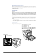
4.4 Clearing Paper Jams 5 If the paper is jammed in the fuser unit, open the fuser access cover by pressing the green-colored lock lever. The fuser unit is hot. Wait for a while until the fuser unit cools down. Caution Lock Lever (Green-colored) Fuser Access Cover Figure 4-11 6 Open the fuser top cover. Remove the jammed paper.
4.4 Clearing Paper Jams 7 If the paper is hard to remove, raise the sub-cover by grasping the clip marked as A on the rear side while removing the paper. Clip Sub-cover Figure 4-13 8 If the paper winds around the fuser roller, turn the wheel on the left-hand side of the fuser unit toward you. The jammed paper will be driven out. Remove the jammed paper. Wheel Figure 4-14 Rotate the wheel only in the direction illustrated in the diagram.
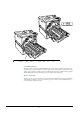
4.4 Clearing Paper Jams 9 Set the green lever on the front of the primary transfer unit clockwise to the position of six o’clock (usually this lever is in a position of four o’clock). This unlocks the primary transfer unit. Primary Transfer Unit Green Lever Figure 4-15 10 Grasp the handle at the end of the primary transfer unit and pull the unit out. Primary Transfer Unit Figure 4-16 11 Turn the wheel (with gear teeth) on the right-hand side of the primary transfer unit away from you.
4.4 Clearing Paper Jams 12 Push the primary transfer unit back in. To do this, lower the lock button close to the bottom end of the lever to unlock the lever. Set the lever (in the position of six o’clock) back to the original (four o’clock) position. See the figure below. Green Lever Lock Button Figure 4-18 13 Close the sub-cover, the top cover, and the access cover to the fuser unit, and push the fuser unit back into the printer. Figure 4-19 14 4.4.8 Close the front cover.
4.4 Clearing Paper Jams 1 Open the left cover for the face-up tray. Figure 4-20 2 Remove the jammed paper gently. If the paper is stuck under the roller, grasp the green-colored knob and rotate the roller in the direction indicated in the diagram so that the paper is driven out. Figure 4-21 If the paper does not go easily, refer to Section 4.4.7 Paper Jam — Paper Transfer Unit on page 4-17. 3 4.4.9 Close the left cover. Close the face-up tray.
Chapter 5 Maintenance 5 This chapter describes basic maintenance tasks you can perform on the printer.
5.1 Toner Container Replacement 5.1 Toner Container Replacement 5.1.1 Frequency of toner container replacement The life of the toner containers depends on the amount of toner required to accomplish your printing jobs. When 5 % coverage (a typical business document) of individual toner colors is assumed for A4 or letter size paper in landscape orientation: • • The black toner container lasts an average of 25,000 monochrome pages.
5.1 Toner Container Replacement 5.1.2 Understanding Messages Requesting Toner Container Replacement The printer displays messages for individual colors at two stages of toner usage. This message is automatically alternated with the other printer message (such as Ready): • • When the printer becomes low on toner, for example in the cyan container, the printer displays the message Toner low C, M, Y, K as the first caution. Note the replacement is not always necessary at this stage.
5.1 Toner Container Replacement 5.1.3 Replacing the Toner Container Note During toner container replacement, temporarily put storage media and computer supplies (such as floppy disks) away from around the toner container. This is to avoid damaging media by the magnetism of toner. This section explains how to replace the toner containers. When replacing the toner container of any color, always replace the waste toner box at the same time.
5.1 Toner Container Replacement 3 Put the old toner container in the plastic waste bag (contained in the toner kit) and discard it later according to the local code or regulations for waste disposal. Plastic Waste Bag Figure 5-3 4 5 Take the new toner container out of the toner kit. To loosen and redistribute the toner inside, hold the container and shake the container back and forth at least 5 times. New Toner Container Figure 5-4 6 Insert the new toner container all the way in.
5.2 Replacing the Waste Toner Box 5.2 Replacing the Waste Toner Box Replace the waste toner box each time you replace the toner container. A new waste toner box is included with the toner kit. The printer will not operate without replacing the waste toner box. 1 Pull the paper transfer unit all the way out. Slowly remove the waste toner box. Do not place the removed box upside down. Waste Toner Box Paper Transfer Unit Figure 5-6 2 The old waste toner box has a cap.
5.2 Replacing the Waste Toner Box 4 Insert the new waste toner box (contained in the toner kit) upright until it snaps into place. New Waste Toner Box Figure 5-9 Do not put the lid on the opening of a new waste toner box. This could cause damage to the printer. Caution After replacing the toner containers and the waste toner box, clean the paper transfer unit and the main charger unit. For instructions, see Section 5.3 Cleaning the Printer on page 5-8.
5.3 Cleaning the Printer 5.3 Cleaning the Printer As discussed earlier, the following parts must be cleaned each time the toner container and waste toner box are replaced: • • Paper transfer unit Main charger unit In addition to this, it is recommended that these parts are cleaned periodically at least once a month. 5.3.1 Cleaning the Paper Transfer Unit Print problems such as soiling of the reverse side of printed pages may occur if the paper transfer unit becomes dirty.
5.3 Cleaning the Printer 2 Grasp handle on the paper transfer unit and slowly pull it out. Paper Transfer Unit Figure 5-11 3 Clean the registration roller (metal) using the cleaning cloth. Be careful not to touch the transfer belt (brown) during cleaning as this may adversely affect print quality.
5.3 Cleaning the Printer 4 Clean the rubber belts (black) using the cleaning cloth. Rubber Belts Transfer Belt Figure 5-13 5 Push the paper transfer unit back in completely.
5.3 Cleaning the Printer 6 Close the front cover.
5.3 Cleaning the Printer 5.3.2 Cleaning the Main Charger Unit The main charger unit needs to be cleaned periodically as it gets contaminated with dioxide after a long usage. The main charger is comprised of two main parts — the wire and the grid — which should be cleaned separately as instructed below. To clean the main charger unit, proceed as follows: 1 2 Open the front cover. First we clean the main charger wire. Grasp the tab of the cleaning knob (green-colored).
5.3 Cleaning the Printer 4 Attach the grid cleaner to the printer with the pad facing up. Grid Cleaner Figure 5-18 5 While pushing the main charger unit lock lever upward as shown in Figure 5-19, slightly lift the main charger unit, and gently pull the gray-colored main charger handle out and push it back in. Repeat this 2 to 3 times. These movements clean the grid. Lock Lever Main Charger Unit Figure 5-19 6 After cleaning is finished, remove the grid cleaner from the printer and discard it.
Appendix A Options Your printer can be installed with various options indicated in this appendix. You can select the options that will satisfy your printing requirements. For availability of the options, consult your Kyocera Mita dealer. Caution CA-31B is a caster kit to prevent the FS-C8008 printer from tipping over because of weight in the printer and the upper paper drawers.
A.1 Options A.1 Options The FS-C8008 series printers have the following options available. For instructions on installing individual options, refer to the documentation included with the option. Some options are explained in the following sections.
Expansion Memory Modules A.2 Expansion Memory Modules To expand the printer memory for more complex print jobs and faster print speed, you can plug in optional memory modules (dual in line memory modules) in two memory slots provided on the printer main controller board. You can select additional memory modules from 32, 64, 128, or 256 MB (the maximum memory size is 640 MB, including the base 128 MB memory). Note Only an authorized Kyocera Mita dealer should install the expansion memory.
A.2 Expansion Memory Modules A.2.1 Installing the Memory Modules 1 2 Power off the printer and unplug the printer power cord. Unscrew two screws at the back of the main controller board. Figure A-3 3 Pull out the main controller board gently.
Installing the Memory Modules 4 Push out the clamps on both ends of the memory socket on the main controller board. Clamps Figure A-5 5 Remove the memory module from its package. Aligning the cutouts of the memory module with the matching keys of the socket, carefully plug the memory module into the memory socket until it clicks in place. Cutouts Figure A-6 6 Push down the two socket clamps to secure the memory modules.
A.2 Expansion Memory Modules Removing a Memory Module To remove a memory module, remove the main controller board, then carefully push out the two socket clamps. Ease the memory module out of the socket to remove. Testing the expanded memory To verify that the memory modules are working properly, test them by printing a status page. To print a status page: 1 Make sure the printer is switched off. Plug in the printer power cord into an AC outlet and power on the printer.
Memory Card A.3 General Description of Options A.3.1 Memory Card The printer is equipped with a slot for a memory card with the maximum size of 256 MB. A memory card is useful for storing fonts, macros, and overlays. You can use the IC Link for Windows utility to download fonts, etc., to a flash memory card. This software is included in the CD-ROM supplied with the printer.
A.3 General Description of Options A.3.2 PF-30A Paper Feeder The PF-30A paper feeder has two paper cassettes allowing a large number of sheets of paper to be fed continuously for printing. The paper cassette can hold up to approximately 500 sheets of ISO A3, ISO A4, ISO A5, JIS B4, JIS B5, ledger, letter, and legal size (80 g/m²) paper. This feeder is attached at the bottom of the printer as shown below.
PD-800 Duplex Unit A.3.3 PD-800 Duplex Unit This duplex unit is provided as a standard accessory for the FS-C8008DN printer. The PD-800 is similar to the PF-30A paper feeder but has a duplexer (required for printing on both sides of a sheet) in place of the first paper cassette. Printing on both sides can be performed using ISO A3, ISO A4, ISO A5, JIS B4, JIS B5, ledger, letter, and legal sized paper.
A.3 General Description of Options A.3.5 ST-30 Bulk Stacker This bulk stacker can hold up to 3,000 copies for a continuous, voluminous output. It incorporates the jog feature to avoid loss or mishandling of printouts by staggering and dividing the stacked printed sheets. The bulk stacker is attached to the left side of the printer as shown below. Use the supplied dedicated bracket to attach the bulk stacker to the printer.
DF-31 Document Finisher A.3.6 DF-31 Document Finisher This multipurpose device is used for organizing printouts. The device can staple printed sheets by electronic means and provides three output trays for stacking printed sheets after dividing and staggering them according to print jobs. The document finisher is attached to the left side of the printer as shown below. Use the supplied dedicated bracket to attach the document finisher to the printer, Figure A-13 A.3.
A.3 General Description of Options A.3.8 Hard Disk The hard disk is used for saving print data. This is advantageous when printing multiple sets of copies, as high-speed printing is possible using the electronic sorting function. The hard disk is further required in order to use the e-MPS function. You can use the KM-NET Printer Disk Manager utility to keep track of the stored data. This software is included in the CD-ROM supplied with the printer.
IB-20/IB-21E/IB-22 Network Interface Cards A.3.9 IB-20/IB-21E/IB-22 Network Interface Cards Along with the standard for the network interface on the printer, the network interface card supports TCP/IP, IPX/SPX, NetBEUI and EtherTalk protocols, so that the printer can be used on network environments including Windows, Macintosh, UNIX, NetWare, etc. Install the network interface card in the OPT slot located on the lower right side of the printer rear as shown below.
Appendix B Computer Interface This appendix explains the signals used in the printer's parallel, USB, and serial (option) interfaces. It also lists pin assignments, signal functions, timings, connector specifications, and voltage levels.
B.1 Parallel Interface B.1 Parallel Interface B.1.1 Communication Modes The printer provides high-speed data transmission on a parallel interface. You can select the parallel interface communication mode from the operation panel. To change communication mode, see Chapter 3 Using the Operator Panel, section 3.5.1 Changing Parallel Interface Mode on page 3-34. Use a parallel interface cable that complies with the IEEE 1284 standard.
B.1 Parallel Interface B.1.2 Interface Signals Table shows the connector pins and corresponding input and output signals of the parallel interface. Explanation of each signal is also given in the table. The description in [ ] indicates signal names in Auto mode and Nibble (high) mode (IEEE 1284-compliant). In Auto and Nibble modes, these signals are bidirectional.
B.1 Parallel Interface Pin In or out Signal Description 30 — Ground return 31 In — [nInit] Ignored 32 Out Error† [nFault] When the high-speed parallel line control is on, this line returns an error status.†† 33 — — Not used 34 — — Not used 35 Out Power Ready This signal goes high when the printer is powered on. 36 In Select In [nSelect In] When this line is high, IEEE1284 mode is enabled. Table B-2 † †† Indicates signals that are low active.
B.2 USB Interface B.2 USB Interface This printer supports the Full-Speed USB 2.0. USB (Universal Serial Bus) interface specifications and interface signals are as follows. B.2.1 Specifications Basic specification Complies with the Full-Speed USB 2.0. Connectors Printer: B-type receptacle (female) with upstream port Cable: B-type plug (male) Cable Use a shielded cable that complies with USB 2.0 and not longer than 5 meters (16 feet). Transfer Mode Full speed (max.
B.3 Serial Interface (Option) B.3 Serial Interface (Option) Installing the optional serial interface board kit (IB-11) in the printer enables connection to a computer with an RS-232C standard serial interface. B.3.1 Interface Signals Table B-4 below shows the pins and corresponding input and output signals of the RS-232C interface connector. Pin In or out Signal Description 1 — FG Frame Ground. This pin is connected directly to the printer frame. 2 Out TXD Transmit Data.
B.4 RS-232C Protocol B.4 RS-232C Protocol B.4.1 Parameters of the RS-232C Protocol A protocol is a set of rules followed by various devices to send or receive data. The parameters of the RS-232C protocol are stored in the battery-powered memory of the printer.
B.4 RS-232C Protocol H4: Parity Parameter value Meaning 0 None 1 Odd 2 Even 3 Ignored The factory setting is 0 (none). H5: Protocol logic Parameter value Meaning 0 Combination of DTR (positive logic) and XON/XOFF 1 DTR (positive logic) 2 DTR ( negative logic) 3 XON/XOFF 4 ETX/ACK The factory setting is 0. H6: Buffer nearly-full threshold A percentage value from 0 to 99. The factory setting is 90. H7: Buffer nearly-empty threshold A percentage value from 0 to 99.
B.5 RS-232C Cable Connection B.5 RS-232C Cable Connection B.5.1 Preparing an RS-232C Cable After you procure an RS-232C cable, check its wiring against the pin assignments shown in page section B.1.2 Interface Signals on page B-3. If you have an IBM communications adapter cable type 1502067, use the procedure below to solder the wiring at the end (printer side) of the cable: 1 Unscrew the plastic cover at the end (printer side) of the cable.
B.5 RS-232C Cable Connection If you are not sure about the printer’s current parameter settings, reset them to the values shown above (i.e., baud rate = 9600 bps, etc.). You can perform parameter settings from the operation panel. See Chapter 3 Using the Operator Panel, section 3.5.2 Changing Serial Interface Parameters on page 3-35. 6 On the computer, set the same parameters as that of the printer. Most computers allow you to do this by DIP switch settings that should be made before power is turned on.
B.5 RS-232C Cable Connection With Windows 95/98/Me, make settings as follows: 1 Click on the Start button in the Windows 95/98/Me task bar and align the cursor with Settings, then click on Control Panel from among the items displayed. 2 3 The Control Panel window opens. Double click on System. System Properties window opens. Click on the Device Manager tab, then double click on Ports (COM & LPT). Figure B-3 4 5 Double click on Communications Port.
B.5 RS-232C Cable Connection In DOS, enter the following commands: C:\>MODE COM1:96,N,8,1,P C:\>MODE LPT1:=COM1 To test the interface, enter the following: CTRL P C:\>DIR CTRL P The software settings made using the above procedures are temporary. On most computers, permanent settings must be made with DIP switches.
Appendix C Technical Specifications The technical specification may be changed for improvement purpose.
C.1 Printer Specification C.1 Printer Specification Item Specification Printing method Electrophotographic four color (CMYK) printing using laser diode. Printing speed See section C.2 Printing Speeds on page C-4.
Printer Specification Item Specification Output tray capacities Face-down tray 500 sheets (80 g/m²) Operating environment Power supply Face-up tray 150 sheets (80 g/m²) Temperature 10 to 32.5 °C (50 to 90.5 °F) Relative humidity 15 to 80 % Optimum conditions 23 °C (73 °F), 60 % (relative humidity) Altitude 2,000 m (6,500 feet) maximum Illumination 1,500 lux or less U.S.A. and Canada 120 V, 60 Hz, 11.5 A max Europe, Asia, and other countries 220 to 240 V, 50 or 60 Hz, 5.8 A max.
C.2 Printing Speeds C.
Index A Audible alarm how to set 3-95 Auto-continue changing recovery time 3-97 how to set 3-96 C Carriage return how to select 3-57 Cleaning belts 5-10 main charger unit 5-12 paper transfer unit 5-8 registrtion roller 5-9 using the grid cleaning tool 5-12 Color control calibration 3-100 selecting monochrome or color printing 3-85 Counters reading the life counters 3-86 reading the total printed pages 3-86 toner, how to reset 3-87 D Data dump receiving data for damping 3-92 Document finisher option, diagr
Paper Type 3-5 Ready, Data, Attention 3-5 J Job retention functions tabled 3-20 private job, how to use 3-24 proof-and-hold, how to use 3-23 quick copy, how to use 3-21 Job storage functions 3-21 K Keys arrow keys 3-7 basic operation 3-6 Cancel 3-6 Enter 3-7 Go 3-6 Menu 3-7 KPDL3 as software feature 1-4 L Label required composition 2-12 requirements 2-13 Linefeed how to select 3-56 M Main charger unit location 1-7 Memory expanding memory A-3 installing memory modules A-4 on the status page 3-19 Memory c
special paper 2-11 specifications, tabled 2-2 standard sizes 2-4 transparencies 2-12 Paper cassette as hardware feature 1-3 clearing paper jam 4-14 diagram 1-5 selecting the paper feed source 3-74 setting paper type 3-73 Paper feeder diagrammed A-8 Paper jam general considerations 4-13 messages and corrective actions, diagrammed 414 possible locations, diagrammed 4-12 Paper transfer unit clearing paper jam 4-17 location and function 1-8 Paper type creating custom 3-77 custom paper type, fuser mode 3-79 how
Kyocera Mita Corporation 2-28, 1-Chome, Tamatsukuri Chuo-ku, Osaka, 540-8585 Japan 2002 by KYOCERA MITA CORPORATION All rights reserved. Revision 1.0., 2002.