Xerox Document Services Platform DocuTech 65/DocuPrint 65 Operator Guide 701P36056 DocuSP version 2.0.
Xerox Corporation Global Knowledge and Document Services 800 Phillips Road Building 845-17S Webster, New York 14580 USA © 2001 by Xerox Corporation. All rights reserved Copyright protection claimed includes all forms and matters of copyrighted material and information now allowed by statutory or judicial law or hereinafter granted including without limitation, material generated from the software programs that are displayed on the screen such as styles, templates, icons, screen displays, looks, and so on.
Table of contents Introduction . . . . . . . . . . . . . . . . . . . . . . . . . . . . . . . . . . . . . . . . . . . . . i About this guide . . . . . . . . . . . . . . . . . . . . . . . . . . . . . . . . . . . . . . . . . . . . . .i Powering down the system . . . . . . . . . . . . . . . . . . . . . . . . . . . . . . . .i Contents . . . . . . . . . . . . . . . . . . . . . . . . . . . . . . . . . . . . . . . . . . . . . ii Requirements . . . . . . . . . . . . . . . . . . . . . . . . . . . . . . . . . . . . .
Table of contents Operator Guide Finisher . . . . . . . . . . . . . . . . . . . . . . . . . . . . . . . . . . . . . . . . . . . Unloading the Stacker during printing . . . . . . . . . . . . . . . . . . . Peripheral hardware components . . . . . . . . . . . . . . . . . . . . . . . Controller software . . . . . . . . . . . . . . . . . . . . . . . . . . . . . . . . . . . . . . . Modems . . . . . . . . . . . . . . . . . . . . . . . . . . . . . . . . . . . . . . . . . . . . . . . .
Introduction The DocuTech 65/DocuPrint 65 Operator Guide is one of a number of publications which make up the Xerox Document Services Platform Series. About this guide This guide is intended for Xerox DocuTech65/DocuPrint 65 operators whose job consists of the routine operation of this printing system: operating each of the system components, running print jobs, solving simple system problems, and performing basic maintenance tasks, such as replenishing printer supplies.
Introduction Operator Guide Contents This section lists the contents of this guide. ii • “Introduction” gives a basic overview of the Operator Guide and its contents. It also contains information on requirements and certifications required by USA and Canadian regulations. • “Safety Notes” explains the various symbols, Cautions, and Warnings pertaining to the safe use and operation of the DocuTech 65/DocuPrint 65 systems.
Operator Guide Introduction Requirements Telephone requirements USA FCC requirements: • The FCC has established rules that permit the device to be directly connected to the telephone network. Standardized jacks are used for these connections. This equipment should not be used on party lines or coin lines. • If this device is malfunctioning, it may also be causing harm to the telephone network; this device should be disconnected until repair has been made.
Introduction Operator Guide Canadian industry requirements Notice: The Canadian Industry Canada label identifies certified equipment. This certification means that the equipment meets certain telecommunications network protective, operational and safety requirements. The Department does not guarantee the equipment will operate to the user’s satisfaction.
Operator Guide Introduction Electromagnetic comparability United States This equipment has been tested and found to comply with the limits for a Class A digital device, pursuant to part 15 of the FCC Rules. These limits are designed to provide reasonable protection against harmful interference when the equipment is operated in a commercial environment.
Introduction -vi Operator Guide DocuTech 65/DocuPrint 65
Safety notes Please read the following instructions carefully before planning your install and/or operating the DocuTech 65/DocuPrint 65. Refer to them as needed to ensure the safe installation and operation of your equipment. The safety testing and performance of this product have been verified using Xerox materials only Your Xerox DocuTech 65/DocuPrint 65 and its supplies have been designed and tested to meet strict safety requirements.
Safety notes Operator Guide WARNING Warnings indicate possible serious personal injury if you do not strictly follow the practice, procedure, condition, or statement that follows the WARNING. CAUTION Cautions indicate that possible system damage or data loss will occur if you do not carefully follow the practice, procedure, condition or statement that follows the CAUTION.
Operator Guide Safety notes WARNING This is a Class A product. In a domestic environment this product may cause radio interference in which case the user may be required to take adequate measures. WARNING This system is certified manufactured and tested in compliance with strict safety and radio frequency interference regulations. Any unauthorized alteration which includes the addition of new functions or the connection of external devices may impact this certification.
Safety notes Operator Guide Electricity at Work Regulation - UK The Electricity at Work Regulation applies only to England and Wales. The Regulation The Electricity at Work Regulation 1989 came into force in England and Wales on the 1 April 1990. This 1989 Regulation places a duty on all employers and self-employed persons to ensure the electrical systems in their premises are constructed, maintained and operated in such a manner as to prevent, so far as reasonably practical, danger.
Operator Guide Safety notes Check your understanding Please review the questions and answers that follow to ensure that you understand the Electricity at Work Regulation in England and Wales. Question Answer Question Answer What is the Electricity at Work Regulation? The Electricity at Work Regulation 1989 came into force in England and Wales on the 1 April 1990.
Safety notes Operator Guide Question Answer Does the Xerox equipment in my premises comply with the Electricity at Work Regulations? All employers and self-employed persons must ensure that the electrical systems in their premises are safe. This will include ensuring Xerox equipment in such premises is safe. Xerox Europe’s Product Safety function has prepared a guide which contains a list of tests which may be completed by your Xerox Europe Customer Service Organization.
Operator Guide Safety notes Electrical safety Attention to the following requirements ensures the safe operation of your equipment. Printer USA/Canada Europe The printer requires a 115V AC outlet, dedicated 20 Amp, 3-wire circuit. The printer requires a 220-240V outlet, dedicated 13 Amp or 10 Amp circuit. The equipment must be connected to a grounded mains outlet. CAUTION Ensure that the power connection for your printer satisfies these requirements.
Safety notes Operator Guide Controller USA/Canada Europe The controller requires a dedicated 115V AC 20 Amp grounded receptacle. The controller requires a 220-240V, 13 or 10 Amp grounded receptacle. CAUTION Follow all safety cautions, warnings, and instructions marked on the controller. xiv • Ensure that the voltages and frequency rating of the power receptacle match the electrical rating label on the equipment. • Do not make electrical or mechanical modifications to the equipment.
Operator Guide Safety notes Printer power on/off indicator A power-on/power-off indicator shows the state of the power for the printer. This indicator is located on the top front of the printer and has a rectangular shape. This indicator glows green when printer power is on and emits no light, is colorless, when the printer power is off.
Safety notes Operator Guide Printer or controller - emergency power off If any of the following conditions occur, turn off the equipment immediately and disconnect the power cable from the electrical outlet. Contact an authorized Xerox Service Representative to correct the problem: • The equipment emits unusual odors, or makes unusual noises. • The power cable is damaged or frayed. • A wall panel circuit breaker, fuse, or other safety device has been tripped. • Liquid is spilled into the equipment.
Operator Guide Safety notes Printer - laser safety CAUTION The use of controls, adjustments or performance of procedures other than those specified in this guide may result in hazardous light exposure. With specific regard to lasers, the equipment complies with laser product performance standards set by governmental, national, and international agencies as a Class 1 Laser Product. It does not emit hazardous light, as the beam is totally enclosed during all phases of customer operation and maintenance.
Safety notes Operator Guide Printer - operational safety Safety Quality Standards The equipment is manufactured under a BS5750 Quality system accepted by the British Standards Institution. Other National Standards The Xerox DocuTech 65/DocuPrint 65 is also certified in compliance with applicable standards by various national bodies.
Operator Guide Safety notes Your Xerox DocuTech 65/DocuPrint 65 printer is certified, manufactured, and tested in compliance with strict safety and radio frequency interference regulations. Any unauthorized alteration that includes the addition of new functions or the connection of external devices may invalidate this certification. Please contact your local Xerox representative or the Xerox Welcome Center for a list of approved accessories.
Safety notes -xx Operator Guide DocuTech 65/DocuPrint 65
1. Product overview This chapter will introduce the controller and overview the capabilities of the printer. Hardware components The main DocuTech 65/DocuPrint 65 components are: • Controller (CPU with external modem, CD-ROM drive, diskette drive, monitor, keyboard, and mouse) • Printer (with internal modem) Peripheral components may include: • External SCSI Hard Drive • External Tape Drive Peripheral components may be contained within a special accessory shelf that is attached to the printer.
Product overview Operator Guide Controller components The main controller components are shown in Figure 1-1. Figure 1-1.
Operator Guide Product overview Printer components The main components of the printer are shown in Figure 1-2. Figure 1-2. Printer components Tray 5, Bypass Tray for odd size or special stock Top Tray Stacker Finisher for stapled sets Tray 6, High Capacity Feeder with 3100 sheet capacity for main stock Paper Trays 1-4 hold many types of stock The following information sources are provided to assist you: DocuTech 65/DocuPrint 65 • Power-on/power-off indicator is on the top front of the printer.
Product overview Operator Guide Paper trays (trays 1-4) Paper Trays 1-4 are shown below in Figure 1-3. Figure 1-3. Trays 1-4 Trays 1 through 4 The Paper Trays hold up to 500 sheets of 20 lb (75 gsm) stock each. You can adjust the trays to hold many sizes of paper, from 5.5 x 8.5 inches (140 x 216 mm) up to 11 x 17 inches (279 x 432 mm or A3). To handle 12 x 18 inch paper, a tray must be specially set up.
Operator Guide Product overview Bypass tray (tray 5) The Bypass Tray (Tray 5) is an additional paper tray designed for quick and easy loading of both standard and non-standard paper. It can physically extend to accommodate different stock sizes and orientations. You can load a maximum of 50 sheets of standard weight 20 pound (75 gsm) stock. If using a heavier stock, fill the tray only to the maximum-fill line. The Bypass Tray has a capability of 4 to 12 inches (102 to 305 mm); 5.
Product overview Operator Guide High Capacity feeder (tray 6) The High Capacity Feeder (Tray 6) is located under the Bypass Tray and saves you from having to load the other individual paper trays with 8.5 x 11 inch (216 x 279 mm) paper often. You can load 3100 sheets of 20 pound (75 gsm) 8.5 x 11 inch (216 x 279 mm) Long Edge Feed (LEF) paper. The High Capacity Feeder can feed only 8.5 x 11 inch (216 x 279 mm) or A4 LEF paper and cannot be adjusted to hold any other sizes or orientations. Figure 1-5.
Operator Guide Product overview Tray guides and loading paper Do not open a tray that is in use, a paper jam may result. Instead, before opening a tray, disable the tray in the Printer Manager. After loading the paper, enable the tray in the Printer Manager. Performance capabilities Performance capabilities for various paper types loaded in specific trays are given in the chapter, Paper and other stock. Loading paper in Trays 1-4 1. Pull out the paper tray.
Product overview Operator Guide NOTE: For information about how to load specific types of paper or other stock, refer to the chapter, Paper and other stock. Loading paper in the Bypass Tray (Tray 5) Insert paper as shown. The Bypass Tray extends to accommodate paper that is physically longer than the tray. Simply pull out the extension bar. Do not load paper above the maximum fill line. Loading paper in the High Capacity Feeder (Tray 6) To load paper, open the cover and wait for the tray to lower.
Operator Guide Product overview Changing the Tray 6 settings You can set Tray 6 to hold either A4 or 8.5 x 11 inch paper. An example of changing the tray setting from 8.5 x 11 inches to A4 is shown in Figure 1-8. Figure 1-8. Changing the guides from 8.5 x 11 inches to A4 Rear Guide Starting with the Rear Guide, you will adjust the guide to the A4 position. Perform the following: 1. Slide the black latch down to release the guide. 2. Move the guide out, over, and in, into the A4 position. 3.
Product overview Rear Guide Operator Guide Starting with the Rear Guide, you will adjust the guide to the 8.5 x 11 inch position. Perform the following: 1. Slide the black latch down to release the guide. 2. Move the guide out, over, and into the 8.5 x 11 inch position. 3. Slide the latch up to lock the guide. Front Guide Repeat the procedure for the front guide NOTE: Be sure to reprogram the tray in the Printer Manager to reflect the changed size.
Operator Guide Product overview Finisher The Finisher consists of the Top Tray and the Stacker Tray, as shown below in Figure 1-9. Figure 1-9. Finisher components Top Tray Finisher button Stapler is within the finisher Press the Finisher Button to unload the Stacker Tray during a print run Top Tray The Top Tray holds sheets that are purged from the system or up to 250 prints. Stacker Tray The Stacker Tray is the output tray for all other jobs.
Product overview Operator Guide Stapling Removing any of the output while the printer is running may produce finished sets that are incorrectly stapled. To ensure that the stapling of thin sets is satisfactory, the printer performs the following actions. Finishers before the end of 1998 After 30 finished sets of 15 sheets, the printer: 1. cycles down 2. may raise a message to empty the Finisher (Stacker Tray) 3. waits briefly, whether the sets are removed or not 4. cycles up and resumes printing.
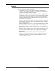
Operator Guide Product overview Staple placement For information about the limitations of portrait and landscape staple placement, refer to the Staple Placement table below. Table 1-1.
Product overview Operator Guide Peripheral hardware components You may have peripheral components such as an External SCSI Hard Drive and an External Tape Drive on a special accessory shelf as shown in Figure 1-10. Figure 1-10.
Operator Guide Product overview Controller software The controller runs the DocuSP Print Services software. This software gives the printer operator the ability to manage the jobs and the printer. For detailed information on how to use the DocuSP Print Services software, refer to the DocuSP on-line Help. Modems The controller has an external modem that is on or off according to the site requirements for this modem or as needed by Xerox service.
Product overview 1-16 Operator Guide DocuTech 65/DocuPrint 65
2. Maintenance Your Xerox DocuTech 65/DocuPrint 65 system is designed to maximize printer performance. This includes using a short paper path in order to reduce jams, and Customer Replaceable Units (CRUs) in order to avoid extended periods of downtime.
Maintenance Operator Guide Controller power-on procedure The controller power-on button and the Light Emitting Diode (LED) are shown in Figure 2-1. The LED glows green when the controller power is on. Figure 2-1. Controller power-on button and LED LED Power On Button To power on the controller: 1. Switch on the power for each of the connected peripherals. 2. Switch on the monitor. 3. Press the controller “On” button. 4. Confirm that the controller LED light is on.
Operator Guide Maintenance Printer power-on procedure When the printer is on, the power-on/power-off indicator glows green. The printer must be switched on by pressing a switch on the printer. The printer cannot be powered on from the DocuSP Print Services interface that runs on the controller. The printer power switch is shown in Figure 2-2.
Maintenance Operator Guide Power-off procedures You can power off only the printer and allow the controller to keep on processing jobs, or you can power off both the printer and the controller. Printer power-off When the printer power is off, the power-on/power-off indicator does not emit light, it is colorless. Under normal operating conditions the printer should be powered off using the DocuSP Print Services on the controller, rather than by pressing the printer on/off switch.
Operator Guide Maintenance Figure 2-3. Printer power-off Printer Power-Off Using The Red Button A red button, located inside the printer, provides a less gentle method for powering off the printer. This power-off procedure immediately cuts power to the printer in an uncontrolled manner without confirmation or delay. Any jobs in the queue will be immediately lost without confirmation.
Maintenance Operator Guide Figure 2-4. Printer power-off, red button RED BUTTON After the Red Button is used, the printer will take longer to reboot.
Operator Guide Maintenance Controller power-off The controller power-off button is shown in Figure 2-5. The LED light is out when the controller power is off. To power off the controller: 1. Notify the job submitters that the controller is about to be powered off. 2. Back up system files and data. CAUTION Before switching off the controller, exit any applications that are running and shut down the DocuSP Print Services using the Shutdown option so that you do not lose any data. 3.
Maintenance Operator Guide CAUTION When the power on/standby switch is in stand-by and the AC power cord remains connected to a power receptacle, AC voltage is present in the power supply. 10. If the equipment will be serviced or moved, disconnect the AC power cord from the AC receptacle. Emergency power-off procedures An emergency power-off procedure may be used when the power must be switched off immediately. CAUTION The controller emergency power off procedure may corrupt the DocuSP software.
Operator Guide Maintenance Printer faults Occasionally, a fault will occur at the printer that may prevent you from using the printer, such as: • Out of Paper • Low Dry Ink • Module/Cartridge end of life • Paper Jam NOTE: For detailed information on the Customer Replaceable Units, refer to the DocuTech 65/DocuPrint 65 Operator Guide and the DocuSP Help. Clearing printer faults Instructions for clearing faults will be displayed on the controller. Simply follow the instructions.
Maintenance Operator Guide Figure 2-6. Jam clearance areas Area 1 Sheets may be left in this area when jams occur. Area 2 The Lift Handle: The printer is programmed to circulate paper to this area in the event of a jam. Raise the handle to clear this area. Do not move the handle to the left. Ensure that the handle is fully locked by lowering it before closing the Front Door or the handle may be blocked or damaged. Area 3 The Fuser area: This area includes areas 3b, 3c, and 3d.
Operator Guide Maintenance Area 5 To access Areas 5, 5a, and 5b you need to open the Finisher area. The Finisher area is shown in Figure 2-7. Lift and pull Handle 5 to get access to paper in areas 5a and 5b. Figure 2-7.
Maintenance Operator Guide Area 7 To access Area 7, you need to open the High Capacity Feeder (Tray 6) and Bypass Tray (Tray 5) areas. The High Capacity Feeder and the Bypass Tray are shown in Figure 2-8. Lift and pull the top cover of the Bypass Tray to access area 7a. Figure 2-8.
Operator Guide Maintenance Replaceable units and supplies The printer is designed to allow the customer to change major components such as the Xerographic Module, the Fuser Module, the Dry Ink Cartridge (Toner), or the Feed Roll Cartridges without having to initiate a service call. These and other replaceable supplies are shown in Figure 2-9. Figure 2-9. Location of CRUs and supplies 1. Ink Cartridge (Toner Cartridge) - a consumable supply 2. Fuser Module - a Customer Replaceable Unit (CRU) 3.
Maintenance Operator Guide Replaceable items The following components are replaceable: • The Xerographic Module • The Fuser Module • The Paper Feed Roll Cartridges • Dry Ink (Toner) Cartridge • Staple Cartridge • Developer Collector Bottle If a replacable item must be changed, a message will appear on the controller. To replace these units, simply follow the instructions provided with each replacement box. Also, use the box and prepaid return label to return the old unit to Xerox.
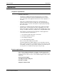
Operator Guide Maintenance Life expectancies and part numbers for CRUs and supplies are listed in Table 2-2. Table 2-2. Life expectancy for CRUs and consumable supplies Item Description and Life Expectancy Part Number Fuser CRU 400K imps.hard stop, 310K average USA and Canada: Note: DocuTech 65/DocuPrint 65 ignores the hard stop but displays a CRU message.
Maintenance Operator Guide When placing orders, give the representative the following information: • Your Xerox customer number • Your system model name and number • A description of the item • The quantity of the item Dry Ink (Toner) usage and “Dry Ink Low” message Dry ink (toner) usage is related to the amount of area that needs to be printed (covered).
3. Paper and other stock Your printer can process a variety of paper and other stock to accommodate your needs. This chapter contains information about the stock you can use in the printer and how you can expect it to perform. Stapling guidelines and the correct loading of special stocks is also discussed as well as stock storage requirements. Performance information The following tables list the printer performance expectations for both onesided and two-sided printing, on paper and on other stock.
Paper and other stock Operator Guide Paper handling guidelines Paper handling and/or image quality performance degradation might occur in the following situations: • Lower quality paper • Extreme hot and humid or cold and dry environments The size limitation for duplex printing is shown in Figure 3-1. Figure 3-1. Size requirement for duplex printing This edge must be between 6.7 to 18 inches (170 to 457 mm) to be printed on both sides (duplexed).
Operator Guide Paper and other stock Tray capabilities: The trays are shown in Figure 3-2. Figure 3-2. Tray capabilities Tray 5 Tray 6 Trays 1 - 4 Tray 5 The Bypass Tray has a capability of 4 to 12 inches (102 to 305 mm); 5.83 to 18 inches (148 to 457 mm). Tray 6 The High Capacity Tray has a capability of only 8.5 x 11 inch (216 to 279 mm) or A4 long-edge feed (LEF), between 16-32 lb (75-120 gsm). Trays 1-4 Have a capability of 8 to 17 inches (203 to 432 mm); 5.25 to 11 inches (133 to 279 mm).
Paper and other stock Operator Guide General stapling guidelines To ensure that stapling of thin sets is satisfactory, finishers made before the end of 1998 will cycle down and wait briefly after producing 30 sets of 15 sheets to give you an opportunity to proof the job. You are not required to empty the Stacker in order to resume printing. For Finishers made after the end of 1998, a similar process takes place except that you are required to empty the Stacker in order to resume printing.
Operator Guide Paper and other stock Performance tables In the printer performance tables, various symbols and characters are used to convey information. Symbols The following symbols in the “Rating” column of a table represent the expected paper handling and image quality performance in typical operating environments. l = Best performance o = Good performance o = Fair - Good performance x = Not recommended. Exceeds design specifications. Unacceptable performance is likely.
Paper and other stock Operator Guide NOTE: For all trays, the fusing quality and “fix level” for images on 65 lb. cover stock, Vellum Bristol papers, and other textured-surface stock will be degraded; therefore, this stock is not recommended for imaging use. NOTE: Long Edge Feed (LEF) and Short Edge Feed (SEF) indicate the orientation of the sheet in a Paper Tray and which edge of the paper will be fed into the printer first.
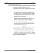
Operator Guide Paper and other stock The printer performance using standard 80 gsm paper in common Xerox Europe sizes is shown in Table 3-3. Table 3-3. Printer performance for standard paper 80 gsm (Xerox Europe) Rating Size Feed Tray 1-4 SEF Tray 5 Tray 6 Note l l x LEF l l l SEF o o x LEF o o x SEF o o x LEF x o x a SEF o o x b SEF x o x a, b SEF l l x LEF x o x SEF l l x b SEF x o x b 215 x 330 mm (8.5 x 13 in.) SEF o o x 220 x 330 mm (8.
Paper and other stock Operator Guide The printer performance for non-standard paper and other types of stock is shown in Table 3-4. You may run the stock if you follow the guidelines in the table and if the dimensions of the stock are within the size limits previously discussed for standard paper. Table 3-4.
Operator Guide Paper and other stock The printer performance for new and recycled 8.5 x 11 inches (216 to 279 mm) or A4 paper for various weights is shown in Table 3-5. Table 3-5. Printer performance for new and recycled plain paper Paper Weight Throughput Material 8.5 x 11 in.
Paper and other stock Operator Guide Table 3-6. Recommendations for loading special stock Stock Type Reinforced Mylar edge Common Use Ringed binders 3 or 4 holes Recommendation • Load reinforced edge on the right in Trays 1-4. • Load reinforced edge on the left in Trays 5-6. • Use long-edge feed only. Card stock Covers, signs • Feed from the Bypass Tray for best results. Tabs Separators within a document • Use the Tab Tray insert. • Feed from trays 2, 3, and 4 only.
Operator Guide Paper and other stock Table 3-6. Recommendations for loading special stock Stock Type GBC stock (Sameceda) DocuTech 65/DocuPrint 65 Common Use Plastic comb or strap binding via slotted holes or rectangles at frequent intervals along the long edge (the bind edge) Recommendation • Load with slotted holes inboard; for example, load SEF when the holes are down the long edge.
Paper and other stock Operator Guide Recommendations for handling, loading, and storing paper Give your paper the proper handling, loading, and storage. Loading and handling Before loading paper, unwrap the paper from the moisture resistant wrappings, discard the wrapper and insert the paper in the tray. If it is special stock such as punched paper follow the orientation label on the tray or the recommendations in Tables 3-4 and 3-6 of this chapter.
4. Problem solving This chapter will assist you in avoiding problems and solving those that may occur. It also provides information on how to contact the Welcome Center. Avoiding the problems A variety of situations can affect the quality of the printer output. For optimal performance, follow these guidelines: DocuTech 65/DocuPrint 65 • Do not locate the printer in direct sunlight or near a heat source such as a radiator. • Avoid sudden changes in the environment surrounding the printer.
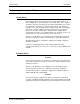
Problem solving Operator Guide Solving the problems Recommendations for solving some common problems are listed in Table 4-1. Table 4-1. Troubleshooting tips Problem Symptom Controller/ Printer The printer is not receiving jobs from the controller or will not go on when switched on. • Check to see if the cable that connects the controller to the printer is plugged in correctly. Each end of the cable has a plug that is keyed for correct fit.
Operator Guide Problem solving Table 4-1. Troubleshooting tips Problem Stock handling Stock handling DocuTech 65/DocuPrint 65 Symptom There are repeated stock jams or misfeeds in Tray 5. There are repeated shut downs from jams in Area 3 or the prints show an unexpected image shift when feeding from Tray 5. Recommendation • Ensure that the correct stock size is displayed on the Print Services, Printer Manager window. • Remove the stock and reload the tray.
Problem solving Operator Guide Table 4-1. Troubleshooting tips Problem Stock handling Stock handling Symptom There are jams inside the printer. The stock curls up or down. Recommendation • Check the paper path for obstruction. • Make sure that the Area 2 Lever is in the correct position (down). • Flip the stock over in the tray. • Check the tray Edge Guides to see if they are against the edges of the stock.
Operator Guide Problem solving Calling the Welcome Center If you are experiencing difficulty with your printer, check the troubleshooting tips shown in Table 4-1. Attempt to solve the problem before contacting the Welcome Center. You might be able to resolve the situation quickly. If the difficulty persists, contact the Xerox Welcome Center. The Welcome Center telephone number and other relevant information are conveniently located on the Diagnostics window.
Problem solving 4-6 Operator Guide DocuTech 65/DocuPrint 65