Xerox Document Services Platform DocuTech/DocuPrint 75/90 and DocuPrint 75 MX Operator Guide 701P40834 DocuSP version 3.
Xerox Corporation Global Knowledge and Language Services 800 Phillips Road Building 845-17S Webster, New York 14580 USA © 2003 Copyright by Xerox Corporation.
Table of Contents 1. Introduction 1-1 About this guide Powering down the system 1-1 Contents 1-2 Requirements 1-2 Telephone requirements 1-2 Service requirements 1-3 Industry Canada requirements 1-4 Electromagnetic compatibility 2.
TABLE OF CONTENTS 3. Printer power on/off indicator 2-11 Printer or controller - emergency power off 2-12 Printer - ozone information 2-12 Printer - laser safety 2-13 Printer - operational safety 2-13 Product overview 3-1 Hardware components Controller components 3-1 Printer components 3-2 Paper trays (trays 1-4) 3-3 Bypass tray (tray 5) 3-4 High Capacity feeder (tray 6) 3-5 Tray guides and loading paper 3-6 Changing the Tray 6 settings 3-8 Finisher 4.
TABLE OF CONTENTS Printer faults 5.
TABLE OF CONTENTS iv OPERATOR GUIDE
1. Introduction The DocuTech/DocuPrint 75/90 and DocuPrint 75 MX Operator Guide is one of a number of publications which make up the Xerox Document Services Platform Series.
Introduction Operator Guide Contents This section lists the contents of this guide. • “Introduction” gives a basic overview of the Operator Guide and its contents. It also contains information on requirements and certifications required by USA and Canadian regulations. • “Safety Notes” explains the various symbols, Cautions, and Warnings pertaining to the safe use and operation of the DocuTech/DocuPrint 75/90 and DocuPrint 75 MX systems.
Operator Guide Introduction • If this device is malfunctioning, it may also be causing harm to the telephone network; this device should be disconnected until repair has been made. If this is not done, the telephone company may temporarily disconnect service. • The telephone company may make changes in its technical operations and procedures; if such changes affect the compatibility or use of this device, the telephone company is required to give adequate notice of the changes.
Introduction Operator Guide Industry Canada requirements Notice: The Canadian Industry Canada label identifies certified equipment. This certification means that the equipment meets certain telecommunications network protective, operational and safety requirements. The Department does not guarantee the equipment will operate to the user’s satisfaction. • Before installing this equipment, users should ensure that it is permissible to be connected to the facilities of the local telecommunications company.
Operator Guide Introduction Electromagnetic compatibility United States This equipment has been tested and found to comply with the limits for a Class A digital device, pursuant to part 15 of the FCC Rules. These limits are designed to provide reasonable protection against harmful interference when the equipment is operated in a commercial environment.
Introduction Operator Guide WARNING In order to allow this equipment to operate in proximity to Industrial, Scientific, and Medical (ISM) equipment, the external radiation from ISM equipment may have to be limited or special mitigation measures taken.
2. Safety notes Please read the following instructions carefully before planning your install and/or operating the DocuTech/DocuPrint 75/90. Refer to them as needed to ensure the safe installation and operation of your equipment. The safety testing and performance of this product have been verified using Xerox materials only Your Xerox DocuTech/DocuPrint 75/90 and DocuPrint 75 MX and its supplies have been designed and tested to meet strict safety requirements.
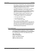
Safety notes Operator Guide Figure 2-2. Heated surface symbol WARNING Warnings indicate possible serious personal injury if you do not strictly follow the practice, procedure, condition, or statement that follows the WARNING. CAUTION Cautions indicate that possible system damage or data loss will occur if you do not carefully follow the practice, procedure, condition or statement that follows the CAUTION. Energy Star® The ENERGY STAR® Office Equipment Program is a team effort between U.S.
Operator Guide Safety notes Environmental Choice Labeling The DocuTech/DocuPrint 75/90 and DocuPrint 75 MX exhibits the Environmental Choice logo. It is imperative that the following statement be known: “Terra Choice Environmental Services, Inc. of Canada has verified that this Xerox product conforms to all applicable Environmental Choice EcoLogo requirements for minimized impact to the environment.
Safety notes Operator Guide WARNING Changes or modifications to this equipment not specifically approved by Xerox Europe may void user's authority to operate the equipment. Shielded cables must be used with this equipment to maintain compliance with the EMC Directive (89/336/EEC). WARNING This is a Class A product. In a domestic environment this product may cause radio interference in which case the user may be required to take adequate measures.
Operator Guide Safety notes • Austria • Belgium • Denmark • France • Finland • Germany • Greece • Iceland • Ireland • Italy • Luxembourg • Netherlands • Norway • Portugal • Spain • Sweden • Switzerland • United Kingdom In the event of problems, you should contact your local Xerox representative in the first instance.
Safety notes Operator Guide Electricity at Work Regulation - UK The Electricity at Work Regulation applies only to England and Wales. The Regulation The Electricity at Work Regulation 1989 came into force in England and Wales on the 1 April 1990. This 1989 Regulation places a duty on all employers and self-employed persons to ensure the electrical systems in their premises are constructed, maintained and operated in such a manner as to prevent, so far as reasonably practical, danger.
Operator Guide Answer Question Answer Safety notes The Electricity at Work Regulation 1989 came into force in England and Wales on 1 April 1990. This 1989 Regulation places a duty on all employers and self-employed persons to ensure the electrical systems in their premises are constructed, maintained and operated in such a manner as to prevent, so far as reasonably practicable, danger.
Safety notes Operator Guide Answer All employers and self-employed persons must ensure that the electrical systems in their premises are safe. This will include ensuring Xerox equipment in such premises is safe. Xerox Europe’s Product Safety function has prepared a guide which contains a list of tests which may be completed by your Xerox Europe Customer Service Organization. THESE TESTS MUST BE CARRIED OUT ONLY BY PERSONS WHO POSSESS THE RELEVANT SKILL, KNOWLEDGE AND EXPERIENCE TO CARRY OUT SUCH TESTS.
Operator Guide Safety notes Additional queries Please contact the Xerox Europe Technical Centre or your authorized Xerox representative if you have any queries regarding the information provided in this document. Electrical safety Attention to the following requirements ensures the safe operation of your equipment. Printer USA/Canada Europe The DocuTech/DocuPrint 75 printer requires a 115V AC outlet, dedicated 20 Amp, 3-wire circuit.
Safety notes Operator Guide • The power cord is the disconnect device for this printer. • Do not override or disable electrical or mechanical interlocks. • Do not push objects into slots or openings on the printer. Electrical shock or fire may result. • Do not obstruct ventilation openings. These openings prevent overheating of the printer. Controller USA/Canada Europe The controller requires a dedicated 115V AC 20 Amp grounded receptacle.
Operator Guide Safety notes • Do not obstruct ventilation openings. These openings prevent overheating of the controller. Printer power on/off indicator A power-on/power-off indicator shows the state of the power for the printer. This indicator is located on the top front of the printer and has a rectangular shape. This indicator glows green when printer power is on and emits no light, is colorless, when the printer power is off.
Safety notes Operator Guide Printer or controller - emergency power off If any of the following conditions occur, turn off the equipment immediately and disconnect the power cable from the electrical outlet. Contact an authorized Xerox Service Representative to correct the problem: • The equipment emits unusual odors, or makes unusual noises. • The power cable is damaged or frayed. • A wall panel circuit breaker, fuse, or other safety device has been tripped. • Liquid is spilled into the equipment.
Operator Guide Safety notes Printer - laser safety CAUTION The use of controls, adjustments or performance of procedures other than those specified in this guide may result in hazardous light exposure. This equipment complies with international safety standards and is certified as a Class 1 Laser Product. With specific regard to lasers, the equipment complies with laser product performance standards set by governmental, national, and international agencies as a Class 1 Laser Product.
Safety notes Do not do these Operator Guide • Always locate the printer in an area that has adequate ventilation and room for servicing. Refer to the space requirements in the DocuTech/DocuPrint 75/90 and DocuPrint 75 MX Installation Planning Guide. • Always use materials and supplies that are specifically designed for your Xerox equipment. Use of unsuitable materials may result in poor performance and possibly a hazardous situation.
Operator Guide Safety notes • Additional information Europe Additional information - all other areas DMO: Local Welcome Centre If you need any additional safety information concerning the equipment or the Xerox supplied materials, you may call the following number: 01707 353434 If you need any additional safety information concerning the equipment or the Xerox supplied materials, please contact the Xerox Welcome Centre.
Safety notes 2-16 Operator Guide DocuTech/DocuPrint 75/90 and DocuPrint 75 MX
3. Product overview This chapter will introduce the controller and overview the capabilities of the printer.
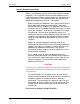
Product overview Operator Guide Figure 3-1. Ultra 10/Ultra 30 controller components CD Drive Power On/Off Power On/Off Disk Drive Figure 3-2. SunBlade 150 controller components Power On/Off Power On/Off CD Drive Disk Drive Printer components The main components of the printer are shown in Figure 3-3.
Operator Guide Product overview Figure 3-3. Printer components Tray 5 - Bypass Tray Top Tray Stacker Finisher Tray 6 High Capacity Feeder Trays 1 - 4 The following information sources are provided to assist you: • Power-on/power-off indicator is on the top front of the printer. It glows green when on and emits no light when off. • Labels are affixed at the points of need throughout the system. They depict information about loading the paper stock. • Green or Gold colored areas act as markers.
Product overview Operator Guide Figure 3-4. Trays 1- 4 Trays 1 - 4 The Paper Trays hold up to 500 sheets of 20 lb (75 gsm) stock each. You can adjust the trays to hold many sizes of paper, from 5.5 x 8.5 inches (140 x 216 mm) up to 11 x 17 inches (279 x 432 mm or A3). To handle 12 x 18 inch paper, a tray must be specially set up. Please contact the Xerox Welcome Centre to handle this size paper. If you wish to dedicate a tray permanently to handle this size paper please contact the Xerox Welcome Center.
Operator Guide Product overview Figure 3-5. Tray 5 Bypass Tray Tray 5 High Capacity feeder (tray 6) The High Capacity Feeder (Tray 6) is located under the Bypass Tray and saves you from having to load the other individual paper trays with 8.5 x 11 inch (216 x 279 mm) paper often. The High Capacity Feeder can only feed 8.5 x 11 inch (216 x279 mm) or A4 Long Edge Feed (LEF) paper and cannot be adjusted to hold any other sizes or orientations.
Product overview Operator Guide Figure 3-6. Tray 6 High Capacity Feeder Tray 6 High Capacity Feeder Reloading Paper Open the cover and wait for the tray to lower in order to reload paper. Fill the tray only to the maximum-fill line on the left side of the tray. After reloading paper, close the cover to raise the tray. The High Capacity Feeder can also accommodate 8.5 x 11 inch (216 x 279 mm) drilled or long-edge paper between 16 to 32 lb (75 to 120 gsm).
Operator Guide Product overview Loading paper in Trays 1-4 1. Pull out the paper tray. Refer to the tray labels as you load the paper neatly in the tray. Make sure that the left edge of the paper stack is against the bar that is located on the left-hand edge of the tray, as shown in the top portion of Figure 3-7. Do not load paper above the maximum fill line. Figure 3-7. Loading Trays 1-4 2. Ensure that the paper tray edge guides are against the top, bottom, and side edges of the paper.
Product overview Operator Guide Insert paper as shown. The Bypass Tray extends to accommodate paper that is physically longer than the tray. Simply pull out the extension bar. Do not load paper above the maximum fill line. Loading paper in the High Capacity Feeder (Tray 6) To load paper, open the cover and wait for the tray to lower. When the paper has been loaded, close the cover to raise the tray. The High Capacity Feeder is shown in Figure 3-8. Figure 3-8.
Operator Guide Product overview Figure 3-9. Changing the guides from 8.5 x 11 inches to A4 Rear Guide Starting with the Rear Guide, you will adjust the guide to the A4 position. Perform the following: 1. Slide the black latch down to release the guide. 2. Move the guide out, over, and in, into the A4 position. 3. Slide the latch up to lock the guide. Front Guide Repeat the procedure for the front guide NOTE: Be sure to reprogram the tray in the Printer Manager to reflect the changed size.
Product overview Front Guide Operator Guide Repeat the procedure for the front guide NOTE: Be sure to reprogram the tray in the Printer Manager to reflect the changed size. Finisher The Finisher consists of the Top Tray and the Stacker Tray, as shown below in Figure 3-10. Figure 3-10. Finisher components Top Tray Finisher button Stapler is within the finisher Press the Finisher Button to unload the Stacker Tray during a print run Top Tray The Top Tray holds up to 250 prints.
Operator Guide Product overview Stapling Removing any of the output while the printer is running may produce finished sets that are incorrectly stapled. To ensure that the stapling of thin sets is satisfactory, the printer performs the following actions. After 30 finished sets of 15 sheets, the printer: 1. cycles down 2. raises a message to empty the Stacker 3. waits until the sets are removed 4. raises the Stacker Tray 5. cycles up and resumes printing.
Product overview Operator Guide Unloading the Stacker during printing If it is necessary to unload the Stacker during printing, use the following procedure: 1. Press the Finisher button. 2. Wait for the printer to finish producing the set being printed. 3. Wait while the Stacker Tray is automatically lowered. 4. Unload the Stacker Tray. 5. Press the Finisher button again to continue operations.
Operator Guide Product overview Controller software The controller runs the DocuSP Print Services software. This software gives the printer operator the ability to manage the jobs and the printer. For detailed information on how to use the DocuSP Print Services software, refer to the DocuSP on-line Help. Modems The controller has an external modem that is on or off according to the site requirements for this modem or as needed by Xerox service.
Product overview 3-14 Operator Guide DocuTech/DocuPrint 75/90 and DocuPrint 75 MX
4. Maintenance You will first power on the controller and then power on the printer. Power-on procedures Your Xerox DocuTech/DocuPrint 75/90 and DocuPrint 75 MX system is designed to maximize printer performance. This includes using a short paper path in order to reduce jams, and Customer Replaceable Units (CRUs) in order to avoid extended periods of downtime.
Maintenance Operator Guide Figure 4-1. Ultra 10/Ultra 30 controller power-on button and LED Power On/Off and LED Figure 4-2. SunBlade 150 controller power-on button and LED Power On/Off and LED To power on the controller: 1. Switch on the power for each of the connected peripherals. 2. Switch on the monitor. 3. Press the controller “On” button. 4. Confirm that the controller LED light is on. NOTE: For an Ultra 10, you need to power off the system from the back of the controller.
Operator Guide Maintenance Printer power-on procedure When the printer is on, the power-on/power-off indicator glows green. The printer must be switched on by pressing a switch on the printer. The printer cannot be powered on from the DocuSP Print Services interface that runs on the controller. The printer power switch is shown in Figure 4-3.
Maintenance Operator Guide Power-off procedures You can power off only the printer and allow the controller to keep on processing jobs, or you can power off both the printer and the controller. Printer power-off When the printer power is off, the power-on/power-off indicator does not emit light, it is colorless. Under normal operating conditions the printer should be powered off using the DocuSP Print Services on the controller, rather than by pressing the printer on/off switch.
Operator Guide Maintenance Figure 4-4. Printer power-off Printer Power-Off Using The Red Button A red button, located inside the printer, provides a less gentle method for powering off the printer. This power-off procedure immediately cuts power to the printer in an uncontrolled manner without confirmation or delay. Any jobs in the queue will be immediately lost without confirmation.
Maintenance Operator Guide Figure 4-5. Printer power-off, red button RED BUTTON After the Red Button is used, the printer will take longer to reboot. Energy Saver The Energy Saver option for the DocuTech 75/DocuPrint 90 will enter the printer into a “low power mode” after 60 minutes of nonusage. This mode will continue until a job is submitted. The System Administrator can change the Energy Saver time to a shorter or longer period.
Operator Guide Maintenance CAUTION Before switching off the controller, exit any applications that are running and shut down the DocuSP Print Services using the Shutdown option so that you do not lose any data. 3. On the Print Services System menus, select the Shutdown option. (Shutdown also powers off the printer.) 4. Answer the confirmation prompt. If there are jobs still being processed, the system will request confirmation before starting the shutdown. 5.
Maintenance Operator Guide Figure 4-6. Ultra 10/Ultra 30 controller power-on button and LED Power On/Off and LED Figure 4-7. SunBlade 150 controller power-on button and LED Power On/Off and LED 6. Verify that the controller front panel LED is off and that the controller fans are not spinning. 7. Switch off external devices or any peripherals. 8. Switch off the monitor. 9. Disconnect the cables to any peripheral equipment.
Operator Guide Maintenance CAUTION When the power on/standby switch is in stand-by and the AC power cord remains connected to a power receptacle, AC voltage is present in the power supply. 10. If the equipment will be serviced or moved, disconnect the AC power cord from the AC receptacle. Emergency power-off procedures An emergency power-off procedure may be used when the power must be switched off immediately. CAUTION The controller emergency power off procedure may corrupt the DocuSP software.
Maintenance Operator Guide • The power cable is damaged or frayed. • A wall panel circuit breaker, fuse, or other safety device has been tripped. • Liquid is spilled into the equipment. • The equipment is exposed to water damage or flood. • Any part of the equipment is physically damaged.
Operator Guide Maintenance Figure 4-8. Jam clearance areas Area 1 Sheets may be left in this area when jams occur. Area 2 The Lift Handle: The printer is programmed to circulate paper to this area in the event of a jam. Raise the handle to clear this area. Do not move the handle to the left. Ensure that the handle is fully locked by lowering it before closing the Front Door or the handle may be blocked or damaged. Area 3 The Fuser area: This area includes areas 3b, 3c, and 3d.
Maintenance Operator Guide Area 5 To access Areas 5, 5a, and 5b you need to open the Finisher area. The Finisher area is shown in Figure 4-9. Lift and pull Handle 5 to get access to paper in areas 5a and 5b. Figure 4-9. Finisher area Area 7 4-12 To access Area 7, you need to open the High Capacity Feeder (Tray 6) and Bypass Tray (Tray 5) areas. The High Capacity Feeder and the Bypass Tray are shown in Figure 4-10. Lift and pull the top cover of the Bypass Tray to access area 7a.
Operator Guide Maintenance Figure 4-10. Access to area 7 Replaceable units and supplies The printer is designed to allow the customer to change major components such as the Xerographic Module, the Fuser Module, the Developer Collector Bottles, the Dry Ink Cartridge (Toner), or the Feed Roll Cartridges without having to initiate a service call. These and other replaceable supplies are shown in Figure 4-11.
Maintenance Operator Guide Figure 4-11. Location of CRUs and supplies 1. Ink Cartridge (Toner Cartridge) - a consumable supply 2. Fuser Module - a Customer Replaceable Unit (CRU) 3. Xerographic Module - a Customer Replaceable Unit (CRU) 4. Paper Feed Roll Cartridge (1 per paper tray including trays 5 and 6) - a Customer Replaceable Unit (CRU) 5. Developer Collector Bottle (included as part of the Xerographic Module) - a Customer Replaceable Unit (CRU) 6.
Operator Guide Maintenance • Developer Collector Bottle If a replacable item must be changed, a message will appear on the controller. To replace these units, simply follow the instructions provided with each replacement box. The fusers are to be retained for repair or returned by the Service Representative. The Xerographic CRU is still a customer replaceable unit and can be returned in the box with the prepaid return label.
Maintenance Operator Guide When placing orders, give the representative the following information: • Your Xerox customer number • Your system model name and number • A description of the item • The quantity of the item Dry Ink (Toner) usage and “Dry Ink Low” message Dry ink (toner) usage is related to the amount of area that needs to be printed (covered).
5. Paper and other stock Your printer can process a variety of paper and other stock to accommodate your needs. This chapter contains information about the stock you can use in the printer and how you can expect it to perform. Stapling guidelines and the correct loading of special stocks is also discussed as well as stock storage requirements. Performance information The following tables list the printer performance expectations for both one-sided and two-sided printing, on paper and on other stock.
Paper and other stock Operator Guide Figure 5-1. Size requirement for duplex printing This edge must be between 6.7 to 18 inches (170 to 457 mm) to be printed on both sides (duplexed). Feed Direction The dimension of this edge is controlled by the tray. Tray capabilities: The trays are shown in Figure 5-2. Figure 5-2. Tray capabilities Tray 5 Tray 6 Trays 1 - 4 Tray 5 5-2 The Bypass Tray has a capability of 4 to 12 inches (102 to 305 mm); 5.83 to 18 inches (148 to 457 mm).
Operator Guide Paper and other stock Tray 6 The High Capacity Tray has a capability of only 8.5 x 11 inch (216 to 279 mm) or A4 long-edge feed (LEF), between 16-32 lb (75-120 gsm). Trays 1-4 Have a capability of 8 to 17 inches (203 to 432 mm); 5.25 to 11 inches (133 to 279 mm). Call the Welcome Center if you want to permanently set any of the Trays 1-4 to process 12 x 18 inch (305 x 457 mm) stock.
Paper and other stock Operator Guide Table 5-1. Staple capability for various paper weights Weight Maximum Number of Stapled Sheets 32 lb or 120 gsm 33 65 lb or 244 gsm Cover to 110 or 203 gsm Index 22 When the Top Tray of the Finisher is used: In addition to using the Top Tray as an output location, it is also used for short-edge feed (SEF) sheets less than 6.
Operator Guide Paper and other stock c = Requires a Xerox technical specialist to permanently set up any of the trays 1-4 to handle 12 x 18-inch (305 x 457 mm) paper. After any one of these trays is set up to handle this size, it cannot run other sizes. Tray 5, however, can be used without any special set-up intervention from Xerox. d = For the correct paper loading orientation refer to the paper tray label or to Table 5-6.
Paper and other stock Operator Guide The printer performance for trays using standard 20 lb (75 gsm) paper in common USA sizes is shown in Table 5-2. Table 5-2. Printer performance for standard paper 20 lb (USA) Rating Size Feed Trays 1-4 Tray 5 Tray 6 Note Letter 8.5 x 11 in. (216 x 279 mm) LEF l l l SEF o o x SEF o o x SEF l l x 5.5 x 8.5 in. (140 x 216 mm) SEF o o x b 5 x 7 in. (127 x 177.
Operator Guide Paper and other stock The printer performance using standard 80 gsm paper in common Xerox Europe sizes is shown in Table 5-3. Table 5-3. Printer performance for standard paper 80 gsm (Xerox Europe) Rating Size Feed Trays 1-4 Tray 5 Tray 6 Note A3 297 x 420 mm (11.7 x 16.54 in.) SEF l l x LEF l l l SEF o o x LEF o o x SEF o o x LEF x u x a SEF o o x b SEF x o x a, b SEF l l x LEF x o x SEF l l x b SEF x u x b 215 x 330 mm (8.
Paper and other stock Operator Guide The printer performance for non-standard paper and other types of stock is shown in Table 5-4. You may run the stock if you follow the guidelines in the table and if the dimensions of the stock are within the size limits previously discussed for standard paper. Table 5-4.
Operator Guide Paper and other stock The printer performance for new and recycled 8.5 x 11 inches (216 to 279 mm) or A4 paper for various weights is shown in Table 5-5. Table 5-5. Printer performance for new and recycled plain paper Paper Weight Throughput Material 8.5 x 11 in.
Paper and other stock Operator Guide Table 5-6. Recommendations for loading special stock Stock Type Recommendation • Use ultra-violet cured or oxidative inks to extend the life of the Feed Roll Cartridges. • Load face up in Trays 1-4. • Load face down in Trays 5-6. Reinforced Mylar Ringed binders edge • Load reinforced edge on the right in Trays 1-4. 3 or 4 holes • Load reinforced edge on the left in Trays 5-6. • Use long-edge feed only.
Operator Guide Paper and other stock Table 5-6. Recommendations for loading special stock Stock Type Labels Common Use Self-adhesive labels for envelopes and packaging Recommendation • Do not duplex. • Feed labels into the printer LEF only. Labels pose a special problem because, depending on the number of labels per sheet, there is an opportunity for the label to separate from the backing while inside the printer.
Paper and other stock Operator Guide Loading and handling Before loading paper, unwrap the paper from the moisture resistant wrappings, discard the wrapper and insert the paper in the tray. If it is special stock such as punched paper follow the orientation label on the tray or the recommendations in Table 54. and Table 5-6. of this chapter. Fanning the paper edges is not required, but may be beneficial with certain stocks in dry environments.
6. Problem solving This chapter will assist you in avoiding problems and solving those that may occur. It also provides information on how to contact the Welcome Center. Avoiding the problems A variety of situations can affect the quality of the printer output. For optimal performance, follow these guidelines: • Do not locate the printer in direct sunlight or near a heat source such as a radiator. • Avoid sudden changes in the environment surrounding the printer.
Problem solving Operator Guide Solving the problems Recommendations for solving some common problems are listed in Table 6-1. Table 6-1. Troubleshooting tips Problem Symptom Controller/ Printer The printer is not receiving jobs from the controller or will not go on when switched on. • Check to see if the cable that connects the controller to the printer is plugged in correctly. Each end of the cable has a plug that is keyed for correct fit.
Operator Guide Problem solving Table 6-1. Troubleshooting tips Problem Stock handling Stock handling Symptom There are repeated stock jams or misfeeds in Tray 5. There are repeated shut downs from jams in Area 3 or the prints show an unexpected image shift when feeding from Tray 5. DocuTech/DocuPrint 75/90 and DocuPrint 75 MX Recommendation • Ensure that the correct stock size is displayed on the Print Services, Printer Manager window. • Remove the stock and reload the tray.
Problem solving Operator Guide Table 6-1. Troubleshooting tips Problem Stock handling Stock handling Symptom There are jams inside the printer. The stock curls up or down. Recommendation • Check the paper path for obstruction. • Make sure that the Area 2 Lever is in the correct position (down). • Flip the stock over in the tray. • Ensure that the Edge Guides are adjusted to touch the sides of the stock.
Operator Guide Problem solving Calling the Welcome Center If you are experiencing difficulty with your printer, check the troubleshooting tips shown in Table 6-1. Attempt to solve the problem before contacting the Welcome Center. You might be able to resolve the situation quickly. If the difficulty persists, contact the Xerox Welcome Center. The Welcome Center telephone number and other relevant information are conveniently located on the Diagnostics window.
Problem solving 6-6 Operator Guide DocuTech/DocuPrint 75/90 and DocuPrint 75 MX