Xerox DocuPrint 4850/4890 IPS Guide to Performing Routine Maintenance Version 7.
Xerox Corporation Printing Systems Documentation and Education 701 South Aviation Boulevard, ESM1-058 El Segundo, CA 90245 ©1997, 1998, 1999, 2000 by Xerox Corporation. All rights reserved. Copyright protection claimed includes all forms and matters of copyrightable material and information now allowed by statutory or judicial law or hereinafter granted, including without limitation, material generated from the software programs which are displayed on the screen, such as icons, screen displays, looks, etc.
Laser safety ! Warning: Adjustments, use of controls, or performance of procedures other than those specified herein may result in hazardous light exposure. The Xerox DocuPrint printers are certified to comply with the performance standards of the U.S. Department of Health, Education, and Welfare for Class 1 laser products. Class 1 laser products do not emit hazardous radiation.
Operation safety Your Xerox equipment and supplies have been designed and tested to meet strict safety requirements. They have been approved by safety agencies, and they comply with environmental standards. Please observe the following precautions to ensure your continued safety. • Always connect equipment to a properly grounded electrical outlet. If in doubt, have the outlet checked by a qualified electrician.
Table of contents Laser safety iii Ozone information iii Operation safety iv Introduction vii About this guide vii Contents Conventions Related publications 1. 2. Feeder trays viii ix x 1-1 Checking feeder trays 1-1 Loading feeder trays 1-2 Guidelines for loading paper 1-2 Loading the trays 1-3 Output trays 2-1 Checking and unloading dual stacker trays 2-1 Checking and unloading the stitcher/stacker tray 2-3 Checking and unloading the sample tray 2-4 3. Stitcher wire 3-1 4.
TABLE OF CONTENTS 7. 8. 9.
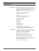
Introduction The Xerox DocuPrint 4850/4890 IPS Guide to Performing Routine Maintenance describes how to perform basic maintenance on the Xerox DocuPrint 4850/4890 IPS. About this guide This guide is designed for operators whose job consists of operating each of the system components, running print jobs, solving simple system problems, and performing basic maintenance tasks, such as replenishing printer supplies.
INTRODUCTION Contents This section lists the contents of this guide. • Chapter 1, “Feeder trays,” provides information on how to load feeder trays. • Chapter 2, “Output trays,” describes how to unload output trays for the DocuPrint printer. • Chapter 3, “Stitcher wire,” provides information on how to continue printing when the spool is out of wire. • Chapter 4, “Fuser lubricant and pressure roll wiper,” describes how to refill the fuser agent reservoir, and how to replace the pressure roll wiper.
INTRODUCTION Conventions This guide uses the following conventions: • Italics — Document and library names are shown in italics (for example, the Xerox DocuPrint 4850/4890 IPS Guide to Performing Routine Maintenance). • Capitalization of graphical user interface (GUI) window titles matches the titles as they appear on the screen. In cases where a window does not have a title, it is referenced using all lower case.
INTRODUCTION Related publications This document is part of the Xerox DocuPrint IPS publication set. Xerox documents Following is a list of all Xerox DocuPrint IPS documents. For a complete list and description of available Xerox documentation, refer to the Xerox Customer Documentation Catalog (publication number 610P17517), or call your service representative.
1. 1Feeder trays This chapter describes the processes for loading paper in the 4850/4890 IPS feeder trays, and explains what actions are necessary if a paper stock is changed. Checking feeder trays Check the amount of paper in each feeder tray by examining the green lights on the door of the tray. Each light represents 25 percent of a ream, or about 125 sheets of 20-pound or 80 gsm (grams per square meter) paper.
FEEDER TRAYS Loading feeder trays It is important to load paper properly in the feeder trays to prevent jams and loss of production time. The following guidelines will help ensure maximum efficiency of your IPS printer’s operation. Guidelines for loading paper When you are loading the paper, follow these guidelines to prevent paper jams: 1-2 • • • • • • Remove damaged sheets. • When loading predrilled paper, fan the paper and remove loose paper plugs.
FEEDER TRAYS Loading the trays Follow these steps to load a feeder tray: 1. If the Ready To Open indicator on the feeder tray door is not lit, press the Tray Unlock button and wait for the tray to descend and the Ready To Open indicator light before opening the tray. 1 2 1 2 Ready to Open Indicator Tray Unlock button 2. Lift and pull on the bar along the top of the feeder tray. Slide the tray all the way out for best access and ease of loading.
FEEDER TRAYS 3. Press the green lever down to unlatch the paper feeder assembly. Caution: Attempting to move the lever in any other direction can break it. 4. Pull out any partially fed paper from the feeder assembly and discard it. There will be some resistance. 5. Squeeze the lever against the back of the length guide and slide the guide toward the back of the printer. 6. Remove any paper remaining in the tray and set it aside to be placed on top of the new paper.
FEEDER TRAYS 7. Load paper, following the instructions at the front of the feeder tray and carefully positioning the paper in the right-front corner of the tray. 8. Pull the length guide forward to touch the back of the paper stack. 9. Latch the paper feeder assembly by pressing the green dot next to the green release lever until the assembly clicks into position. 10. Slide the tray into the printer until it latches. The tray rises automatically into position. 11.
FEEDER TRAYS Note: When you change the paper size in one of the feeder trays, a message displays asking you to make sure the printer is warmed up, ready, and loaded with the proper media. The message displays the media defined for the tray, as well as the paper currently loaded in the tray. Currently, there is no method of restoring the Input Configuration to its original state. Once you select Modify, the Input Configuration window appears.
2. 2Output trays Your print jobs are sent to printer output trays, which you must unload. You can unload each of the output trays while the system is printing. How you do so, however, depends on the type of tray. This chapter discusses how to check and unload the types of trays available. In all cases, if the printer has stopped due to a full output tray and does not resume automatically when the tray is emptied, press the Continue button on the printer control console.
OUTPUT TRAYS Unloading the dual stacker trays To unload each dual stacker tray, raise the scuffer arm and remove the printed pages. 1 2 1 2 Scuffer arm Tray Full indicators Note: When both trays are full, you must empty at least one tray before you can resume printing. Note: Your service representative can set up your printer so that printing continues automatically after a dual stacker tray is unloaded and replaced.
OUTPUT TRAYS Checking and unloading the stitcher/stacker tray An electronic counter in the stitcher/stacker keeps track of the number of sheets printed and the number of stapled sets produced. When a stacker tray is full, the following occurs: • Printing stops and a message appears on the printer control console that the output tray is full. • The attention light shines steadily. Note: A false tray full condition may occur when you remove small stapled sets without pulling the tray out.
OUTPUT TRAYS Checking and unloading the sample tray The sample tray holds up to 100 sheets of paper from 8.5 by 11 inches / 216 by 279 mm to 8.5 by 14 inches / 216 by 356 mm. A message appears when the sample tray is about to fill, as well as when it is full. Because a paper jam can occur if the tray is overfilled, empty the sample tray regularly if it is in use. To empty the sample tray, remove the printed pages. Note: The sample tray can receive purged sheets after a paper jam.
3. 3Stitcher wire The Wire Percentage indicator is located on the printer control console of IPS systems configured with a stitcher/stacker. The indicator displays approximate percentage of stitcher wire remaining on the spool. Your service representative can set the display to flash at a predetermined percentage as a warning that you are running low on stitcher wire. Figure 3-1.
STITCHER WIRE If you continue printing the job without replacing the wire, the documents print without being stapled. The printer status display shows the following message: OUT OF WIRE Contact your key operator or your service representative when you see this message. This should seldom happen because your service representative checks the wire supply on each service call and replaces the spool as needed. To continue printing without replacing the wire, press the Continue button.
4. 4Fuser lubricant and pressure roll wiper This chapter describes how to add fuser lubricant and how to replace the pressure roll wiper on your system. Adding fuser lubricant The fuser uses heat to fuse the print image to the paper. It is critical that the fuser be kept lubricated with fuser lubricant and that its reservoir be kept full. This chapter describes the procedure for adding fuser lubricant in the printer. Your service representative usually adds fuser lubricant.
FUSER LUBRICANT AND PRESSURE ROLL WIPER 5. Put on gloves. ! Warning: Fuser lubricant contains silicone, which can cause eye irritation upon contact. Wash your hands with soap and water after you finish this procedure. 6. Locate the fuser reservoir and remove the cap by turning it counter-clockwise. Caution: There is an orange float that indicates the lubricant level. It may stick to the reservoir wall. Be careful not to overfill the reservoir or an overflow of lubricant may occur.
FUSER LUBRICANT AND PRESSURE ROLL WIPER 7. Open a tube of fuser lubricant and cut the pointed spout diagonally. Carefully squeeze the lubricant into the reservoir until the orange float reaches the top (C), or until you see the oil reach the top edge below the fuser cap. The reservoir may require up to two tubes of lubricant if it was empty. C 8. Replace the reservoir cap by turning it clockwise. 9.
FUSER LUBRICANT AND PRESSURE ROLL WIPER 11. Remove and dispose of the gloves in a trash receptacle, being careful not to let any residue come in contact with your skin. 12. Close the printer doors. 13. Wash your hands to remove any fuser lubricant. Replacing the pressure roll wiper You need to replace the pressure roll wiper when any of the following occur: • • • Excessive oil or dirt buildup appears on the wiper. The first few prints of a job have oil or dirt on them.
FUSER LUBRICANT AND PRESSURE ROLL WIPER 4. Determine if the fuser is cool. Place your hand approximately 1 inch (25mm) above the fuser area. If you feel heat, STOP, leave the fuser drawer out, and wait for the fuser to cool. DO NOT touch the fuser while it is hot. If you DO NOT feel heat, continue with the procedure. Warning: Perform this task only when the fuser is cool. Exercise care to prevent burns when working in this area. Do not perform this task if the fuser is hot. ! 5. ! Put on gloves.
FUSER LUBRICANT AND PRESSURE ROLL WIPER 6. Locate the pressure roll wiper assembly and release the top rod by pulling upward as shown. 7. Remove the lower rod from the springs and lift the wiper assembly away. 8. Place the used wiper in the plastic bag that came with the new wiper and dispose of the bag in a trash receptacle.
FUSER LUBRICANT AND PRESSURE ROLL WIPER 9. Rotate the pressure roll while wiping the dirt off with a clean cloth. Discard the cloth in the trash receptacle when you are finished. 10. Insert the short rod in the upper loop of the new wiper. 11. Insert the long rod through the lower loop of the new wiper. 12. Insert the lower rod into the springs on both ends of the pressure roll. Caution: Make sure the smooth side of the wiper is facing the pressure roll.
FUSER LUBRICANT AND PRESSURE ROLL WIPER 13. Center the wiper on the pressure roll. Pull up the wiper and place the upper rod onto the brackets on both ends of the pressure roll, as shown. 14. Remove and dispose of the gloves in a trash receptacle, being careful not to let any residue come in contact with your skin. 15. Close the fuser drawer by pressing down on the green latch (A), and push the fuser drawer in until it latches in place. A 16. Close the printer doors and power on the printer. 17.
5. 5Inks Dry ink is the black or colored powder that forms the image on the printed page. This chapter describes the procedure for adding dry ink to the printer. This chapter also describes the procedure to change the Customer Changeable Unit (CCU) that allows additional colors to be used. Adding dry ink You do not need to monitor the amount of dry ink remaining in the bottle at any given time; the system monitors it for you.
INKS To add dry ink: 1. Open the printer doors and locate the dry ink area on the left side of the printer. Note: When you replace colored dry ink, it is not necessary to remove the CCU from the printer. 2 1 1 2 Colored dry ink bottle Black dry ink bottle 2. Spread a dropcloth on the floor under the dry ink area. 3. Pull the empty dry ink bottle toward you until it stops. Caution: If there is still dry ink in the bottle, the ink may spill as you move the bottle back onto its lid.
INKS 4. Remove the empty bottle and discard it. 5. Shake the new ink bottle at least ten rotations, taking care to support the bottle cap. It is important that you mix the contents thoroughly by allowing the material inside the bottle to fall and settle toward the label side at each rotation. Note: Both black and colored dry ink contain a mixture of toner and developer material.
INKS 7. Hold the cartridge in place and pull the paper seal off the mouth of the bottle. 8. Discard the seal along with the dropcloth. Caution: If any dry ink gets on your hands, wash them with soap and cold water. If any dry ink gets on your clothes, brush them with a dry paper towel or a stiff-bristled brush. If this does not remove the ink, immediately launder with detergent and cold water. Heat sets the ink permanently.
INKS Exchanging Customer Changeable Units (CCUs) You need to exchange the currently loaded CCU in either of the following situations: • A print job requires another colored dry ink to be loaded. When a document is in the color housing wait state, change the housing unless you decide to cancel the job. • The color housing is faulty. If you have more than one CCU, you should replace the faulty color housing and continue to print documents that do not require a specific color.
INKS Removing the CCU To remove the CCU from the printer, follow these steps. 1. When the printer is not cycled down, always press the Stop button on the printer control console before you open the door and attempt to remove the CCU. 2. Open the printer doors and locate the color housing area on the left side of the printer.
INKS 3. Open the top cover of an empty cart. 1 4 3 1 2 3 4 2 Gold alignment knob Top cover Pedal Pallet 4. Push the cart up to the printer, lining up the gold knob on the cart with the gold recess on the printer inner cover. 5. Push the cart firmly against the printer until you can feel the two latch together.
INKS 6. Push firmly on the cart pedal until you hear or feel the pedal catch. The pedal should stay locked down. The pallet within the cart is raised. 7. Turn the backup roller handle clockwise for a quarter turn to an upright position.
INKS 8. Turn the CCU latch handle clockwise for a quarter turn. 9. Using the CCU latch handle, pull the CCU out of the printer until it is completely in the cart. 10. Push down firmly on the cart pedal until you hear or feel a click. The pallet, which now contains the CCU, is lowered into the cart. If the pallet does not move, check that the CCU is all the way out of the printer and push down on the pedal again.
INKS 11. Close the cart top cover and store the cart.
INKS Inserting a CCU To insert a CCU, follow these steps. 1. Open the top cover of the cart containing the new color CCU. Note: CCUs are not interchangeable between printer models. Make sure you order and use the one designed for your printer. 2. Push the cart up to the printer, lining up the gold knob on the cart with the gold recess on the printer inner cover. 3. Push the cart firmly against the printer until you can feel the two latch together. 4.
INKS 7. Turn the backup roller handle counterclockwise for a quarter turn. 8. Push down firmly on the cart pedal until you hear or feel a click. If the pallet does not drop, check that the CCU is all the way in the printer and the pallet is released, then push down on the pedal again. 9. Remove the cart from the printer and close the cart top cover. 10. Close the printer doors. 11. Store the cart.
INKS Storing the cart and CCU Note: If any dry ink gets on your hands, wash them with soap and cold water. Heat sets the ink permanently. If any dry ink gets on your clothes, brush them with a dry paper towel or a stiff-bristled brush. If this does not remove the ink immediately, launder with detergent and cold water. Dry cleaners should be told that the spot is dry ink for a printer, so they will not use a solvent that sets the stain.
INKS 5-14 XEROX DOCUPRINT 4850/4890 IPS GUIDE TO PERFORMING ROUTINE MAINTENANCE
6. 6Waste containers The waste container in the DocuPrint 4850/4890 IPS collects dry ink and developer after it has been used by the printer. When the container becomes full, it must be replaced, or the printer eventually stops printing. This chapter contains the procedures for replacing the dry ink and developer waste container.
WASTE CONTAINERS To replace the waste container: 1. Open the printer doors and locate the dry ink cartridge at the left side of the printer. The developer waste container is located under the color dry ink bottle. 2. Spread a dropcloth on the floor under the developer waste container area. 3. Hold the container by the tab on the top. Lift the container up approximately half an inch, then pull it out of the printer. Let the tab-end of the container touch the floor, then grasp the container by the handle.
WASTE CONTAINERS 4. Use the cap from the new container to recap the old container. 5. Discard the waste material and container according to the instructions on the label. 6. Grasp the new, empty container with both hands, one hand on the handle and one on the container tab. Lift the front of the container over the notch at the front of the compartment, so that the notch slides into the groove running underneath the container. 7. Make sure that the container is pushed all the way into the compartment. 8.
WASTE CONTAINERS Replacing the 4850 dry ink waste container To replace the dry ink waste container: 1. Open the service door at the rear of the printer by grasping the handle and pulling the door out and down. 2. Grasp the container handle and pull the container up and out over the ridge at the base of the storage compartment. A full dry ink waste container weighs about 15 pounds/6.8 kg. 3. Place the cap, which is tethered to the bottle, onto the mouth of the container.
WASTE CONTAINERS 4. Discard the dry ink waste container according to the instructions on the label. Once the waste container is removed, the message DRY INK WASTE CONTAINER NOT PRESENT displays on the printer control console, and the printer remains idle until a new container is inserted. 5. Remove the cap from the new dry ink waste container. 6. Align the waste container with the support guides and slide the container into the storage compartment, gently lifting it up and over the ridge. 7.
WASTE CONTAINERS Replacing the 4890 dry ink waste container To replace the dry ink waste container: 1. Open the service door at the rear of the printer by grasping the handle and pulling the door out and down. 2. Grasp the container handle and pull the container up and out over the ridge at the base of the storage compartment. A full dry ink waste container weighs about 15 pounds/6.8 kg. 3. Place the cap, which is tethered to the bottle, onto the mouth of the container. 4.
WASTE CONTAINERS 5. Remove the cap from the new dry ink waste container. 6. Align the waste container with the support guides and slide the container into the storage compartment, gently lifting it up and over the ridge. 7. Close the rear door. A beep signals that the replacement is complete.
WASTE CONTAINERS 6-8 XEROX DOCUPRINT 4850/4890 IPS GUIDE TO PERFORMING ROUTINE MAINTENANCE
7. 7Bypass transport The bypass transport is installed in tray 1 of the dual stacker on the DocuPrint 4890 IPS. This chapter describes how to remove and install the bypass transport. Figure 7-1.
BYPASS TRANSPORT Removing the bypass transport Follow these steps to remove the bypass transport from the printer: 1. Power off the printer. 2. Disconnect your finishing device following the instructions provided with the device. 3. Unplug the two cables from the rear of the bypass transport. 4. Open the front cover of the bypass transport and unlock the transport by turning the green handle counterclockwise one quarter turn.
BYPASS TRANSPORT 5. Grasp the recessed handles on the front and rear of the bypass transport and slide the transport out of the tray toward the front of the printer. 6. Place the transport in its storage location. 7. Press downward on the scuffer arm in stacker tray 1 until it rests in the tray. Note: The bypass transport support remains in place. It is permanently attached to your printer. 8. Power on the printer.
BYPASS TRANSPORT Installing the bypass transport Follow these steps to install the bypass transport: 1. Power off the printer. 2. Raise the scuffer arm in stacker tray 1 to its highest position. (A spring holds the scuffer arm in the raised position.) 3. Lift the bypass transport assembly by the front and rear recessed handles and slide it into stacker tray 1 as far as it will go.
BYPASS TRANSPORT 4. Open the front cover of the bypass transport and lock the transport by turning the green handle clockwise one quarter turn. (You will feel some resistance.) 5. From the rear of the dual stacker module, plug the two cables into the rear of the bypass transport. 6. Connect your finishing device following the instructions provided with the device. 7. Power on the printer.
BYPASS TRANSPORT 7-6 XEROX DOCUPRINT 4850/4890 IPS GUIDE TO PERFORMING ROUTINE MAINTENANCE
8. 8Cleaning This chapter describes the cleaning tasks you need to perform regularly on the DocuPrint 4850/4890 IPS. Cleaning the keyboard, monitor, and the exterior of the Printer Controller Clean the exterior surfaces of your Printer Controller, including monitor and keyboard, as required. Clean daily, if possible. Use the following supplies to clean the exterior surfaces: • Monitor: Use a soft, lint-free cloth dampened with a glass cleaner.
CLEANING Cleaning the 4mm cartridge tape drive Clean the 4mm cartridge tape drive every 25 hours of actual tape operation. Use only a cleaning cartridge designed for the 4mm cartridge tape drive. No fluids or other preparations are necessary with the use of these cartridges. Caution: Do not use cleaning cartridges or any types of fluids designed for use in audio devices as these can damage your tape drive. To clean the tape drive: 1.
9. 9Maintenance and support services This chapter provides information on the services Xerox provides to help you keep your DocuPrint printer running efficiently. It describes the services available to you and how to take advantage of these services. Note: The support services described in this chapter apply to the United States only. For information on the support services available internationally, consult your Xerox representative.
MAINTENANCE AND SUPPORT SERVICES Xerox Documentation and Software Services XDSS distributes the documents you need to install and use the DocuPrint printer, other Xerox printers, and associated software. If you register for site subscription service, XDSS will automatically send you updates and revisions as they become available. To order this documentation, call Xerox Documentation and Software services: 1-800-327-9753 (U.S. only), between the hours of 6:00 a.m. and 4:00 p.m., Pacific time.
MAINTENANCE AND SUPPORT SERVICES Xerox Customer Education Xerox offers classes and tutorial documents on various topics relating to printing systems and document production. For information about Xerox training courses, or to receive a catalog, call Xerox Customer Education at: 1-800-445-5554 (U. S. only) You can also obtain information on the web: http://www.xerox.
MAINTENANCE AND SUPPORT SERVICES Figure 9-1. Billing Information window Note: The information in the IOT Engine Type field varies, depending on your IPS model. 9-4 • Meter A gives the total impressions successfully delivered by the printer. This meter keeps a permanent cumulative record of how many sheets are delivered to an output destination. It cannot be cleared or reset. This recording is reported by the customer. • Meter C counts all sheets fed into the paper path from trays 1, 2, 3, or 4.
Index Numerics 4850 dry ink waste container, replacing, 6-3–6-5 4890 dry ink waste container, replacing, 6-6–6-7 4mm cartridge tape drive, cleaning, 8-2 dry ink waste container replacing for 4850, 6-3–6-5 replacing for 4890, 6-6–6-7 dual stacker trays, unloading, 2-1 E A Advanced Customer Training (ACT), 9-2 Attention light, 5-1 education, customer, 9-3 electronic counter, 2-3 F B bypass transport installing, 7-4–7-5 location, 7-1 removing, 7-2–7-3 feeder trays, 1-1–1-5 fuser lubricant adding, 4-1–4-4
INDEX O operation safety, iv operator training, 9-2 output trays, 2-1–2-4 ozone, iii Tray Unlock button, 1-3 trays loading feeder, 1-1–1-5 output, 2-1–2-4 sample, 2-4 stitcher/stacker, 2-3 P U paper feeder assembly, 1-5 loading, 1-2 predrilled, 1-2 trays, see trays predrilled paper, 1-2 pressure roll wiper, replacing, 4-4–4-8 print quality adjustments (PQA), 5-1 Printer Controller exterior, cleaning, 8-1 procedures 4850 dry ink waste container, 6-3–6-5 4890 dry ink waste container, 6-6–6-7 bypass trans
../../../IPS & LPS Graphics/dpc0010a.cgm iii ../../../IPS & LPS Graphics/DPC0017A.CGM 1-1 ../../../IPS & LPS Graphics/DPC0018A.CGM 1-3 ../../../IPS & LPS Graphics/DPC0019A.CGM 1-3 ../../../IPS & LPS Graphics/DPC0020A.CGM 1-4 ../../../IPS & LPS Graphics/DPC0021A.CGM 1-4 ../../../IPS & LPS Graphics/DPC0022A.CGM 1-5 ../../../IPS & LPS Graphics/DPC0089A.CGM 1-5 ../../../IPS & LPS Graphics/DPC0024A.CGM 2-2 ../../../IPS & LPS Graphics/DPC0026A.CGM 2-3 ../../../IPS & LPS Graphics/DPC0027A.CGM 3-1 ../../..
../../../IPS & LPS Graphics/dpc0073a.cgm 7-4 ../../../IPS & LPS Graphics/dpc0074a.cgm 7-4 ../../../IPS & LPS Graphics/dpc0075a.cgm 7-5 ../../../IPS & LPS Graphics/dpc0076a.cgm 7-5 ../../../IPS & LPS Graphics/bill180.