Version 2.
© Copyright 2007 by Xerox Corporation. All Rights Reserved. Copyright protection claimed includes all forms and matters of copyrighted material and information now allowed by statutory or judicial law or hereinafter granted, including without limitation, material generated from the software programs that are displayed on the screen such as styles, templates, icons, screen displays, looks, etc.
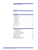
Table of contents Conventions v Symbols . . . . . . . . . . . . . . . . . . . . . . . . . . . . . . . . . . . . . . . . . . . . v Safety notices vii Electrical safety. . . . . . . . . . . . . . . . . . . . . . . . . . . . . . . . . . . . . . vii Disconnect device. . . . . . . . . . . . . . . . . . . . . . . . . . . . . . . . . .ix Laser safety . . . . . . . . . . . . . . . . . . . . . . . . . . . . . . . . . . . . . . . . . x North America . . . . . . . . . . . . . . . . . . . . . . . . . . . . . . . .
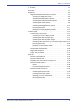
Tab l e o f c on te n ts North America . . . . . . . . . . . . . . . . . . . . . . . . . . . . . . . . . . . xxiii European union . . . . . . . . . . . . . . . . . . . . . . . . . . . . . . . . . xxiv Other countries . . . . . . . . . . . . . . . . . . . . . . . . . . . . . . . . . . xxiv 1. Administrator overview 1-1 Overview. . . . . . . . . . . . . . . . . . . . . . . . . . . . . . . . . . . . . . . . . . 1-1 Logging on as Administrator . . . . . . . . . . . . . . . . . . . . . . . . . . .
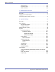
Tab l e of c o n te nts 3. Profiles 3-1 Overview. . . . . . . . . . . . . . . . . . . . . . . . . . . . . . . . . . . . . . . . . . 3-1 Alignment . . . . . . . . . . . . . . . . . . . . . . . . . . . . . . . . . . . . . . . . . 3-2 Alignment Adjustment Profile procedure. . . . . . . . . . . . . . . 3-4 Creating an Alignment profile . . . . . . . . . . . . . . . . . . . . 3-6 Selecting the Registration options . . . . . . . . . . . . . . . . 3-7 Selecting the Perpendicularity options . . . . . . . . . . .
Tab l e o f c on te n ts iv D o c uC o lo r 50 0 0 A d mi n i s t r a t o r G ui d e
Conventions Standardized conventions have been used in this manual to assist you in visually locating and identifying information quickly. Symbols CAUTION: This symbol alerts you to an action that may cause damage to hardware, software, or result in the loss of data. WARNING: Warnings mark alert users to areas of the machine where there is a possibility of personal injury. WARNING: This symbol identifies an area on the machine that is HOT and should not be touched.
Co n v en ti o ns NOTE: This symbol calls your attention to information that is helpful, but not essential to complete a procedure or task. This symbol indicates that there is additional information from another source, such as a web site or manual.
Safety notices This Xerox digital press and the recommended supplies are designed and tested to meet strict safety requirements. These include safety agency approval and compliance to established environmental standards. Please read the following instructions carefully before operating the product, and refer to them as needed to ensure the continued safe operation of your digital press. TIP: The safety testing and performance of this product have been verified using Xerox materials only.
S af et y n o ti c e s WARNING: You may incur a severe electrical shock if the outlet is not grounded correctly. • Do not place the press where people may step or trip on the power cord. Do not place objects on the power cord. • Do not override or disable electrical or mechanical interlocks. • Do not obstruct the ventilation openings. These openings prevent overheating of the machine. WARNING: Never push objects of any kind into slots or openings on this equipment.
S a fe ty n o ti c e s Disconnect device The power cable is the disconnect device for this equipment and is attached to the back of the machine as a plug-in device. To remove all electrical power from the machine, disconnect the power cable from the electrical outlet. WARNING: This product must be connected to a protective earth current.
S af et y n o ti c e s Laser safety North America This product complies with safety standards and is certified as a Class 1 Laser product under the Center for Devices and Radiological Health (CDRH) of the United States Food and Drug Administration (FDA) implemented regulations for laser products. This product complies with FDA 21 CFR 1940.10 and 1040.11 except for deviations pursuant to Laser Notice No. 50, dated July 26, 2001. These regulations apply to laser products marketed in the United States.
S a fe ty n o ti c e s Europe (EU) This product complies with IEC’s safety standard 60825-1 (Edition 1.2) issued August 2001. The equipment complies with laser product performance standards set by governmental, national, and international agencies as a Class 1 Laser Product. It does not emit hazardous radiation as the beam is totally enclosed during all phases of customer operation and maintenance.
S af et y n o ti c e s Safety standards North America This Xerox product is safety certified by Underwriters Laboratories Incorporated to Standards UL60950, third edition (2000), and CSA International CAN/CSA C22.2 No. 60950-00 third edition. Europe (EU) This Xerox product is Safety Certified by NEMKO to publication IEC60950-1 (2001) First Edition. Maintenance safety • Do not attempt any maintenance procedure that is not specifically described in the documentation supplied with your digital press.
S a fe ty n o ti c e s Operational safety Your Xerox equipment and supplies were designed and tested to meet strict safety requirements. These include safety agency examination, approval, and compliance with established environmental standards. Your attention to the following safety guidelines will help ensure the continued safe operation of your digital press: • Use the materials and supplies specifically designed for your digital press.
S af et y n o ti c e s • Do not set up the machine in line with the cold air flow from an air conditioning system. • Do not place containers of coffee or other liquid on the machine. • Do not block or cover the slots and openings on the machine. • Do not attempt to override any electrical or mechanical interlock devices. WARNING: Be careful when working in areas identified with this warning symbol. These areas may be very hot and should not be touched.
Notices Radio frequency emissions FCC in the USA This equipment has been tested and found to comply with the limits for a Class A digital device, pursuant to Part 15 of the Federal Communications Commission (FCC) Rules. These limits are designed to provide reasonable protection against harmful interference when the equipment is operated in a commercial environment.
No ti c e s In Canada (ICES-003) This Class “A” digital apparatus complies with Canadian ICES003. Cet appareil numérique de la classe “A” est conforme á la norme NMB-003 du Canada. Regulatory information for RFID This product generates 13.56 MHz using an Inductive Loop System as a Radio Frequency IDentification system device (RFID). This system is certified in compliance with European Council Directive 99/5/EC and applicable local laws or regulations as applicable.
Notices Certifications in Europe The CE marking that is applied to this product symbolizes Xerox Declaration of Conformity with the following applicable Directives of the European Union as of the dates indicated: January 1, 1995: Council Directive 73/23/EEC amended by Council Directive 93/68/ EEC, approximation of the laws of the member states related to low voltage equipment.
No ti c e s WARNING: In order to allow this equipment to operate in proximity to Industrial, Scientific, and Medical (ISM) equipment, the external radiation from the ISM equipment may have limited or special mitigation measures taken. WARNING: This is a Class A product in a domestic environment. This product may cause radio frequency interference in which case the user may be required to take adequate measures.
Notices 2. Adjusted Compensation Certificates for Veterans of the World Wars. 3. Obligations or Securities of any Foreign Government, Bank, or Corporation. 4. Copyrighted material, unless permission of the copyright owner has been obtained or the reproduction falls within the “fair use” or library reproduction rights provisions of the copyright law. Further information of these provisions may be obtained from the Copyright Office, Library of Congress, Washington, D.C. 20559. Ask for Circular R21. 5.
No ti c e s It’s illegal in Canada Parliament, by statute, has forbidden the reproduction of the following subjects under certain circumstances. Penalties of fines or imprisonment may be imposed on those guilty of making such copies. 1. Current bank notes or current paper money. 2. Obligations or securities of a government or bank. 3. Exchequer bill paper or revenue paper. 4. The public seal of Canada or of a province, or the seal of a public body or authority in Canada, or of a court of law. 5.
Notices Environmental notices for Canada Terra Choice Environmental Services, Inc. of Canada has verified that this Xerox product conforms to all applicable Environmental Choice EcoLogo requirements for minimized impact to the environment. As a participant in the Environmental Choice program, Xerox Corporation has determined that this digital press model meets the Environmental Choice guidelines for energy efficiency.
No ti c e s Product recycling and disposal If you are managing the disposal of your Xerox product, please note that the product contains lead and other materials whose disposal may be regulated due to environmental considerations. The presence of lead is fully consistent with global regulations applicable at the time that the product was placed on the market. North America Xerox operates a worldwide equipment take-back and reuse/ recycle program.
Notices European union Application of this symbol on your equipment is confirmation that you must dispose of this equipment in compliance with agreed national procedures. In accordance with European legislation end-of-life electrical and electronic equipment subject to disposal must be managed within agreed procedures. Prior to disposal, contact your local dealer or Xerox representative for end-of-life take-back information.
No ti c e s xxiv D o c uC o lo r 50 0 0 A d mi n i s t r a t o r G ui d e
1. Administrator overview Overview The Administrator mode allows you to set the default settings for your digital press in order to fit your individual requirements. You can change the settings for a variety of features, such as the language to display on the UI, timers, changing the Administrator password, creating custom paper and alignment profiles, and more. Logging on as Administrator Use the following procedure to enter and exit the Administrator mode: 1.
1. A d m in i s tr a t or ov e r v i e w 3. Select the OK button. The main UI screen now displays additional options and indicates in the upper right that you are in the Administrator mode. NOTE: It is recommended that you change the Administrator password as soon as possible after installing the digital press in order to prevent unauthorized access to the Administrator mode. The procedure for changing the password is on page 2-5 of this book. 4.
1. A d mi n i s tr a to r o v e r v ie w Finishing System Profiles overview If your digital press has an optional, third-party, Digital Finishing Architecture (DFA) device finishing, then the Finishing System Profiles option is available to you. TIP: This feature is available only if you are logged on as the Administrator. Once your system is configured for the optional finishing accessory, the Finishing System Profiles option is accessed from the System pull-down menu on the main UI screen.
1.
2.
2.
2. S y s te m S e tt in g s Fault Details window By default, the UI automatically opens a Details window which provides additional information about the alert, warning, or fault (as shown in the following illustration). However, you can select whether or not you want this window open automatically or to open only when the user clicks on the alert, warning, or fault message in the machine mimic and message area of the UI.
2. S y s t em Se t ti n gs Use the following procedure to choose the default setting for this feature. 1. Select the Logon button from the UI and logon as the Administrator. 2. Select the System Settings button; the System Settings window opens. 3. Select whether or not you want any machine faults to automatically display on the UI when they occur. 4.
2. S y s te m S e tt in g s Change Password Select the Change Password button if you want to change the Administrator password. Use the following procedure to change the Administrator password. 1. Select the Logon button from the main UI window. 2. From the Logon window, enter the Administrator password and select OK. For security reasons, only asterisks are displayed on the screen. NOTE: The digital press arrives from the factory with a default Administrator password of five ones (11111).
2. S y s t em Se t ti n gs 3. Select the System Settings button. 4. From the System Settings window, select the Change Password button from the User Interface tab. The Change Password window opens.
2. S y s te m S e tt in g s TIP: Use numbers only for creating your new password. Alpha characters (letters and other characters, such as !*& are not allowed). A maximum of twelve numbers can be entered for your password. 5. From the Change Password window, enter: a. The old (current) password b. The new password c. Reenter the new password in the Confirm New Password area d. Select OK NOTE: For security reasons, only asterisks are displayed on the screen. 6.
2. S y s t em Se t ti n gs Setting the Date & Time Use this feature to set the date and time for the system. The date and time is displayed on the Machine Details screen on both the Installed Software and Error Log screens. 1. From the System Settings window, select the Date/Time tab. 2. 3. Select the Date Format you wish to use. 4. 5. Select the Time Format you wish to use. Use the up or down arrow buttons to enter the correct year, month, and day.
2. S y s te m S e tt in g s System Use this feature to change the factory default settings for the following: • Productivity Mode • Power Saver (Enter and Exit options) • Auto Resume • Job Spacing • Auto Logoff The System feature also allows you to enter NVM Read/Write values when using specialized media. This is discussed in more detail on page 2-19.
2. S y s t em Se t ti n gs Productivity Setting The productivity of the digital press relates to the continuous speed of the media output as measured in prints per minute (ppm). The continuous speed is dependent on paper size, paper weight, and fuser temperature. Use this setting to optimize the throughput speed for the type of paper you run most frequently.
2. S y s te m S e tt in g s Productivity charts The following productivity charts lists the various paper weights and sizes and their related print speeds for 1 Sided and 2 Sided output. Each chart outlines the print speed parameters for both productivity settings. Single Paper Weight Single Paper Weight Mode Paper Weight 60 - 220 g/m2 221 - 300 g/m2 Transparency Paper Size (Feed direction length) [mm] Print Speed (prints per minute - ppm) Min. Max 1 Sided 2 Sided 182.0 216.0 50 25 216.
2. S y s t em Se t ti n gs Mixed Paper Weight Mixed Paper Weight Mode Paper Weight 60 - 135 g/m2 136 - 186 g/m2 187 - 220 g/m2 221 - 300 g/m2 Transparency Paper Size (Feed direction length) [mm] Print Speed Min. Max 1 Sided 2 Sided 182.0 216.0 50 25 216.1 297.0 33.3 16.7 297.1 458.0 25 12.5 458.1 488.0 20 10 182.0 216.0 33.3 16.7 216.1 297.0 25 12.5 297.1 458.0 16.7 8.3 458.1 488.0 12.5 6.3 182.0 216.0 33.3 16.7 216.1 280.0 20 10 280.1 432.0 16.7 8.
2. S y s te m S e tt in g s Power Saver Use this feature to set the time that elapses until the digital press and System PC enter a reduced power consumption mode. The timers are activated when all print jobs have been completed and there are no jobs in the job queue. The digital press and/or System PC exits the Power Saver mode when a job is sent to be printed or the UI on the System PC is activated.
2. S y s t em Se t ti n gs 2. Use the up or down arrow buttons to change the time for each of the power saver features: • System PC & Print Engine • Print Engine Only • Print Engine Power Only If No PC Communication For The range available is 1-240 minutes. NOTE: The system default time is sixty minutes. 3. Select OK to save your changes and close the System Settings window.
2. S y s te m S e tt in g s Fault Clearance Use the Auto Resume After Fault Clearance feature to restart a job automatically after a fault is cleared and a job received over the network is waiting for user instruction. 1. From the System tab of the System Settings window, select the checkbox to the left of Fault Clearance. 2. Use the up or down arrow buttons to change the time. The range available is 1-10 minutes. NOTE: The system default time is two minutes. 3.
2. S y s t em Se t ti n gs Pause Use the Auto Resume After Pause feature to restart a job automatically after the Pause button is selected on the UI and the job is waiting for user instruction. 1. From the System tab of the System Settings window, select the checkbox to the left of Pause. 2. Use the up or down arrow buttons to change the time. The range available is 1-10 minutes. NOTE: The system default time is two minutes. 3.
2. S y s te m S e tt in g s Job Spacing Use the Job Spacing feature when there are multiple jobs queued and you would like to allow seven seconds to unload prints from a finishing device before the next job starts printing. 1. From the System tab of the System Settings window, select the checkbox to the left of Job Spacing. Seven seconds is the standard and only time for this option. 2. Select OK to save your changes and close the System Settings window.
2. S y s t em Se t ti n gs Auto Logoff Use the Auto Logoff feature to have the digital press automatically return to the printing mode when no action is taken from any of the Administrator functions after the set amount of time. 1. From the System tab of the System Settings window, select the checkbox to the left of Auto Logoff. 2. Use the up or down arrow buttons to change the time. The range available is 10-60 minutes. NOTE: The system default time is ten minutes. 3.
2. S y s te m S e tt in g s NVM Read/Write Your Xerox service representative uses this feature to change certain system settings. It also may occasionally be used by system administrators. Under most conditions, this feature is not used by system administrators; however, there are limited circumstances under which this feature is used.
2. S y s t em Se t ti n gs To switch on a feature, perform the following: 1. From the System tab on the System Setting window, select the NVM Read/Write button. The NVM Read/Write window opens. 2. Enter the desired Chain Link Number: • The Chain Link Number for Special Media Setting for Drilled Papers is 700 545. • The Chain Link Number for Special Media Setting for LEF Tab Stock is 700 546. • The Chain Link Number for Carbonless Media Enablement is 700-920.
2. S y s te m S e tt in g s a. Using the numbers on the keyboard, enter the Chain Number (the following example uses 123 as the Chain number). b. Press the Tab button on the keyboard to advance to the Link field. c. Enter the Link number (the following example uses 123 as the Link number). d. Select the Next button.
2. S y s t em Se t ti n gs 3. Using the keyboard, enter the New Value (the following example uses 234 as the New Value number). TIP: To switch on a feature, enter the appropriate value from the keyboard: 2- 2 2 • For Special Media Setting for Drilled Papers, enter 0 for the New Value. • For Special Media Setting for LEF Tab Stock, enter 1 for the New Value. • For Carbonless Media, enter 1 for the New Value. 4. Select the Apply button.
2. S y s te m S e tt in g s TIP: After running your print job, reenter Administrator mode, System Settings, NVM Read/Write, and switch off the feature that is currently on. Follow the steps outlined in this procedure and use these settings for the New Value number: • To switch off the Special Media Setting for Drilled Papers, enter 1000. • To switch off the Special Media Setting for LEF Tab Stock, enter 0. • To switch off the Carbonless Media, enter 0.
2. S y s t em Se t ti n gs 2- 2 4 1. From the System Setting window, select the Tray Options tab. 2. Select either the Enable or Disable button for the Auto Tray Switching option. 3. Select either the Enable or Disable button for the Auto Paper Selection option. 4. To instruct the digital press to bypass (ignore) one or more of the paper trays, select the checkbox to the left of the desired paper pray in the Do Not Include area. 5. Select OK to close the System Settings window.
2. S y s te m S e tt in g s Paper Tray Assist Blowers help control the environmental conditions in the paper trays to ensure optimum print capability: • Each paper tray has two blowers and two fans. The blowers are located in the front of each tray, while the two fans are located on the right-side of the tray. • The lead edge blower is on at all times and produces heated air if one of the following selections are made: Coated paper, Transparencies, or Plain paper 106 g/m2 or heavier.
2. S y s t em Se t ti n gs If you adjust the blowers on the tray to accommodate a particular type of paper (for example, thin or thick), you want to make adjustments on the Tray Options window from the Administrator mode. This will provide optimal output quality of your prints. To make these adjustments, use the following procedure: 1. From the System Setting window, select the Tray Options tab. 2. 3. Select either the desired tray.
2. S y s te m S e tt in g s 4. • Always On (Thin Paper): With this option, the paper tray blowers are not automatically controlled, but the are always switched on. This mode is also reserved for special media. • Always On (Thick Paper): With this option, the paper tray blowers are not automatically controlled, but they are always switched on. This mode is reserved for special media. Select OK to close the System Settings window.
2. S y s t em Se t ti n gs Tray Priority Select the priority order for each paper tray. If the Auto Tray Switching feature is enabled and each paper tray contains the same paper size and weight, the digital press feeds paper from the tray set at Priority 1. If there is no paper in the Priority 1 tray, the Priority 2 tray is automatically selected and so on. Use the following procedure to set the priority for each paper tray. 2- 2 8 1. From the System Setting window, select the Tray Options tab. 2. 3.
3. Profiles Overview Profiles allows you to create and customize profiles for Custom Paper, Alignment, and Decurler. These profiles are used at the point of need for specialized print jobs which may require different types of media, such as lightweight or heavy stock. Using a customized profile can provide optimum image and output quality. NOTE: The Profiles features can only be accessed from the Administrator mode.
3. P r o fi l e s Alignment When printing duplex jobs and using different media types (including paper type, weight, and coating/uncoating), the output may require specific handling by the digital press as it is moving through the paper path. With certain media types and duplex jobs, the images on Side 1 and/or Side 2 may be misregistered, skewed, perpendicularly misaligned, or stretched.
3 . P r o fi l e s When creating Alignment Profiles for Side 1 and/or Side 2 prints, be aware of the following: • Side 1/Side 2 images may be misregistered because the paper is not the exact same size. It may vary slightly, with differences of plus or minus 1mm, causing the image to be misregistered. To reduce the possibility of size differences, it is recommended that you use paper from the same lot when running duplex jobs.
3. P r o fi l e s Alignment Adjustment Profile procedure Use the following procedure to create/modify an Alignment Profile for adjusting Side 1/Side 2 image output. NOTE: If you require a Custom Paper Profile associated with this Alignment Profile, you can set the Custom Paper Profile information either now or after you create the Alignment Profile. 3- 4 1. Select the Logon button from the main UI window. 2. From the Logon window, enter the Administrator password and select OK. 3.
3 . P r o fi l e s 4. From the Profiles window, select the Alignment tab. 5. To create a new alignment procedure, select a undefined profile. If you are editing an existing profile, go to Editing an existing Alignment profile. 6. Next: Creating an Alignment profile.
3. P r o fi l e s Creating an Alignment profile 3- 6 7. Click the Edit button; the Alignment Profile Properties window opens. 8. Type a name for this profile (the example in this procedure uses the name “AlignmentProfile2”). 9. Next: Selecting the Registration options.
3 . P r o fi l e s Selecting the Registration options 10. Make the desired selections to the Registration option. • Lead Registration: Use this feature to adjust the lead edge of the image for Side 1 and/or Side 2 registration. • Side Registration: Use this feature to adjust the side edge of the image for Side 1 and/or Side 2 registration. The factory default setting is zero (0). These arrows indicate the paper feed direction Use the up/down arrow buttons to make the desired selections..
3. P r o fi l e s Selecting the Perpendicularity options 12. Make the desired selections to the Perpendicularity option. Use this feature to adjust the image digitally on the drum so that it will align with the paper for both Side 1 and Side 2. The factory default is zero (0). These arrows indicate the paper feed direction Use these to make the desired selections. As you click on the up or down arrows, the illustration moves indicating the direction that the image will move on the paper. 13.
3 . P r o fi l e s Selecting the Skew options 14. Make the desired selections to the Skew option. Use this feature to adjust the paper so that the image for Side 1 and/ or Side 2 are not skewed but aligned with each other. The factory default is zero (0). These arrows indicate the paper feed direction Use these to make the desired selections. As you click on the up or down arrows, the illustration moves indicating the direction that the image will move on the paper. 15.
3. P r o fi l e s Selecting the Magnification options 16. Make the desired selection to the Magnification option. Use this feature to correct for image stretch from Side 1 to Side 2. The image may be enlarged or reduced as necessary. The factory default is zero (0). These arrows indicate the paper feed direction Use these to make the desired selections. As you click on the up or down arrows, the illustration moves indicating the direction that the image will move on the paper.
3 . P r o fi l e s Running test prints 18. Select the Test Print button; a new window opens. a. Select the 2 Sided button. NOTE: If you want to check the registration for 1 Sided prints only, select the 1 Sided button. b. Select 10 test prints by clicking the Up arrow button to change the number of test prints generated. c. Select the desired paper tray from the pull-down list. d. If necessary, select the Tray Properties button and make any desired settings.
3. P r o fi l e s e. Select Start. The UI displays this message after the test prints are printed: f. Retrieve your prints. g. Discard the first few prints, as inconsistency tends to be greater with these images. 19. Evaluate the test prints by holding your 2 Sided output at eye level near a light source. This will allow you to see the registration marks for both Side 1 and Side 2 of the output. a.
3 . P r o fi l e s Editing an existing Alignment profile 21. If you are editing an existing Alignment profile: a. From the Profiles window, Alignment tab, select the desired profile. b. Click the Edit button. c. Repeat this procedure starting at Selecting the Registration options.
3. P r o fi l e s Custom Paper Different media (including paper type, weight, and coating/ uncoating) may require specific handling by the digital press as it is moving through the paper path. For example, some media types may skew or curl as they progress through the printing path of the digital press. This may occur on frequently-run jobs and/or jobs with a high volume output.
3 . P r o fi l e s Custom Paper procedure Use the following procedure for creating/modifying a Custom Paper Profile. 1. From the Profiles window, select the Custom Paper tab. 2. To create a new custom paper procedure, select a undefined profile. If you are editing an existing profile, go to Editing a Custom Paper profile. 3. Next: Creating an Custom Paper profile.
3. P r o fi l e s Creating an Custom Paper profile 3- 1 6 4. Click the Edit button; the Custom Paper Profile Properties window opens. 5. Type a name for this profile (the example in this procedure uses the name “Custom Paper1”). 6. Next: Selecting the desired paper type.
3 . P r o fi l e s Selecting the desired paper type 7. Select the desired paper Type from the pull-down menu. TIP: The paper type does not have to match the actual type of paper you are loading in the tray. When creating a Custom Paper Profile, select a paper type that is rarely or never used as your standard paper types. This ensures that when running commonly used paper types, the digital press does not load a Custom Paper Profile for those types. 8. Next: Selecting the desired paper weight.
3. P r o fi l e s Selecting the desired paper weight 3- 1 8 9. Select the desired paper Weight from the pull-down menu. 10. Next: Selecting other options for your Custom Paper profile.
3 . P r o fi l e s Selecting other options for your Custom Paper profile 11. If required, select a Decurler Profile from the pull-down menu. TIP: The default setting is System Default. It is recommended that you leave this option at its default setting until you run test prints and evaluate the output of the prints. Test Print is discussed in more detail in Running test prints. NOTE: Use the Decurler feature in order to compensate for paper curl in your output prints.
3. P r o fi l e s 12. If required, select an Alignment Profile from the pull-down menu. TIP: The default setting is Use Tray Properties. It is recommended that you leave this option at its default setting until you run test prints and evaluate the output of the prints. Test Print is discussed in more detail in Running test prints.
3 . P r o fi l e s NOTE: If you select a specific Alignment Profile, the Profiles Properties button becomes accessible. By clicking on this button, the UI opens the Alignment Profile window for the selected profile, and you can edit that Alignment Profile if necessary. NOTE: For Alignment information, refer to page 3-2. 13. If required, choose 2nd Bias Transfer Roll settings for Sides 1 and 2.
3. P r o fi l e s TIP: The default setting for both Sides 1 and 2 is 100%. It is recommended that you leave this option at its default setting until you run test prints and evaluate the output of the prints. Test Print is discussed in more detail in Running test prints. NOTE: Refer to page 3-26 for information on the 2nd Bias Transfer Belt. 14. If required, choose an Aligner Roll Pressure setting. TIP: The default setting is 0.
3 . P r o fi l e s 15. If required, choose a Paper Tray Air Assist option from the pull-down menu. TIP: The default setting Use Tray Option. It is recommended that you leave this option at its default setting until you run test prints and evaluate the output of the prints. Test Print is discussed in more detail in Running test prints. NOTE: Refer to page 3-31 for information on the Paper Tray Air Assist. 16. 17. Load your custom paper in the desired paper tray. 18. Next: Running test prints.
3. P r o fi l e s Running test prints 19. Select the Test Print button; a new window opens. a. Select the 2 Sided button. NOTE: If you want to check the registration for 1 Sided prints only, select the 1 Sided button. b. Select 10 test prints by clicking the Up arrow button to change the number of test prints generated. c. Select the desired paper tray from the pull-down list. d. If necessary, select the Tray Properties button and make any desired settings. e. Select Start.
3 . P r o fi l e s 20. Evaluate the test prints by holding your 2 Sided output at eye level near a light source. a. If you determine that further custom paper adjustments are required, repeat this procedure starting at Selecting the desired paper type. TIP: You may need to repeat this procedure numerous times until you achieve acceptable output prints. b. If the printed output for both Sides 1 and 2 is acceptable, select OK to save and close the Profiles window.
3. P r o fi l e s Second Bias Transfer Belt The Second Bias Transfer Belt is where the image is transferred from the belt to the paper. The Second Bias Transfer Belt feature is normally used with heavier weight paper, such as 220 g/m2 and greater, 10 pt, or 12 pt, which are just three examples; however there are times when it is also used with lighter weight paper as well. When using either heavier or lighter weight paper, you may want or need to adjust Side 1 for all 1-sided jobs.
3 . P r o fi l e s 3. Use the 2nd Bias Transfer Belt feature when your: a. Prints may have mottle, which is uneven spotty toner coverage that occurs when printing large, solid areas of flat color.
3. P r o fi l e s If mottle exists and it is heavy weight paper, increase one or both of the 2nd BTB values. If mottle exists and it is light weight paper, increase one or both of the 2nd BTB values. Evaluate the image quality. If the image quality is equal to or worse than the 100% default setting, decrease one or both of the 2nd BTB values until a satisfactory image quality is obtained.
3 . P r o fi l e s b. Prints have a color shift where the colors are much different than what you desire. This test pattern represents an output with the desired colors. This test pattern represents an output with a shift in colors, and thereby an undesired output. If mottle color shift exists, increase one or both of the 2nd BTB values.
3. P r o fi l e s Aligner Roll Pressure Use this feature with paper types that slip and skew or have damaged edges. Examples: • Some coated paper types slip and skew, thereby misregistering the image on the output prints. In this case, you may want to increase the roll pressure in order to compensate for the slippage and skewing. • Some light-weight papers may have too much roll pressure applied to them, thereby causing edge damage to the output prints.
3 . P r o fi l e s Paper Tray Air Assist Use this feature to switch on or switch off the fans in a paper tray in order to eliminate misfeeds, paper jams, or other possible tray feeding problems. You can also select System Default or Use Tray Option if you want the digital press to decide whether or not to switch on or off the fans for a paper tray. NOTE: The default setting is Use Tray Option. Refer to page 2-26 of this book for information on each one of the Paper Tray Air Assist settings.
3. P r o fi l e s Decurler TIP: Please read all the Decurler information before using the Decurler Profile procedure. IMPORTANT! If you notice that output prints have too much curl, first try flipping over the stack of paper in the paper tray being used. You can also try running the job from a different tray. If curl is still a problem, use one of the Decurler A-D Settings; refer to the Decurler Settings A-D table on page 3-34 for your market area.
3 .
3. P r o fi l e s Decurler settings A-D The default Decurler settings for Type A through Type D are shown in the following table. These settings are automatically selected by the digital press.
3 . P r o fi l e s Decurler A-D procedure If paper curl is interfering with digital press performance, begin by selecting an alternate Decurler Paper Type A through Type D setting 1. Select one of these Decurler A-D settings from the Tray Properties window. 2. Run the same print job again, and retrieve the output from the exit area of the digital press. 3. Check the output for curl. a. If the curl is eliminated, you are finished. Continue running your prints using the specific Decurler A-D setting.
3. P r o fi l e s Evaluate your print output for paper curl Before using a specific Decurler Profile, evaluate your output for paper curl and whether or not you need to use a Decurler Profile by performing the following steps. 1. Determine if Xerox has tested your paper type and weight by going to the www.xerox.com web site and referring to the latest Recommended Materials List (RML) for your digital press. 2.
3 . P r o fi l e s 5. Select the pages from your original print job that represent the extremes in curl (this usually indicates the print with the highest area of toner coverage). 6. 7. Lay the curled output page on a flat surface. Measure the height of the sheet, in millimeters (mm), at the four corners of the sheet. Measuring the curl of an upward sheet Measuring the curl of a downward sheet a. Add the four values, then divide by four to get an average. b.
3. P r o fi l e s Decurler Profile options Before you can create or use a Decurler Profile, you need to understand the function of the Decurler Profile options. The following illustration shows the Decurler Profile Properties window. 3 5 4 1 2 6 NOTE: Items 1-6 are discussed in the sections entitled Name and Downward/Upward Values. 3- 3 8 1 Name: Refers to the Productivity Mode setting.
3 . P r o fi l e s 6 Percentage value: The number entered here represents the percentage of toner area coverage on the originals. NOTE: Print jobs that consist of multiple pages usually have a variety of toner area coverage; therefore a range of toner area coverage is provided by the machine. Usually the page (or pages) that create the largest amount of curl will correlate with the largest amount of toner coverage.
3. P r o fi l e s Downward/Upward Values The Downward and Upward values control a mechanism in the digital press that compensates for the curl formed in the fusing process; this is done by inducing an equal but opposite curl in the paper. It is similar to passing a sheet over a sharp radius, and thereby producing a curl in the direction of the radius.
3 . P r o fi l e s • The output print in the output area is curled upwards and was measured with a curl average of 10 mm (refer to Evaluate your print output for paper curl). • Using the 1-Sided Face Up row, as shown below, enter the known values into the table. • Average curl is 10 mm upward and average toner area coverage is 5%. Therefore, select Upward and enter 5% for the 10 mm column. • Enter any higher number for the 6 mm (such as 6%) and the 2 mm (such as 7%).
3. P r o fi l e s Decurler Profile procedure IMPORTANT! Before using this procedure, use a Decurler A-D setting to eliminate the curl in our print output; refer to page 334. If a Decurler A-D setting is unsuccessful in eliminating your curl, evaluate the curl on the output prints (page 3-36). Once you have measured and recorded the curl on your output, then you can perform this procedure. 1. Load a specific Paper Tray with the paper you wish to use for a job.
3 . P r o fi l e s 4. Check the output for curl. a. If the curl is eliminated, you are finished. Continue running your prints using the specific Decurler A-D setting. b. If the curl is still persistent, try another Decurler Paper Type (A-D). 5. If the curl continues after each Decurler Paper Type A-D setting is tried, continue to the next step. 6. 7. Logon on Administrator and select the Profiles button. From the Profiles window, select the Decurler tab.
3. P r o fi l e s 8. To create a new decurler profile, select a undefined profile and click Edit. The Decurler Profile Properties window opens. 3- 4 4 9. Type a name for this profile (the example in this procedure uses the name “DecurlerProfile1”). 10. Measure and record the curl amount of the output print which contains the most curl. Refer to Evaluate your print output for paper curl.
3 . P r o fi l e s 11. Enter your curl calculations in the Downward/Upward tables. 12. Select OK to save and close the profile. NOTE: If the values entered in the Downward and Upward tables have conflicting values (not in ascending or descending order across an entire row), an error message is displayed and you must be reenter the values until they do not conflict. 13. Close the Profiles window.
3. P r o fi l e s 14. From the Tray Properties window, select the Decurler Profile that you just created/edited (for example, DecurlerProfile1). 15. Select the pages from your original print job that represent the extremes in curl. 16. 17. Enter a print quantity of 20-25 and print these pages. Retrieve your output and compare the paper curl condition of the original stack with the paper curl of the new stack. a.
3 . P r o fi l e s TIP: You may need to repeat this procedure numerous times until you achieve acceptable output prints. 18. If you are editing an existing Decurler profile: a. From the Profiles window, Decurler tab, select the desired profile. b. Click the Edit button. c. Repeat this procedure starting at Step 6. 19. If you are not successful in reducing the curl, call your Xerox service representative.
3.