Xerox DocuPrint 96/DocuPrint 96MX Laser Printing System Forms Creation Guide April 1998 721P85630
Xerox Corporation 701 S. Aviation Boulevard El Segundo, CA 90245 ©1998 by Xerox Corporation. All rights reserved. Copyright protection claimed includes all forms and matters of copyrightable material and information now allowed by statutory or judicial law or hereinafter granted, including without limitation, material generated from the software programs which are displayed on the screen, such as icons, screen displays, looks, etc. Printed in the United States of America.
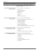
Related publications The Xerox DocuPrint 96/DocuPrint 96MX Laser Printing System Forms Creation Guide is part of the eight manual reference set for your laser printing system. The entire reference set is listed in the table below. Several other related documents are also listed for your convenience.
iv XEROX DOCUPRINT 96/DOCUPRINT 96MX LPS FORMS CREATION GUIDE
Table of Contents Related publications iii Notice iii Introduction 1. 2.
TABLE OF CONTENTS Specifying TAB as a form 3-8 LANDSCAPE/PORTRAIT command 3-9 GRID command 3-10 FONT command 3-15 Description commands 3-16 LINE command Types of lines 4.
TABLE OF CONTENTS Local density and page setup errors 5-6 Summary 5-7 Using boxes 5-8 Text in boxes 5-8 Locating the closest box 5-9 Shading 5-12 Sections 5-13 Rounding measurements 5-14 Converting other unit values to dots 5-14 Rounding variable data 5-15 Suggested coding techniques Converting preprinted forms 5-16 Designing new forms 5-16 Recommended coding sequence 5-16 Syntax ambiguities 6.
Index viii INDEX-1 XEROX DOCUPRINT 96/DOCUPRINT 96MX LPS FORMS CREATION GUIDE
Introduction The DocuPrint 96/DocuPrint 96MX Laser Printing System Forms Creation Guide is intended for forms designers who have a basic knowledge of the DocuPrint 96/DocuPrint 96MX Laser Printing System (LPS). You may have received on-site training, or you may have attended a Xerox FDL training course. The forms designer’s tasks consist of writing FDL commands to produce electronic forms.
INTRODUCTION Xerox DocuPrint 96/DocuPrint 96MX Laser Printing System document set The Xerox DocuPrint 96/DocuPrint 96MX LPS document set includes the following: Xerox DocuPrint 96/DocuPrint 96MX LPS Operator Guide Xerox DocuPrint 96/DocuPrint 96MX LPS PDL Reference Xerox DocuPrint 96/DocuPrint 96MX LPS System Generation Guide Xerox DocuPrint 96/DocuPrint 96MX LPS Operations Reference x This reference contains the following information: • • • • • • • System overview Paper facts and procedures Operati
INTRODUCTION Xerox DocuPrint 96/DocuPrint 96MX LPS Forms Creation Guide This reference contains the following information: • • • • Basic concepts for creating forms Coding and compiling for LPS Forms Description Language Sample form setup command sets Tips for successful forms creation Xerox DocuPrint 96/DocuPrint 96MX LPS Operator Command Summary Card This reference provides a quick reference of commonly-used commands.
INTRODUCTION What this guide contains The DocuPrint 96 Laser Printing System Forms Creation Guide shows how to create electronic forms by describing them in words and numbers. FDL is not complicated; it requires performing a few dimensional measurements and learning some easy-to-follow rules. The guide is divided into six chapters and six appendices as follows: Chapter 1: Overview.
INTRODUCTION Conventions used in this guide This guide uses the following conventions: <> Angle brackets are used for keys on the keyboard. { } Braces indicate that one of the items stacked inside must be entered. ... [ ] | bold italics TERMINAL FONT underline UPPERCASE Ellipses indicate that you can repeat a parameter or list a series of parameters. Square brackets are used for optional command characters. Vertical bars are used to separate parameters in a series. The vertical bar stands for ”or.
INTRODUCTION xiv XEROX DOCUPRINT 96/DOCUPRINT 96MX LPS FORMS CREATION GUIDE
1. 1Overview The laser printing system (LPS) provides the capability to create electronic forms tailored to meet your individual requirements. You create electronic forms using Forms Description Language (FDL). This simple-to-learn, easy-to-use language enables you to design and alter forms in minutes. FDL eliminates the need for preprinted forms and the expense of forms obsolescence. It also eliminates the delays associated with stocking forms and overlays.
OVERVIEW Laser printing technology Before you learn about the actual forms creation process, an introduction to the printing system will be helpful. Xerox laser printing systems are sophisticated nonimpact printers that use a combination of laser, digital, and xerographic technologies for their imaging and printing processes. These advanced technologies allow the LPS to avoid optical constraints such as form overlays and limited character fonts.
OVERVIEW Fonts A set of standard LPS fonts are provided free of charge at installation time. (Font is a publishing term referring to a set of characters with the same type style, type size, and orientation.) Note: Additional fonts, whether standard or custom designed, may be special ordered from the Xerox Font Center or Xerox Limited. You can also order digitized logos and signatures. Refer to your DocuPrint 96/DocuPrint 96MX LPS Installation Planning Guide for information on ordering fonts.
OVERVIEW 1-4 XEROX DOCUPRINT 96/DOCUPRINT 96MX LPS FORMS CREATION GUIDE
2. 2Basic concepts Certain basic concepts are required to understand the forms creation process on laser printing systems. These involve the size, shape, and location of the overall image on the page of a document, the orientation of the text or graphics on the page, the size and style of the characters to be used, and the type of data to be entered.
BASIC CONCEPTS Fonts Fonts are character sets, each having a unique type style, type size, and orientation. Fixed and proportional spacing Fixed and proportionally spaced fonts are available for use on laser printing systems. Each character occupies an area on the form called a character cell. With fixed fonts, all character cells in the set are the same width. With proportional fonts, character cells vary in width, as shown in figure 2-2. Figure 2-2.
BASIC CONCEPTS Figure 2-4. Font orientation Note that even though type style and size are the same, four different fonts are used, each with a unique orientation. The inverse portrait font could be used for certain types of titles or labels on a landscape form. Conversely, the inverse landscape font could be used for titles on a portrait form.
BASIC CONCEPTS Page frames A page frame is a set of boundaries associated with a page as a unit of printing or imaging. Three page frames are defined in this guide: • • • Physical page System page Virtual page Physical page The paper on which a form is printed is the “physical page.” The default paper size used on an LPS is defined during system generation (sysgen). The following paper sizes may be specified: • • • • • • • • • • • • • • • • 8.5 by 11 inches (USLETTER, 216 by 279 mm) 8.
BASIC CONCEPTS System page The maximum area in which graphics and text can be imaged is called the “system page.” Edgemarking To accommodate edgemarking, which is the placement of marks along the edge of the physical page, the system page must be larger than the physical page. The edgemarking capability is limited because the system page boundaries correspond to the physical page on at least two edges for all paper sizes.
BASIC CONCEPTS Form origin All forms data described by FDL commands is positioned relative to a point called the “form origin.” This point is offset from the virtual page corner by horizontal and vertical displacement values, which you specify using the GRID command. If none are specified, standard default values are used to establish the form origin.
BASIC CONCEPTS Table 2-1.
BASIC CONCEPTS Grids The location of a form element on a page is specified in terms of its horizontal and vertical displacement from the form origin. The units of measurement used to define this displacement can be the following: • • • • Linear units—inches or centimeters Dots—300 per inch Xdots—600 per inch Cpi and lpi—(characters per inch horizontally and lines per inch vertically). x and y coordinate The y coordinate describes the vertical position on a grid.
BASIC CONCEPTS If you are measuring the grid in cpi and lpi units, the origin of the “A” character cell is located two lines down and one character width to the right of the form origin. At 10 cpi and 6 lpi, the “A” is .33 inch down from the form origin and .10 inch to the right. Negative coordinates Negative x and y values also may be used to place form elements above and or to the left of the form origin, as long as the values are within system page boundaries.
BASIC CONCEPTS Predefined formats A set of predefined print description entries or formats, having standard format specifications, are provided on the operating system software (OSS) tapes. You may use these standard print formats or define your own to suit your specific needs. These standard formats provide commonly used impact printer conversion formats for use with specific page sizes and orientations. Use the Xerox Design Ruler to assist you in measuring character and line spacing.
BASIC CONCEPTS Table 2-2 lists the standard LPS print formats. Table 2-2. Standard LPS print formats cpi Approx. point size Begin Page size and values (y,x) orientation* Default font ID 8.1 13.6 9 11 by 8.5 in (.18,.66) L0112B 150 8.1 15.0 9 11 by 8.5 in (.18,.50) L0212A 88 132 10.7 13.6 7 11 by 8.5 in (.14,.66) L0312A FMT4 88 150 10.7 15.0 7 11 by 8.5 in (.14,.50) L0412A FMT5 49 100 6.0 10.0 12 11 by 8.5 in (.17,.50) L0512A FMT6 80 100 8.1 13.6 9 8.
BASIC CONCEPTS Data types Two types of data are used in LPS forms creating and printing: • • Variable data Forms data The term “variable data” generally refers to computer produced information that the LPS merges with a form. Typically this data varies from page to page. The term “forms data” refers to information that is used to print the form, such as lines between columns and rows, boxes, and shading.
3. 3Forms description language This chapter describes the function and use of each forms description language (FDL) command in generating a form electronically. FDL command overview FDL is a set of keyword commands that you can use to generate an electronic form. To do this, you create a source file of FDL commands that describes the characteristics of your form. The form can contain a variety of fonts, logos and graphics, and it can be merged with variable data during printing.
FORMS DESCRIPTION LANGUAGE Command summary The following commands are available for creating a form: FORM /RESOLUTION PAPER LANDSCAPE/PORTRAIT Identifies the name of a form in the forms library and the resolution at which the form should be compiled for printing. Identifies the paper size for which the form is designed. Specifies page orientation and virtual page size. GRID Specifies the grid units used in describing the form and the origin of the form relative to the virtual page origin.
FORMS DESCRIPTION LANGUAGE Command format The following is true for each FDL command: • The command consists of a command identifier and various parameters and keywords associated with the function. • • • Spaces or commas separate keywords and parameters. • Multiple commands may appear in one record if separated by a semicolon. • Commands can be continued on multiple lines before ending with a semicolon, with the exception of the LINE and BOX command.
FORMS DESCRIPTION LANGUAGE Steps to creating a form There are three basic steps required to produce an electronic form: 1. Initiate an editing session. 2. Enter the FDL commands. 3. Compile and print the form. Initiating an editing session The editor utility is used to create and modify your forms source library (FSL) source files. If you use your host editor utility, follow the instructions provided in your host documentation.
FORMS DESCRIPTION LANGUAGE Setup commands Before entering commands to describe a form, enter the setup commands to specify the following: • • • • • FORM command PAPER command LANDSCAPE/PORTRAIT command GRID command FONT command Of the setup commands, only the FORM command is always required. The others are optional. (If they are not defined, the defaults are used.) The FONT command is also required if text is to be included on the form. FORM command The FORM command defines the name of the form.
FORMS DESCRIPTION LANGUAGE PAPER command This command identifies the paper size for which the form is designed. It is an optional command that enables you to select a paper size that is different than the sysgen-defined paper size. Specifying paper size The format of the command for specifying standard paper sizes is as follows: PAPER [SIZE] [IS] USLETTER ; A4 USLEGAL A3 B4 x BY y OPTION DESCRIPTION USLETTER 8.5 by 11 inches (216 by 279 mm) A4 8.27 by 11.69 inches (210 by 279 mm) USLEGAL 8.
FORMS DESCRIPTION LANGUAGE Using B4 paper size When B4 size paper is specified in centimeters, the value should be rounded off to 25.71 CM. This is only necessary when your GRID statement is GRID [UNIT] [IS] INCHES. When no paper size is specified When there is no PAPER [SIZE] command specified in the FSL, the DocuPrint 96/DocuPrint 96MX uses the sysgened paper size as the default. The sysgen process does not check for the minimum nor the maximum paper size.
FORMS DESCRIPTION LANGUAGE Specifying TAB as a form To define a form to be used as a tab, specify the following: PAPER [SIZE] [IS] 9 BY 11; Refer to your DocuPrint 96/DocuPrint 96MX LPS PDL Reference for a detailed explanation of the Ordered and Tab Stock feature.
FORMS DESCRIPTION LANGUAGE LANDSCAPE/PORTRAIT command Specifying page orientation and virtual page size LANDSCAPE PORTRAIT The LANDSCAPE/PORTRAIT command tells the system the orientation of the form. A LANDSCAPE form is oriented horizontally (like most paintings or photographs of landscape scenes). A PORTRAIT form is oriented vertically (like most portraits of people). The LANDSCAPE/PORTRAIT command also specifies the virtual page size and origin of the form.
FORMS DESCRIPTION LANGUAGE GRID command Specifying grid unit size and form origin The GRID command tells the system how far apart to space the horizontal and vertical grid lines. This command also specifies the location of the form origin with respect to the virtual page origin. All FDL commands create and place form elements (lines, boxes, and so forth) relative to the form origin. The format of the GRID command is as follows: Example: GRID IS 1 INCH; format-id Name of a predefined format.
FORMS DESCRIPTION LANGUAGE • The GRID command may specify the name of a format, which automatically provides page orientation, form origin, and grid unit dimensions. (Refer to table 2-1.) All predefined formats specify the grid units in lines and characters per inch. The predefined format’s BEGIN values are used to place the form origin, unless overridden by an ORIGIN parameter.
FORMS DESCRIPTION LANGUAGE Example 2 LANDSCAPE; GRID [UNIT] [IS] FMT1 ORIGIN 1 INCH 1 INCH; Figure 3-2 shows a form with the origin offset one inch from the virtual page origin. Figure 3-2. Form with origin offset one inch from virtual page origin In example 2, the ORIGIN parameter in the GRID command specifies a form origin that is offset from the virtual page origin by one inch vertically and one inch horizontally. Grid unit dimensions are set by FMT1.
FORMS DESCRIPTION LANGUAGE Example 4 LANDSCAPE PAGE SIZE IS 3 INCH 3 INCH; GRID [UNIT] [IS] 1 CM; Figure 3-4 shows a form with the grid specified, but not the origin or format. Figure 3-4. Form with grid specified, but no origin or format In example 4, explicit grid unit dimensions are set by the GRID command, and no ORIGIN parameter or predefined format is specified. This causes the form origin to be set to coincide with virtual page origin.
FORMS DESCRIPTION LANGUAGE Example 6 LANDSCAPE PAGE SIZE IS 3 INCH 3 INCH; GRID [UNIT] [IS] FMT1 ORIGIN 1 INCH 1 INCH; Figure 3-6 shows a form with the grid, origin, and page size specified. Figure 3-6. Form with grid, origin, and page size specified In example 6, the location of the virtual page origin is determined by the PAGE SIZE command. The form origin is offset from the virtual page origin by one inch vertically and one inch horizontally.
FORMS DESCRIPTION LANGUAGE FONT command Specifying fonts The FONT command identifies the character sets to use when creating and printing forms data and variable data. Fonts must be selected using the FONT command before text can be specified. FONT can be used only once. The command has the following format: FONT [S] id[. . . id]; id Identifier of the standard or custom font you want to use.
FORMS DESCRIPTION LANGUAGE Description commands The description commands specify the location, size, and characteristics of the form elements: lines, boxes, logos, graphics, form sections, and text. The commands used for entering descriptive form data are: • • • • • • LINE BOX TEXT AT TEXT IN BOX LOGO GRAPHIC These commands may be entered in any sequence. (For a discussion of problems you may encounter when entering these commands, refer to the “Forms layout considerations” chapter.
FORMS DESCRIPTION LANGUAGE Figure 3-7.
FORMS DESCRIPTION LANGUAGE LINE command Specifying lines The LINE command specifies that one or more lines are to be drawn in the same direction.
FORMS DESCRIPTION LANGUAGE ce Coordinate of the end of the line, measured on the x or y axis, depending on the direction of the line. ca Absolute x or y coordinate at which to start repetitive lines in a horizontal or vertical direction. Multiple ca parameters can be specified. Whether ca is measured on the y or x axis depends on the horizontal or vertical direction of the line. ci An incremental number representing the grid units or linear units between repeated lines.
FORMS DESCRIPTION LANGUAGE Types of lines The following types of lines may be drawn: • Solid • Broken Line is divided into many equal sections, separated by small amounts of space An unbroken, straight line ______________________________ • Dotted Line consists of dots of equal size and spaced equally apart. ........................................
FORMS DESCRIPTION LANGUAGE Figure 3-8. Example 2 Drawing a horizontal line (rows and columns) AT 3.5 DRAW LINE IN INCHES FROM 4 TO 10; This command specifies the drawing of a horizontal line 3.5 inches down from the form origin, beginning four inches to the right of the form origin and ending 10 inches to the right of the form origin, as shown in figure 3-9. Figure 3-9.
FORMS DESCRIPTION LANGUAGE Example 3 AT 2 DRAW 5 VERTICAL LINES FROM 5 TO 10 AND REPEAT EVERY 2; This command specifies the drawing of five vertical lines. The first line begins two horizontal grid units to the right of the form origin and five grid units down from the form origin, and ends ten grid units down from the form origin. This line is repeated every two horizontal grid unit intervals, as shown in figure 3-10. Figure 3-10.
FORMS DESCRIPTION LANGUAGE BOX command Specifying boxes The BOX command is similar to the LINE command. It describes the size and shape of a square or rectangular box. Like lines, boxes may be repeated either at fixed intervals or at specified locations. The origin of a box is its upper left corner at the midpoint of the outline thickness. The format of the BOX command is as follows: y Coordinate on the y axis of the upper left corner of the box.
FORMS DESCRIPTION LANGUAGE Example: AT 4,6 BOX 24 BY 4 USI SHA HEA; This example creates a shaded box: BOX command defaults 0 lines The default for LINES is SOLID 1. The default for REPEAT is HORIZONTALLY. Specifying a line thickness of 0 is useful for positioning text in an invisible box. When using this technique, however, remember that 0 lines, although they are not printed, appear as lines internally. Note: A single BOX command can specify either an outlined box or a shaded box, but not both.
FORMS DESCRIPTION LANGUAGE Example 2 AT .5,0 DRAW 4 BOXES IN INCHES 5 WIDE BY .5 HIGH USING SHADING AND REPEAT VERTICALLY EVERY 2; This command specifies four 5-inch wide, 0.5-inch high bars placed with the top edges at 0.5 inches, 2.5 inches, 4.5 inches, and 6.5 inches as shown in figure 3-13. Figure 3-13.
FORMS DESCRIPTION LANGUAGE TEXT commands Font requirement At least one font must be specified before any text can be specified. The FONT setup command is used, and only one such command can be given for any one form. After the fonts are specified, they are referenced in the form description, not by their identification name but by an index number, beginning with 1 for the first font specified, 2 for the second, and so forth.
FORMS DESCRIPTION LANGUAGE n Index number of the font to be used. If omitted, the system uses the last font index specified in a TEXT command. If the font was omitted in all previous TEXT commands, the system uses the first font specified in the FONT command. y Coordinate on the y axis where the text origin is to be located. x Coordinate on the x axis where the text origin is to be located. text Text characters that are to be printed at the specified location.
FORMS DESCRIPTION LANGUAGE Using toggles Text originally entered at a 9700/8700 keyboard may contain number signs (##). The number sign acted as a toggle to enable the user to alternate between lower- and uppercase characters. Previously, this was the only way to specify a change from uppercase to lowercase and vice versa. The following is an example of the use of toggles to change from uppercase to lowercase in a text string.
FORMS DESCRIPTION LANGUAGE Center-aligned To produce text that is center-aligned, enter: TEXT AT 5,1 ‘FIRST’ ‘NATIONAL‘ ‘TRUST’ ‘CO’; To center the stacked words (the default option), an alignment need not be specified. This command produces the following: FIRST NATIONAL TRUST CO Horizontal printing is the default condition, which is automatically selected without being specified.
FORMS DESCRIPTION LANGUAGE Aligning at the bottom To produce text that is aligned at the bottom, enter: VERTICAL TEXT ALIGNED BOTTOM AT 5,1 ‘FIRST’ ‘NATIONAL’ ‘TRUST’ ‘CO’; This command results in the following: Other character-block orientations are shown in figures 3-14 and 315 on the following two pages.
FORMS DESCRIPTION LANGUAGE Figure 3-14. Character block orientations for a portrait page denotes the positioning origin of the text block. If the font and page have the same orientation, letters appear upright. They appear sideways or upside down if orientations differ. Text is aligned horizontally or vertically relative to page orientation, not relative to the font. Portrait and inverse portrait fonts may be used with landscape page orientation, for example, to insert labels or captions.
FORMS DESCRIPTION LANGUAGE Figure 3-15. Character block orientations for a landscape page denotes the positioning origin of the text block.
FORMS DESCRIPTION LANGUAGE TEXT IN BOX Specifying text in a box TEXT IN BOX allows you to place text within a box. Use the following command format to place text in a box: d Amount of vertical space occupied by a line of text. All specifications except lpi are actual line height measurements. An lpi value specifies line height in terms of lines per inch. The number must be positive and may have two decimal places for all units except dots. The default unit is “dots.
FORMS DESCRIPTION LANGUAGE This example prints the following text within the designated box: FIRST NATIONAL TRUST text Text characters that are to be printed at the specified location. Multiple text strings (a string is a series of characters) can be specified by enclosing each text string in single quotation marks. Separate each text string with one or more spaces. Each string is printed as one physical line of text.
FORMS DESCRIPTION LANGUAGE The following examples demonstrate these nine positions.
FORMS DESCRIPTION LANGUAGE BOTTOM LEFT TEXT ALIGNED LEFT FONT 1 IN BOTTOM LEFT BOX 20,10 ’PART NUMBER’; PART NUMBER BOTTOM CENTER TEXT ALIGNED CENTER FONT 3 IN BOTTOM CENTER BOX 40,10 ’PART NUMBER’; PART NUMBER BOTTOM RIGHT TEXT ALIGNED RIGHT FONT 1 IN BOTTOM RIGHT BOX 10,40 ’PART NUMBER’; PART NUMBER Adjacent boxes The BOX position is specified by the coordinates of the upper left corner of the box in which the text string is to be placed.
FORMS DESCRIPTION LANGUAGE Assuming that the upper left corner of the first box above is located two grid units down from the form origin and one grid unit to the right of the form origin, you would use the following statements: TEXT IN BOX 2,1’A’ or TEXT IN BOX 2,1’A’ IN NEXT BOX ’B’ BOX ’B’ IN NEXT BOX ’C’ BOX ’C’ IN NEXT VERTICAL BOX ’D’ VERTICAL BOX ’D’ The results of either statement are shown in figure 3-18. Figure 3-18.
FORMS DESCRIPTION LANGUAGE LOGO command Placing logos A complex figure called a logo, up to two square inches in size, can be digitized to order by the Xerox Font Center or Xerox Limited. This logo is a special font of one or more characters, which carries with it the relative position of the characters to make up the logo. Thus, while a logo may be made up of many characters, it is positioned as a single unit. For additional flexibility, a signature may be digitized and stored on the system as a logo.
FORMS DESCRIPTION LANGUAGE GRAPHIC command Using graphics A form may consist solely of graphics (images). Up to 16 images per page are permitted. Interpress and graphics capability (Advanced Imaging Subsystem—AIS), enable the printing of more than 16 images per page as well as vector graphics. Refer to your DocuPrint 96/DocuPrint 96MX LPS Operations Reference for additional information on AIS.
FORMS DESCRIPTION LANGUAGE Figure 3-20. Placing a graphic AT 31.6,31.6 DRAW USING SOLID 2; AT 31.9,31.9 DRAW USING SOLID 2; AT 32.2,32.2 DRAW USING SOLID 2; GRAPHIC UNICRN AT TEXT USING FONT 1 BOX 46.8 WIDE BY 21.8 HIGH BOX 46.2 WIDE BY 21.2 HIGH BOX 45.6 WIDE BY 20.6 HIGH 31.5,42; AT 83.5,2.
FORMS DESCRIPTION LANGUAGE FORM SEC 4; PORTRAIT; GRID FMT8; FONT UN207B; COMMENT *** CREATE PHONE MESSAGE PAD SECTION ***; BEGIN SECTION PHONE; AT 7 DRAW 7 HORIZONTAL LINES FROM 4 TO 33 USING SOLID 1 AND REPEAT VERTICALLY AT 11,17,20,23,26,29; HORIZONTAL TEXT USING FONT 1 AT 2,4 ’PHONE MESSAGES’; HORIZONTAL TEXT USING FONT 1 AT 4,4 ’CALLER:’; HORIZONTAL TEXT USING FONT 1 AT 8,4 ’TIME:’; HORIZONTAL TEXT USING FONT 1 AT 12,4 ’MESSAGE:’; END SECTION; COMMENT *** PRINT MESSAGE PAD SECTION 4 TIMES ***; DO SECTI
FORMS DESCRIPTION LANGUAGE SECTION command syntax BEGIN SECTION PHONE; BEGIN SECTION Keywords PHONE; Name of section. Rules for naming sections are identical to those for naming forms: one to six alphanumeric characters. END SECTION; END SECTION; Finishing command. Notice that the END SECTION command does not use the section name. Including a section name results in an error. DO SECTION PHONE AT 0,0; DO SECTION PHONE AT 30,37; DO SECTION Keywords PHONE Section name.
FORMS DESCRIPTION LANGUAGE COMMENT command Recording comments It is frequently helpful to include comments in the source statements to describe certain FDL commands and their functions. These comments are useful when debugging your program, and can act as reminders if you, or someone else, modifies the FSL at a later time. When you use comments, they appear on the source statement only. They are not printed on your form nor do they affect the execution of your program.
FORMS DESCRIPTION LANGUAGE END command Terminating an FSL The description of a form is terminated with an END command. The command syntax is as follows: END; An FSL file can contain more than one file. Therefore, if additional FSL files follow an END command, the end of all FSLs to be processed is indicated by two consecutive END commands.
4. 4Compiling and printing forms Once the file of forms source library (FSL) commands has been created, the file can be stored on the DocuPrint 96/DocuPrint 96MX LPS system disk. The next step is to compile the file and print a copy of the form. Form printing processing To print an electronic form on your laser printing system: Enter the editor utility and create a file of FDL commands to describe the form. This file is called a forms source library (FSL) file.
COMPILING AND PRINTING FORMS Communicate the FSL file to the LPS system disk Once you have created the FSL file, you can send it to the system disk either offline or online. Offline In the offline mode, FSL files can be transmitted to the system disk from magnetic tape or by using the LPS Editor. Using magnetic tape Step 1. Create the source file at the host computer and store it on a magnetic tape. Step 2. Mount the tape on the LPS tape drive and transmit the files electronically to the system disk.
COMPILING AND PRINTING FORMS filename Specifies the name of an FDL source file in the FSL directory on the system disk that is to be used for source input to the FDL compiler. The file extension, .FSL, may be included; no other extension is allowed. The file name may not be a keyword option such as TRAY, DEBUG, XPAN, and so on. These are reserved names that could cause problems when you use a task outside the forms compiler.
COMPILING AND PRINTING FORMS Compiling 4850/4890 color forms and logos Color forms created on a 4850 or 4890 LPS cannot be compiled on the DocuPrint 96/DocuPrint 96MX LPS. However, a form or logo that was created and compiled on a 4850/4890 can be printed (in monochrome black) on your DocuPrint 96/DocuPrint 96MX LPS. There are no restrictions with a color form referencing a monochrome image file or with a monochrome color form referencing a color image file.
COMPILING AND PRINTING FORMS PROOF option The forms compiler makes it possible to compile a form and delete the FRM file after it has been printed. If you use this option, less disk space is consumed by resident form files. To invoke the PROOF option, enter the following: FDL TRYIT,PROOF If the form is compiled with no errors, the FRM file and the source statement and or summary sheet is printed. Since the PROOF option causes it to be deleted, no form file then resides on the disk.
COMPILING AND PRINTING FORMS • If the form names on the invocation line and in the FSL are different, the compilation is aborted and a single sheet is printed. It contains the heading for the page and the portion of the FSL that was processed before the security violation was detected. Example: TRYIT1.
COMPILING AND PRINTING FORMS Storing form files A large number of forms may be stored in the forms source directory (uncompiled) and form directory (compiled) on the system disks. Two files with the same name may not, however, be stored in the same directory. The number of forms that can be stored depends on the amount of data required to describe each form and the total amount of disk space allocated to the libraries. The forms are filed in the system under their identifying names.
COMPILING AND PRINTING FORMS 4-8 XEROX DOCUPRINT 96/DOCUPRINT 96MX LPS FORMS CREATION GUIDE
5. 5Forms layout considerations Physical printer constraints and forms compiler methods are factors that can affect form design. This chapter explores the implications of these factors relative to the following: • • • • • • Image complexity Boxes Shading Sections Rounding measurements Coding techniques Image complexity Form design is limited by physical restrictions on the amount of image data (characters and lines) that can be printed on a scan line and on a page.
FORMS LAYOUT CONSIDERATIONS Generally, the line table limits are reached because the form contains a large number of short line segments. The most probable reason for this is a series of vertical lines that are aligned vertically (for example, tick marks) or horizontal lines that are aligned horizontally (for example, a series of long dashes). With either of these conditions, it is possible to reduce the number of entries in the line table as the form is being constructed.
FORMS LAYOUT CONSIDERATIONS In addition, it is possible to have the line table show more than one line passing in the same direction through a given coordinate. For example, draw three lines, each of which is five units in length (0 to 5, 10 to 15, and 20 to 25). Then draw two lines, each of which is nine units in length (3 to 12 and 13 to 22). The result is a single visual line for which FDL has three entries in the line table (0 to 12, 10 to 22, and 20 to 25).
FORMS LAYOUT CONSIDERATIONS Scan line density “Scan line” density is dependent upon printer speed and imaging speed. Therefore, it can vary with each product and even with different configurations of the same product. The basic limitation is linked to dispatchable items, which become visible in character count and number of lines. Line density errors Both characters and lines contribute to the dispatchable item count.
FORMS LAYOUT CONSIDERATIONS Landscape pages Line density restrictions differ as a function of the mode (landscape or portrait) of the form. An 8-point or smaller landscape font is smaller than 32 dots for 300 spi and 64 dots for 600 spi. A vertical line is a single dispatchable item. A horizontal line is treated as a series of lines that are 32 dots in length joined end-to-end.
FORMS LAYOUT CONSIDERATIONS Local density and page setup errors One problem that may occur while a page is being imaged is a page setup error, displaying the following message: OS9300 PAGE SET-UP ERROR This message basically means that there was not enough time to image a page. The lack of time could be caused by an excessively large amount of data and/or form to be imaged, disk errors, image generation problems, or a problem known as “local density“.
FORMS LAYOUT CONSIDERATIONS Summary In general, you can optimize form generation in the following manner: FDL statistics • Use lines and boxes rather than characters of the form element font, whenever possible. • Avoid placing too many small characters in one area of the page. • • Avoid overlapping (superimposing) lines or boxes. • Avoid using too many dotted/broken lines because they create too much overhead in the printing process.
FORMS LAYOUT CONSIDERATIONS Using boxes You may draw boxes with a single BOX command or construct them with commands on a line-by-line basis. Note: Using the BOX command can have a negative aspect when a single command is used to specify a box that is adjoined to another box by a single side. When two BOX commands are issued in this manner, one line of a box is superimposed over another along the adjoined side.
FORMS LAYOUT CONSIDERATIONS Locating the closest box When you specify text to be placed in a box, the system locates the closest box within a ten-dot square of the specified point. Example: If text is to be placed in a box located two grid units by two grid units from the origin of the form, the system selects the box closest to this point and within ten dots square. The upper left corner of this box becomes the relative origin for subsequent text placement.
FORMS LAYOUT CONSIDERATIONS Figure 5-5 shows measurements used in computing vertical box errors. Figure 5-5. Measurements used in computing vertical box errors The result of this equation is rounded up and displayed in the error message. Thus, what the error message actually signifies is the largest font that could be accommodated within the box if no leading were involved. Correcting TEXT-IN-BOX errors If an error is detected, you have the following choices: • • • • Make the box larger.
FORMS LAYOUT CONSIDERATIONS The statements below provide an example of how this technique is used (a lower case b with an overstrike over it represents a blank line). TEXT SPACED AT 4 DOTS IN BOX 10, 10 ’TEXT LINE 1’ ’TEXT LINE 2’ As many blank lines may be used before, between, and after lines of text as are needed to obtain the desired visual effect.
FORMS LAYOUT CONSIDERATIONS Shading It is sometimes desirable to use shading in a form, but it requires using a large amount of the form image buffer. Also, the space used increases if portrait rather than landscape shading is used. Landscape shading The basic element used in shading is a 32-by-32-dot character for dots or xdots. Because of hardware design, this character can be repeated in a landscape direction up to 32 times for dots and 64 times for xdots.
FORMS LAYOUT CONSIDERATIONS Sections To duplicate identical information on a page, create sections. However, form image buffer limitations and potential line density problems should be taken into account whenever this feature is used. A form comprised of many sections often takes up more space in the form image buffer than a form created without sections. This occurs because a single long line requires less buffer space than numerous short lines.
FORMS LAYOUT CONSIDERATIONS Rounding measurements Laser printing systems use only dot units in the actual performance of forms compilation. Therefore, as long as all positioning commands within FDL are defined in terms of dots or an integral number of dots, there are no rounding problems. Converting other unit values to dots You may position in decimal-valued inches, in centimeters, in lines per inch, and in characters per inch.
FORMS LAYOUT CONSIDERATIONS Rounding variable data Alignment problems Under certain circumstances, a form and variable data do not align properly, even though it appears that both use the same line spacing. When this happens, it may be the result of the effects of rounding on the line spacing. For example, you can construct a form with a grid unit of 13.6 cpi and 9 lpi. Horizontal lines are specified at 0, 4, 7, 10, 13, 16, 19, 22, 25, 28, 31, 34, 37, 40, 43, 46, 49, 52, 55, 58, 61, 64, and 67.
FORMS LAYOUT CONSIDERATIONS If variable data does not line up properly with a form, and it appears that both are using the same line spacing, find out what the dot value is. It is most likely in such cases that the difficulty is a variation in defining the coordinate system resulting from rounding, not a software problem. Suggested coding techniques Converting preprinted forms To convert preprinted forms: Step 1. Print data, using an appropriate format, on the laser printing system. Step 2.
FORMS LAYOUT CONSIDERATIONS Table 5-1 shows tips, tricks, and pitfalls. Table 5-1. Tips, tricks, and pitfalls Keywords Explanation Form id Develop a logical, systematic approach to naming conventions. Take care not to choose a previously used form id. GRID command Choose a format that is compatible with the data. Coding lines Use a COMMENT command. Code all horizontal lines, then all vertical lines. Precede each set with a comment statement. Code longer lines first.
FORMS LAYOUT CONSIDERATIONS Syntax ambiguities Because FDL keywords can be abbreviated to the first three characters and because certain two-character keywords can be interpreted in more than one way, the following known ambiguities exist: • IN (preposition) is interpreted as IN (inch). For example: TEXT 1 IN BOX...; Also, TEXT SPACED 1 IN BOX...; The keyword IN is interpreted as INCH, while the required keyword IN (preposition) is detected as missing and an error message results.
6. 6Coding a complex form This chapter reviews the commands discussed earlier in this guide and it also illustrates a sample form along with the entire forms source library (FSL) that created it. Enter the commands as shown in the sample FSL to produce the form. Getting started In this section you can practice entering the forms description language (FDL) commands that instruct the LPS to accurately produce a sample form. Refer to command definitions discussed earlier in this guide as needed.
CODING A COMPLEX FORM Writing the setup commands The setup commands precede the form description commands for lines, boxes, and text. In general, the setup commands specify the parameters which describes the form. Invoke the editor utility and enter the commands shown in figure 6-2. Figure 6-2. FORM GRID FONTS Setup commands FORM 1STFRM; 1STFRM; FMT1 UN114A,UN106A,UN104C Notice that the PORTRAIT or LANDSCAPE command and the PAPER command are omitted.
CODING A COMPLEX FORM Drawing lines LINE commands are used to construct horizontal and vertical lines, which in turn are used to construct boxes. Drawing horizontal lines Enter the horizontal line commands shown in figure 6-4. Remember that you have the option of abbreviating the commands to the first three characters. Figure 6-4.
CODING A COMPLEX FORM Drawing boxes The BOX command enables you to construct individual, stand-alone boxes or boxes that share common sides. You can also create a shaded area or construct an invisible box to conveniently place “floating” text such as titles. Enter the COMMENT and BOX command shown in figure 6-6. Figure 6-6.
CODING A COMPLEX FORM Placing text at a location The TEXT AT command enables you to place text at an exact location. Enter the COMMENT and TEXT AT command as shown in figure 6-7. Figure 6-7.
CODING A COMPLEX FORM Placing text in a box The TEXT IN BOX command allows you to place text at a particular location within a box that was previously described. Enter the COMMENT and TEXT IN BOX command as shown in figure 6-8. Figure 6-8.
CODING A COMPLEX FORM END command The END command is shown in figure 6-9. Enter END; to complete the task Figure 6-9.
CODING A COMPLEX FORM Compiling the form This exercise gives you practice using most of the FDL commands discussed throughout this guide. The next step is to compile the FSL which produces a sample of the form, provided there are no syntax errors. The summary statement also prints whether or not there are errors. After you have entered the END command, then SAVE, CLEAR, and END the editing session. (Refer to your DocuPrint 96/DocuPrint 96MX LPS Operations Reference for additional information.
CODING A COMPLEX FORM Figure 6-10. Source statement (1STFRM.FSL) FDL VERSION B03 11:17 30-APR-XX PAGE 1 DISK-ID: ARIEL VX.7 R9.
CODING A COMPLEX FORM 6-10 XEROX DOCUPRINT 96/DOCUPRINT 96MX LPS FORMS CREATION GUIDE
A. AFDL command summary This appendix contains an alphabetized summary of the forms description language (FDL) commands described in this manual. The conventions and definitions used in describing FDL commands are as follows: KEYWORD The required word(s) in the command appear in uppercase and may be abbreviated to the first three characters (except for FMTn). id Identifier consists of 1 to 6 alphanumeric characters (0 through 9, A through Z, “-”).
FDL COMMAND SUMMARY Table A-1.
FDL COMMAND SUMMARY Table A-1.
FDL COMMAND SUMMARY Table A-1.
FDL COMMAND SUMMARY Table A-1.
FDL COMMAND SUMMARY A-6 XEROX DOCUPRINT 96/DOCUPRINT 96MX LPS FORMS CREATION GUIDE
B. BFDL-generated messages These messages may appear while forms are being compiled using the forms description language (FDL) compiler. FD0900 OPERATOR-REQUESTED ABORT ABORT command was entered. Compiling is stopped. FD1000 ALL FORMS COMPILED. FORMS COMPILER EXITING. FDL file name command was entered. Forms have been successfully compiled, and FDL compiling session is terminated. FD1050 FORMS COMPILER RESUMING System is beginning to compile another form after having completed one previously sent.
FDL-GENERATED MESSAGES FD2740 FSL NOT FOUND OR INVALID OPTION. CHECK AND RETRY. The specified forms source library (FSL) file does not exist on the system disk or the option is invalid. Compiler aborts. 1. Check for correct file name. 2. Create FSL file on disk if necessary. (Refer to the “Editor” chapter in your DocuPrint 96/ DocuPrint 96MX LPS Operations Reference. 3. Retry FDL task. FD2915 SECURITY VIOLATION. Requested file has been protected by ABNORMAL SECURITY = YES command.
FDL-GENERATED MESSAGES FD9480 ERROR IN WRITING THE LISTING/SUMMARY FILE FD9485 ERROR IN READING THE LISTING/SUMMARY FILE FD9490 ERROR IN BACK-SPACING THE LISTING/SUMMARY FILE FD9510 ERROR IN CLOSING CONTEXT FILE FD9520 ERROR IN OPENING CONTEXT FILE FD9530 ERROR IN READING CONTEXT FILE FD9540 ERROR IN WRITING CONTEXT FILE TDn DEVICE DOES NOT EXIST. THE INPUT TAPE DEVICE SPECIFIED IN TDn DOES NOT EXIST.
FDL-GENERATED MESSAGES B-4 XEROX DOCUPRINT 96/DOCUPRINT 96MX LPS FORMS CREATION GUIDE
C. CSystem default summary This appendix lists the default parameters that the system automatically substitutes when specifications are omitted in FDL commands. Grid unit dimensions are rounded to the nearest tenth. The following grid and origin substitutions are made when printing on 8.5 by 11-inch paper. Specification Substitution FMT1 LANDSCAPE; GRID UNIT IS 13.6 CPI, 8.1 LPI, ORIGIN 0.18 INCH, 0.66 INCH; FMT2 LANDSCAPE; GRID UNIT IS 15 CPI, 8.1 LPI, ORIGIN 0.18 INCH, 0.
SYSTEM DEFAULT SUMMARY The following grid and origin substitutions are made when printing on 8.5 by 14-inch paper. Specification Substitution FMT12 LANDSCAPE; GRID UNIT IS 13.6 CPI, 8.1 LPI, ORIGIN 0.18 INCH, 0.66 INCH; FMT13 PORTRAIT; GRID UNIT IS 13.6 CPI, 8.1 LPI, ORIGIN 0.57 INCH, 0.58 INCH; The following grid and origin substitutions are made when printing on A4 (8.27 by 11.69-inch) paper. Specification Substitution FMT1A LANDSCAPE; GRID UNIT IS 12.5 CPI, 8.3 LPI, ORIGIN 0.46, 1.45 CM (0.
SYSTEM DEFAULT SUMMARY The following substitutions are made for all paper sizes.
SYSTEM DEFAULT SUMMARY C-4 XEROX DOCUPRINT 96/DOCUPRINT 96MX LPS FORMS CREATION GUIDE
D. DGRID and TEXT command examples This appendix shows the grid unit scaling specifications when the grid parameters are omitted or specified. Table D-1. Grid unit scaling specifications Grid unit specification System response Omitted: default scaling When the system receives the FORM id command, it sets grid scaling to that of FMT1; if it subsequently receives the PORTRAIT command, it sets the scale to that of FMT6. Specified in GRID command Replaces default scaling.
GRID AND TEXT COMMAND EXAMPLES D-2 XEROX DOCUPRINT 96/DOCUPRINT 96MX LPS FORMS CREATION GUIDE
E. EFDL capacity limits The available memory space imposes the following maximums for use: Text Buffer capacity: 512 bytes Lines per TEXT statement: 64 Space allocation TEXT AT command: 16 bytes + S1 + S2 . . . Sn TEXT IN BOX command: 18 bytes + S1 + S2 . . . Sn (1st box) 6 bytes + S1 + S2 . . . Sn (second and all succeeding boxes) . . . where Sections n bytes is fixed overhead S is number of characters + 2 in a text string, rounded to a multiple of two.
FDL CAPACITY LIMITS E-2 XEROX DOCUPRINT 96/DOCUPRINT 96MX LPS FORMS CREATION GUIDE
F. FSupport tools and measurements There are two separate functions of forms creation: forms design and forms description. Any form can be converted to an electronic form stored on the system by describing it in Forms Description Language (FDL). Forms design involves laying out and measuring a form and is only a peripheral concern of this reference, However, for the forms designer’s convenience, a forms design ruler is provided.
SUPPORT TOOLS AND MEASUREMENTS F-2 XEROX DOCUPRINT 96/DOCUPRINT 96MX LPS FORMS CREATION GUIDE
Glossary A3 Paper size measuring 297 by 420 mm. A4 Paper size measuring 210 by 297 mm. abort To terminate the printing of a job or execution of a program before it completes. algorithm Computational procedure that can be repeated any number of times. alignment Positioning of an image on a page for printing.
GLOSSARY background job Low-priority job, usually batched, that is executed automatically as system resources become available. backup file File copied to a storage medium for safekeeping in case the original is damaged or lost. band Rectangular area in printer memory into which an image sent to the printer from a computer is divided. batch processing Allows for repetitive operations to be performed sequentially on batched data without much involvement of the computer operator.
GLOSSARY blocking Process of combining two or more records into a single block of data which can then be moved, operated upon, or stored, as a single unit by the computer. block length Number of characters or bytes contained in a block of data (the block is treated as a unit within the computer). Block length is usually invariable within a system and may be specified in units such as records, words, computer words, or characters.
GLOSSARY character code identifier Code associated with the universal identifier “Xerox” to indicate the version of the Xerox character code standard used to code Interpress strings. character set Number of different characters used by a particular device, including alphabetic, numeric, and special characters such as symbols.
GLOSSARY communications compatibility Ability of two devices to transmit information to each other. Characteristic of computer equipment permitting one device to use the same information or programs as another device without conversion or code modification. compiler Software that translates instructions written in high-level language into machine language for execution by a system.
GLOSSARY CPU central processing unit. Interprets and executes instructions, performs all operations and calculations, and controls input and output units and auxiliary attachments. data 1. In general, facts, numbers, letters, symbols, and so on, which can be processed or produced by a computer. 2. In data processing, the source data or raw data entered for processing, as opposed to the results obtained by processing.
GLOSSARY digitize disk drive display DJDE DMR To express or represent data in digital (binary) form so that it can be processed electronically. Device that can read or write magnetic media. Viewing device (monitor) that visually communicates system warnings, status, and error messages and reflects operator interaction with the system on a display. Dynamic Job Descriptor Entry. Command within an input data stream used to modify the printing environment dynamically.
GLOSSARY extended metrics FCB forms control buffer. Buffer for controlling the vertical format of printed output. FDL forms description language. LPS-resident source language used for designing electronic forms. See also FSL; form. field 1. Part of a record that serves a similar function in all records of that group, such as name and address field. 2. Area or setting of practical activity or application. file Set of records or text that can be stored and retrieved.
GLOSSARY format 1. Layout of a document, including margins, page length, line spacing, typeface, and so on. 2. In data storage, the way the surface of a disk is organized to store data. 3. To prepare the surface of a disk for acceptance of data. form feed Keyboard or printer control character that causes the printer to skip the top of the next page. FSL forms source library. Uncompiled collection of user-created files containing FDL commands. Refer to FDL; form.
GLOSSARY HCS high-capacity stacker. Stacker bin capable of holding 2500 sheets of 20 pound/75 gsm paper. In the LPS, the high-capacity stacker bins are located in the top half of the feeder/stacker modules. hexadecimal Numbering system with a base of 16. In this system, 10 through 15 are represented by A through F, respectively. hierarchy Relative priority assigned to arithmetic or logical operations that must be performed.
GLOSSARY interpolation Series of logical rules implemented in the printer to convert a 300 spi input video stream to a 600 spi output video stream. Interpolation is functionally analogous to bit doubling (2x scaling), except the logical rules result in superior output. Interpress Xerox standard that defines digital representation of lines for printing. Interpress documents can be printed on any sufficiently powerful printer equipped with Interpress print software.
GLOSSARY landscape page orientation language Defined set of characters and symbols combined together by specific rules. See also high-level language; low-level language. laser printing Technology that uses a laser to transfer character forms to a page by direct or indirect means. latent image Static charge present on the photoconductor before contact with dry ink particles. leading 1.
GLOSSARY log Collection of messages or message segments placed on an auxiliary storage device for accounting or data collection purposes. logical page In the Xerox printing systems environment, a formatted page that is smaller than the physical page. A logical page is defined by an origin, thus allowing more than one logical page to be placed on a physical page. logo Small illustration or design, usually simple, typically used to identify a company. log off Procedure by which a user ends a session.
GLOSSARY menu message Unit of information transmitted by one facility to another in a form that the receiving facility can understand and act upon. The standard message format consists of a header (containing identifying and control information), followed by the actual message content, followed by a trailer (indicating that the message is completed). metacode Same as “native mode.” The method of speaking to and controlling the image generator.
GLOSSARY offset printing online operating system operation operator area operator command Widely-used method of commercial and corporate printing, where ink is picked up by a metal or paper plate, passed to an offset drum, and then passed to the paper. Devices under the direct control of a central processing unit, for example a printing system in interactive communication with a mainframe. See also offline.
GLOSSARY page orientation parameter pass-through job Part of a command, other than the keyword. See also keyword; operator command. On systems with XPAF, a job that is sent directly from a host to a Xerox printer using XPAF, without undergoing XPAF processing. password Unique word or set of characters that an operator or user must supply to log on to a system. patch In programming, to modify a portion of the program at the machine language level, as opposed to modifying at the source program level.
GLOSSARY print file Position of the system disk memory (up to 4 MB) received for temporary storage of formatted pages for printing. Pages are retained until they are delivered to the output tray. printout Informal expression referring to almost anything printed by a computer peripheral device. process 1. To perform a systematic sequence of operations, such as add, edit, delete. 2. To produce a specific result by manipulating data.
GLOSSARY record recovery Act of overcoming a problem or error during processing. Typically, a specialized software recovery routine gains control and attempts to resolve the error without crashing the system. remote access Access to a central computer by terminals or devices geographically separated from that computer. replace Process of exchanging one portion of text for another. This process encompasses two functions: deleting old text and inserting new.
GLOSSARY sequential In numeric sequence, usually in ascending order. As applied to a file organization, describes files in which records are written one after another and cannot be randomly accessed. For example, the first 99 records in a sequential file-access file have to be read before the 100th record is accessible. set In setting a separation boundary through the Bin Full Criteria task, set refers to multiple copies of the same report.
GLOSSARY stock User-defined name in the JSL that specifies a certain type of paper for printing a job. See also cluster. stockset Collection of stocks to be used on a print job. See also stock; cluster. storage Retention of information. Primary storage refers to internal storage where data and program instructions pertinent to current operations/ jobs are held. Auxiliary storage refers to external media, such as disks or tapes, for use at a later time.
GLOSSARY tab To move the cursor on a display or printer to a prespecified column on the display or paper, most often by using the key on a keyboard. tape Recording media for data or computer programs. Tape can be in permanent form, such as perforated paper tape. Generally, tape is used as a mass storage medium in magnetic form and has a far higher storage capacity than disk storage, but it takes longer to write or recover data from tape than from disk.
GLOSSARY transaction processing Method of data processing in which files are updated and results are generated immediately after data entry. translation 1. In data communications, the conversion of one code to another on a character-by-character basis. 2. In programming, the function of a language processor which converts a source program from one programming language to another. transmission speed transmit To send data from one place to another.
GLOSSARY virtual page warning message weight Page area selected by a forms designer for printing. System-issued message indicating that an error has been encountered even though the program has not failed. Characteristic of type determined by how light or dark it appears. wildcard Part of a command (* symbol, / symbol, ? symbol) that represents a category for which the possible options are requested.
GLOSSARY bpi bits per inch bps bits per second BSC CD CDC CD/IG CM CME cpi CPU CR DCE DDCMP character dispatcher control data communications character dispatcher/image generator control module copy modification entry characters per inch central processing unit carriage return data communications equipment Digital Data Communication Message Protocol DEC Digital Equipment Corporation DFA Document Feeding and Finishing Architecture DJDE dynamic job descriptor entry DMR data mode ready (DEC interf
GLOSSARY DTE EBCDIC ENET EOT EP data terminal equipment Extended Binary Coded Decimal Interchange Code Ethernet network end of tape electronic publishing ESS electronic subsystem, also referred to as the system controller FCB forms control buffer FCG finishing configuration utility FCP file control parameter FDL forms description language FDR file directory FFM font file management FIS Font Interchange Standard FMS file management subsystem FPS formatting print service FSL forms sour
GLOSSARY hpos IBM International Business Machines Corporation IFU Interpress font utility IG IGM I/O image generator image generator module input/output IOM image output module IOT input output terminal, also referred to as “printer” IPD Interpress decomposer IPFONTS GLOSSARY-26 horizontal positioning Interpress fonts IPL initial program load IPM Interpress mapping ips inches per second JCB job control block JCL job control language JDE job descriptor entry JDL job descriptor l
GLOSSARY LF long-edge feed lpi lines per inch LPS Laser Printing System MTU magnetic tape unit (refers to the 9-track magnetic tape drive; also referred to as “magnetic tape drive”) MICR Magnetic Ink Character Recognition OCR optical character recognition OCS operator communications subsystem OLI online interface OS operating system OSDS OSEXEC OSS PC operating system diagnostic software operating system executive operating system software personal computer PCC printer carriage control
GLOSSARY QIC RAM random access memory ROS raster output scanner SAFES SAN sci SCSI SDLC stand-alone field engineering software software analysis number START command index small computer system interface synchronous data link control SEF short-edge feed SFS status file services SIF sequence insert file SNA spi SST system network architecture spots per inch system software tape sysgen system generation TL/DL text line/display list TOF top of form tpi tracks per inch TPJ test pattern j
GLOSSARY VM vpos VS WAN virtual memory vertical positioning virtual storage wide area network XCSC Xerox Customer Support Center XDGI Xerox DCF and GDDM Interface XDSS Xerox Documentation and Software Services XICS Xerox Integrated Composition System XJCF Xerox Job Control Facility XMP xerographic mode persistence XMS xerographic mode switching XNS Xerox Network Systems XPAF, XPF Xerox Printer Access Facility XPMF-VMS Xerox Print Management Facility - VMS Version XPPI Xerox Pen Plott
GLOSSARY GLOSSARY-30 XEROX DOCUPRINT 96/DOCUPRINT 96MX LPS FORMS CREATION GUIDE
Index Numerals 600 spi forms, compiling, 4-3 4850 color box, converting, 3-25 4850/4890 color forms/logos, compiling, 4-3 9700/8700 keyboard, 3-28 A absolute coordinate, 3-16 aligning text, 3-28, 5-15 to 5-16 adjacent boxes, 3-36 to 3-37 B B4 paper size, using, 3-7 bottom aligning text, 3-30 boundary line density problems, 5-12 BOX command, 3-23 to 3-25 BOX position, 3-36 to 3-37 boxes drawing, 6-4 locating closest, 5-9 to 5-11 placing text, 6-8 C center-aligned text, 3-29 channel-attached, 4-2 character b
INDEX F FDL capacity limits, E-1 commands see also specific commands COMMENT command, 3-43 description, 3-16 to 3-39 END command, 3-44 entering, 3-4 format, 3-3 SECTION, 3-40 to 3-41 setup, 3-5 to 3-15 summary, 3-2, A-1 to A-5 syntax, A-1 to A-5 unit of measurement, 2-9 compilation time, 4-7 compiler, invoking, 4-2 to 4-4 description, 1-1 to 1-3 overview, 3-1 statistics, 5-7 filename, 4-3 files forms naming, 3-5, 5-17 storing, 4-7 FSL, creating, 4-1 secured, 4-5 fixed spacing, 2-2 FMT1, 2-11 FMT6, 2-11 Fmt
INDEX L O landscape fonts, 2-2 to 2-3 form, 3-9 line density limitations, 5-5 page, 2-1, 2-10 shading, 5-12 LANDSCAPE/PORTRAIT command, 2-5, 3-9 laser beam, 1-2 layout considerations, 5-1 to 5-18 left-aligned text, 3-28 LINE command, 3-18 to 3-22 line tables criteria, 5-2 form construction, 5-2 to 5-3 internal data structure, 5-1 limitations, 5-1 to 5-2 linear units, 2-8 lines drawing, 6-3 entering techniques, 5-3 extensions, 5-2 to 5-3 density, 5-4 specifying, 3-18 to 3-19 types, 3-20 to 3-22 location c
INDEX S SAMPLE command, 4-7 sample form, creating, 6-1 to 6-10 scan line density, 5-4 to 5-5 SECTION commands, 3-40 to 3-42 sections, 5-13 secured files, 4-5 SEF (Short Edge Feed) scheme, 3-8 setup commands, 3-5 to 3-15, 6-2 to 6-7 shading, 3-25, 5-12, 5-17 SHIFT command, 3-25 SHIFT parameter, 3-25 signatures, digitized, 1-3 SIMPLEX parameter, 4-3 to 4-4 source copy, 5-17 statements, 4-7, 6-9 to 6-10 specifying boxes, 3-23 fonts, 3-15 form origin, 3-10 to 3-11 grid unit size, 3-10 to 3-11 lines, 3-18 to 3-