
Manual


8825/8830 Controller Setup Manual for Firmware 6.0 22
Controller Overview (continued)
Preparing The Serial Ports (continued)
Serial Cable Description
The serial cable should be wired as a null modem with a standard 9 pin D
connector at the controller end and a connector to match the workstation
serial port connector at the host end.
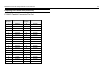
RS-232 Connector Pin Out
Null Modem Cable Pin Out
Pin Number Signal Name
1 HOST_DCD*
2HOST_SIN
3HOST_SOUT
4HOST_DTR*
5 GROUND
6HOST_DSR
7HOST_RTS*
8HOST_CTS*
9 No Connect.
9 Pin 9 Pin
1 DCD 7 RTS
8 CTS
2 RD 3 TD
3 TD 2 RD
4 DTR 6 DSR
5 GRD 5 GRD
6 DSR 4 DTR
7 RTS
8 CTS
1 DCD
99