August 2007 701P47496 Xerox 82xx/83xx Wide Format Printer Unwinder / Winder User Guide
Prepared by: Xerox Corporation Global Knowledge and Language Services 800 Phillips Road, Bldg. 0218-01A Webster, New York 14580-9791 USA ©2007 by Xerox Corporation. All rights reserved. Copyright protection claimed includes all forms and matters of copyrightable material and information now allowed by statutory judicial law or hereinafter granted, including without limitation, material generated from the software programs which are displayed on the screen such as icons, screen displays, looks, etc.
TABLE OF CONTENTS 1 Safety Instructions .................................................................................................................................... 1-1 1.1 Introduction........................................................................................................................................... 1-1 1.2 Important safety instructions ................................................................................................................ 1-1 1.3 Operation labels ...
This page is intentionally left blank.
1 SAFETY INSTRUCTIONS 1.1 INTRODUCTION Important BE SURE TO READ THE TERMS IN THE NEXT CHAPTER THOROUGHLY BEFORE INSTALLING AND OPERATING THE SYSTEM FOR YOUR OWN SAFETY. All safety related terms are bundled and categorized in three types.
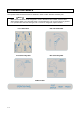
1.3 OPERATION LABELS The operation labels mentioned below are attached to areas to which attention should be paid. • • • Notes Make sure that all labels can be recognized. If text or illustrations are invisible, clean the label. When cleaning labels, use a cloth with water or neutral detergent. Do not use a solvent or gasoline. If an operation label has been damaged, lost or cannot be recognized, replace the label.
1.4 WEEE REGULATIONS WEEE regulations Environmental information Disposal of your old product Your product is designed and manufactured with high quality materials and components, which can be recycled and reused. When this crossed-out wheeled bin symbol is attached to a product it means the product is covered by the European Directive 2002/96/EC Please inform yourself about the local separate collection system for electrical and electronic products.
This page is intentionally left blank.
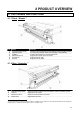
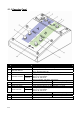
2 PRODUCT OVERVIEW 2.1 PART NAMES AND FUNCTIONS 2.1.1 Front / Winder (*) No 1 2 3 4 5 6 Name Front tensioning system Operation panel PCB Box Motorized roll unit Roll unit bar Roll unit Function Adjust the tension between the print platform and the winding system. To control the unwinder winder 100 manually or automatically Contains the boards to control the UW/W 100. Supports and winds up the roll media. Supports the roll units. Supports the roll media. 2.1.
2.1.3 Operation Panel No. A B Name / / 1 Print Side Selector 2 Unwinder 100 switch Manual 3 Unwinder 100 LED 4 5 6 Backwards button Forwards button Winder 100 switch 7 Winder 100 LED 8 9 10 Backwards button Forwards button Power LED Automatic Manual 2-2 Automatic Function Part of the operation panel controlling the unwinder 100. Part of the operation panel controlling the winder 100. In case you loaded media with printed side on the outside select ‘OUT’, otherwise select ‘IN’.
2.2 VERIFYING THE PACKAGED ITEMS Inspect the unit for damage and check that all necessary parts are present. Notes • The parts which are not described are buffers to hold the parts in their position and to protect them. 2.2.1 For Rockhopper 3, Spitfire and Viper. 2.2.1.
2.2.1.2 Winder kit No 1 Quantity 1 2 Hexagon key 2.
2.2.2 For ValueJet 1604 series. 2.2.2.
2.2.2.2 Winder kit . No 1 Quantity 1 2 Hexagon key 2.
3 INSTALLING THE UNIT 3.
3.2 INSTALL ALL PARTS 3.2.1 Mounting the roll unit bars Parts and Tools needed No 1 2 3 4 5 Description Roll unit bar Hexagon bolt M6x16 Plain washer M6 Tooth lock washer M6 Hexagon wrench 5 mm Quantity needed RH3 – SPFR ValueJet 2 2 8 8 8 8 8 8 1 1 Procedure Step 1 : 3-2 Position the roll unit bars (1) on the printer stand as shown on the image below.
Step 2 : Mount the left side of the bars with the mounting supports to the printer’s stand as indicated on the image below. No. 1 2 3 Step 3 : Description Plain washer M6 Tooth lock washer M6 Hexagon bolt M6x12 Check the gap (s) between the adjustable mounting support (1) on the right hand side and the printer stand and perform the correct action. This has to be done for both roll unit bars. See below.
3.2.2 Mounting the brackets for the tensioning bars 3.2.2.1 On a Spitfire, Rockhopper 3 and Viper Parts and Tools needed No 1 2 3 4 5 6 7 Description Right bracket Left bracket Hexagon bolt M6x16 Plain washer M6 Spring washer M6 Tooth lock washer M6 Hexagon wrench 5 mm Quantity 1 1 8 8 8 1 1 Instructions Step 1 : Mount the left and right bracket to the bottom of the X-rail. Note that the positioning of the left and right bracket is different depending on the size of the machine.
3.2.2.2 On a ValueJet 1604 Parts and Tools needed No 1 2 3 4 5 Description Right bracket Left bracket Self locking bolt M6x16 Tooth lock washer M6 Hexagon wrench 5 mm Quantity 1 1 8 1 1 Instructions Notes Before installing the winding system on a ValueJet, it is recommended to loosen screws fixing the printer from its stand and push it to the rear and tighten the bolts again. This to be sure that the machine is well positioned. Step 1 : Screw the self locking bolts half way in.
3.2.3 Installing the tensioning bars Parts and Tools needed No 1 2 3 4 5 6 7 Description Quantity RH3 & SPFR ValueJet 1604 1 1 1 1 2 2 4 4 1 1 1 1 Front tensioning bar Rear tensioning bar D-lock type shaft Pivot shaft Pan head screw flat M4x10 Philips screwdriver Hexagon wrench 5 mm Procedure Step 1 : Insert the two shafts (1) in the left (adjustable) bracket at the front and rear. front rear Caution Use care when lifting the tensioning bars to avoid bending the bars.
Step 3 : Fix the front and rear tensioning bar with 4 times an M4x10 screw. Caution Be sure to lock the front tensioning bar at both sides with 2 pan head screws. These screws have to be fixed before installing the front tensioning system! Caution Be sure to calibrate the complete system before using it. Please refer to the next chapter for this issue. Notes Install the remaining screws on the left bracket. Tighten all screws.
3.2.4 Mounting the PCB Box Parts and Tools needed No 1 2 3 4 Description PCB Box Screw M5x8 Washer M5 Hexagon wrench 3 mm Quantity 1 2 4 1 Procedure Step 1 : Mount the two screws with each two spacers to the stand. Step 2 : Place the PCB Box (2) against the stand and slide it with the holes over the screws (1) and push it downwards until it is fixed.
3.2.5 Connecting the cables. • • • Caution Use a power cable that is suitable to the local power specifications when connecting the UW/W 100 to the power grid. If the kit is separately ordered from a printer as an optional item, then a power cable is included in the UW/W 100 kit If the UW/W 100 kit has been delivered with a new printer as a standard in the box item, then the power cable is located in the printer’s packaging box, not in UW/W 100 packaging box.
3.3 CALIBRATING THE UW/W 100 3.3.1 Calibrating the rear tensioning system Parts and Tools needed Included in kit No. 1 2 3 4 Description Synthetic paper strip Hexagon wrench 2,5 mm Hexagon wrench 3 mm Hexagon wrench 4 mm No. 1 2 Description Tape Pencil Quantity 1 1 1 1 NOT included in kit Quantity 1 1 3.3.1.1 Checking the calibration The procedure below describes the calibration check of the rear tensioning system. The method to check the front tensioning system is the same.
Step 4 : Check if the edges of the loop are aligned on each other. Step 5 : Raise the pressure rollers. Slide the end of the strip (1) under the pressure rollers (4) and move it to position 1 as shown on the picture below. Lower the pressure rollers. No 1 2 3 4 Description Synthetic paper strip Paper loop Tensioning bars Pressure rollers Step 6 : Go to the FRONT SIDE of the printer. Step 7 : Carefully pull the strip to create some tension. • • Caution Don’t pull too hard on the strip.
PART 2 : DRAWING THE CONTROL LINES Step 1 : Place the adjustment plate onto the strip and slide it against the pressure rollers. Step 2 : Draw a line on the strip. Step 3 : Slide the strip (1) to position 2 as indicated on the image below.
Step 4 : • • Carefully pull the strip to create some tension. Caution Don’t pull too hard on the strip. This will loosen the tape, resulting in the fact that the loop becomes longer, leading to a bad calibration check. Make sure that you have an equal tension on the left and right of the strip. Step 5 : Place the adjustment plate onto the strip and slide it against the pressure rollers. See image below. Step 6 : Draw a line for the second time. The following two situations can be obtained.
3.3.1.2 Adjusting the tensioning systems Introduction The present topic describes the adjustment of the REAR tensioning system. The procedure to adjust the front tensioning system is the same. Procedure Step 1 : Standing at the REAR SIDE of the unit, remove the cover (1) of the adjustable bracket (3). Tool : Hexagon wrench 2,5 mm No 1 2 3 Step 2 : Loosen (don’t remove) the 4 screws on the side of the adjustable bracket.
Step 3 : Use the 2 screws (1) in the tension bar bracket to adjust the tension system. Referencing the figures below Line 1 is drawn in Position 1 and Line 2 in drawn in Position 2. Tool : Hexagon wrench 3 mm REAR REAR 1 = Adjustment screws IF Line 2 lays… THEN turn the adjustment screws as follows : BEFORE line 1 (Case A on image above) BEHIND line 1 (Case B on image above) • Caution Make sure to turn both adjustment screws an equal amount of turns.
3.3.2 Calibrating the front and rear roll unit bars. 3.3.2.1 Introduction The heights (hL and hR) on both sides of the roll unit bar (2) in relation to the printer stand (1) have to be adjust with spacers (3) to calibrate a roll unit bar (2),. FRONT VIEW No 1 2 3 Description Printer stand Roll unit bar Spacer 3.3.2.2 Checking the calibration of the roll units The procedure below describes the calibration check of the FRONT roll unit. The procedure to check the rear roll unit is the same.
Step 5 : Slide the end of the synthetic paper strip (1) under the pressure rollers (4) in position 1 of the printer until the synthetic paper strip (1) is a little tensioned. No 1 2 3 4 • • Description Synthetic paper strip Loop Core Pressure rollers Caution Don’t pull too hard on the strip. This will loosen the tape, resulting in the fact that the loop becomes longer, leading to a bad calibration check. Make sure that you have an equal tension on the left and right of the strip.
PART 2 : DRAWING THE CONTROL LINES Step 1 : Standing at the front side of the unit, place the adjustment plate onto the strip and position it against the pressure rollers as indicated on the image below. Step 2 : Draw a line. See image below. Step 3 : Slide the strip (1) to position 2 as indicated on the image below.
Step 4 : Place the adjustment plate onto the strip and slide it against the pressure rollers. Step 5 : Pull the strip so there is an equal tension. • • Caution Don’t pull too hard on the strip. This will loosen the tape, resulting in the fact that the loop becomes longer, leading to a bad calibration check. Make sure that you have an equal tension on the left and right of the strip. Step 6 : Draw a line for the second time. The following two situations can be obtained.
3.3.2.3 Adjusting the roll units Procedure Step 1 : Use the correct amount of spacers (2) to cover the space between the drawn lines (1). No 1 2 Step 2 : 3-20 Description Drawn lines Spacer Determine the deviation of the roll unit using the image and table below. IF line 2 lays… BEFORE line 1 BEHIND line 1 Adjusting the FRONT Units THEN… Remove spacers on the left front unit or add spacers on the right front unit. Add spacers on the left front unit or remove spacers on the right front unit.
Step 3 : Insert these spacers (1) at the left or right side (depending on the deviation determined in the previous step) BETWEEN the roll unit bar (3) and the printer’s stand (2). (See images below) No 1 2 3 Description Spacer Printer’s stand Roll unit bar Step 4 : Check the calibration of the roll system again and do an adjustment again if necessary. Step 5 : Now fix the screws of the roll unit bar so the bar doesn’t move anymore.
3.3.3 Adjusting the weight supports under the UW/W 100 Parts and Tools needed No. 1 Description Hexagon wrench 3 mm Quantity 1 3.3.3.1 Location of the weight supports on a 65” printer There are 2 weight supports on the UW/W 100 system for a 65” machine, see the images below for their positions. FRONT VIEW No 1 Description Weight support 3.3.3.
3.3.3.3 Adjusting the weight supports • Caution Don’t turn the weight supports with force when they reach the floor! Instructions Lower the weight supports of the UW/W 100 till they reach the floor. A hexagon wrench 6 mm can be used as indicated below.
This page is intentionally left blank.
4 OPERATING THE SYSTEM 4.1 TURNING THE POWER ON / OFF The switch in located on the power supply box. Its status is marked with “O” and “I”. “I” Switched ON Power LED on control panel of winding system will light up “O” Switched OFF Power LED on control panel of winding system will not be lid.
4.2 LOADING ROLL MEDIA Please follow the procedure below to install and load roll media. Step 1 : Make sure the printer and Unwinder/Winder 100 are switched ON. Step 2 : Raise the pressure rollers of the printer. Step 3 : Open the front cover Step 4 : Make sure both unwinder (REAR) and winder (FRONT) unit are set to MANUAL mode.
Step 9 : Be sure that the media is loaded centrally. This to be sure that the media is wound up straight. This can be easily checked by the yellow labels on the winding rails. Be sure to mount the left and right roll unit on the same distance from the 0I0 label. Step 10 : Install an empty core between the front roll units. a. Make sure the core is longer than the media width. b. Load it centrally as described in previous step Step 11 : Use the foot-switch to release some media at the rear.
Step 13 : Take the media on the front of the printer and pull until the rear tensioning system gently hits the back of the machine. This to become an equal tension. Step 14 : Lower the pressure rollers Step 15 : Set the unwinder (REAR) unit to AUTOMATIC. The rear tensioning system will go to its initial position. Notes Be sure to make the correct settings on the control panel of the winding system.