May 2008 701P48331 8265/8290/8365/8390 Wide Format Color Printer User Guide
COPYRIGHT NOTICE COPYRIGHT © 2008 Xerox. All rights reserved. This document may not be reproduced by any means, in whole or in part, without written permission of the copyright owner. This document is furnished to support the Xerox 8265/8290/8365/8390 Wide Format Color Printer Series.
This page has been intentionally left blank.
TABLE OF CONTENTS 1 Safety Instructions..................................................................................................... 1 1.1 Introduction ........................................................................................................... 1 1.2 Warnings, Cautions and Notes ............................................................................. 1 1.3 Important Safety Instructions ................................................................................ 1 1.
4.3.1 Setup Menu 1/7 ............................................................................................. 41 4.3.2 Setup Menu 2/7 ............................................................................................. 53 4.3.3 Setup Menu 3/7 ............................................................................................. 63 4.3.4 Setup Menu 4/7 ............................................................................................. 67 4.3.5 Setup Menu 5/7 ...................
6.6.2 Cleaning the Inside of the Printer................................................................. 128 6.6.3 Head Cleaning ............................................................................................. 128 6.7 LongStore Procedure........................................................................................ 131 6.7.1 Ready the Printer for LongStore .................................................................. 131 6.7.2 Starting up after a LongStore........................
This page has been intentionally left blank.
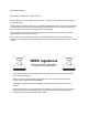
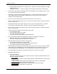
1 SAFETY INSTRUCTIONS 1.1 INTRODUCTION This chapter explains the meaning of safety terms for personnel who operate this equipment, important safety instructions, and the positions of the warning labels. Important Be sure to follow all instructions and warnings in this manual when using the equipment. 1.
1 Safety Instructions { { Earth terminals for telephone line or lightening rod → Doing so may cause a large flow of voltage if lightening occurs. Water pipes or faucets → If there is a plastic part in the pipe, the earth will not work properly. • Do not insert or drop metal or inflammable objects into openings, such as ventilation outlets. Doing so may result in electrical shock and fire. • Stop using your printer if a liquid has been spilled into it. This may cause electrical shock or fire.
1 Safety Instructions • Be careful not to pinch your fingers when opening and closing the cover of the ink compartment. • Be careful not to pinch your fingers when opening and closing the front cover. • Follow the instructions below when connecting the network interface cable. Otherwise, electrical shock or fire may occur. { Do not touch the connector. { Do not connect the network cable connector which has not the same specifications as the interface board.
1 Safety Instructions 1.4 WARNING LABELS The handling, attachment locations, and types of warning labels are explained below. Warning labels are attached on areas which require attention. Read and understand the positions and contents thoroughly before performing your work. 1.4.1 Handling the Warning Labels Be sure to note the following when handling the labels. Notes • Make sure that all labels can be recognized. If text or illustrations cannot be seen clearly, either clean or replace the label.
1 Safety Instructions No Type 1 2 3 4 5 8265/8290/8365/8390 User Guide 5
1 Safety Instructions 6 7 8 9 6 8265/8290/8365/8390 User Guide
1 Safety Instructions 10 1.4.2.2 No Location and Types of Warning Labels on the Rear of the Printer Type 3 CAUTION THIS UNIT HAS TWO POWER SUPPLY CORDS, WHEN WINDING UNIT IS PROVIDED. TO REDUCE THE RISK OF ELECTRICAL SHOCK, DISCONNECT ALL POWER SUPPLY CORDS BEFORE SERVICING.
1 Safety Instructions This page has been intentionally left blank.
2 PRINTER OVERVIEW 2.1 FEATURES The features of the printer are explained below. (1) High speed output Achieve high speed printing, maximum media width of 2280 mm and printing width up to 2250 mm. (2) Wide variety of compatible media Adjustable head height can be adapted to various media thickness from 0.08 up to 1.1 mm. (3) Vibrant Colour Reproduction To reproduce sharp and vivid colour, either 4 or 6 ink colours are used for printing.
2 Printer Overview 2.2 PART NAMES AND FUNCTIONS Part names and functions are explained below. 2.2.1 Front of Printer No Name Function Heater plate Supports and heats the media during printing. 2 Front cover Keeps the operator safe from the drive parts of the printer while it is operating. Only open and/or close the cover to perform following operations: • Media setting and replacement • Cutter blade replacement • Cleaning the cleaning wiper 3 Carriage Drives and holds the print heads.
2 Printer Overview 2.2.
2 Printer Overview 2.2.3 Position and Function of the Heating Elements Heater element Temperature Pre-heater (Heater A) 20 – 50°C Fixer (Heater B) 20 – 40°C • • Post-Fixer (Heater C) 20 – 70°C Dryer (Heater D) 20 – 50°C • • • • • Function Open the pores to make the media more receptive for 8365/8390 Mild Solvent Ink. To establish optimum fixation onto the media (coated and uncoated). Optimizes the dot gain control.
2 Printer Overview 2.2.4 Printer Control Panel The operation panel is used to set operational conditions, display the status of the printer, and set other functions. The names and functions of the operation keys and status lamps are explained below. 2.2.4.1 No 1 2 Operation keys Name [POWER] key [F1] key 3 [F2] key 4 [F3] key 5 [F4] key 6 [MENU ↑] key 7 [MENU ↓] key 8 [ENTER] key 9 [CANCEL] key Normal Turns the printer on and off. Executes the function assigned to F1.
2 Printer Overview 2.2.4.2 LCD Monitor and Light Indicators No 10 Name LCD monitor Colour - Status - 11 POWER lamp Green 12 ERROR lamp Red ON OFF Flashing 13 DATA lamp Orange 14 MEDIA SET lamp Orange OFF ON Flashing OFF ON OFF 15 ROLL lamp Orange 16 SHEET lamp Orange 17 HEATER lamp Orange ON OFF ON OFF ON Flashing OFF 14 Function The monitor displays the operation status and error messages of the printer. The printer is on. The printer is off. An error has occurred.
2 Printer Overview 2.2.5 Winder (Front) No 1 2 3 4 5 6 Name Front tensioning system Operation panel PCB Box Motorized roll unit Roll unit bar Roll unit Function Adjust the tension between the print platform and the winding system. To control the unwinder winder 100 manually or automatically Contains the boards to control the UW/W 100. Supports and winds up the roll media. Supports the roll units. Supports the roll media. 2.2.
2 Printer Overview 2.2.7 Winder/Un-winder Control Panel No. A B Name / / 1 Print Side Selector 2 Unwinder 100 switch 3 Unwinder 100 LED 4 5 6 Backwards button Forwards button Winder 100 switch 7 Winder 100 LED 8 9 10 Backwards button Forwards button Power LED Manual Automatic Manual 16 Automatic Function Part of the operation panel controlling the unwinder 100. Part of the operation panel controlling the winder 100.
2 Printer Overview 2.2.8 Winder/Un-winder Operation Labels The operation labels mentioned below are attached to areas to which attention should be paid. • • • Notes Make sure that all labels can be recognized. If text or illustrations are invisible, clean the label. When cleaning labels, use a cloth with water or neutral detergent. Do not use a solvent or gasoline. If an operation label has been damaged, lost or cannot be recognized, replace the label.
2 Printer Overview This page has been intentionally left blank.
3 PRINTER SETUP 3.1 TURNING THE PRINTER POWER ON/OFF The method to turn the power ON or OFF is described below. Caution Before powering ON the unit, make sure the waste bottle is installed. 3.1.1 Turning the Power ON Turn the power of the unit ON according to following procedure. Step 1 : Press the [POWER] key of the operation panel, to turn the unit ON. ¾ The POWER lamp of the operation panel will light (green). Step 2 : The unit will start initial start-up operations.
3 Printer Setup Notes When the printer is ON, the power LED is lid green. Push the power button again to turn off the machine. Step 3 : Following message is displayed for 3 seconds on the operation panel. Notes If pressing the [POWER] key on the operation panel by mistake, press the [POWER] key again while the following message is displayed. Step 4 : The product will perform the power OFF operation. ¾ Following message is displayed on the operation panel.
3 Printer Setup 3.2 TURNING THE WINDER/UN-WINDER POWER ON / OFF The switch in located on the power supply box. Its status is marked with “O” and “I”. “I” Switched ON Power LED on control panel of winding system will light up “O” Switched OFF Power LED on control panel of winding system will not be lid.
3 Printer Setup 3.3 CONNECTING THE NETWORK INTERFACE The procedure for connecting the network interface is explained below. To connect the printer to the network environment, follow the steps below. • Caution Follow the instructions below when connecting the network interface cable. Otherwise, electrical shock or fire may occur. o Do not touch the connector. o Do not connect the network cable connector to the interface board having different specifications. Step 1 : Turn off the printer.
3 Printer Setup 3.4 MEDIA HANDLING Media handling, attaching media, and setting media type are explained below. 3.4.1 Loading Sheet Media You can use the following sheet media with your printer. Maximum Media Width 2280 mm Printing Width Up To 2250 mm To load sheet media, follow the steps below. Notes If roll media is attached to the printer, wind the media up and then load the sheet media. Step 1 : Turn the printer on. Step 2 : The printer starts the initialize operation.
3 Printer Setup Notes When raising or lowering the pressurize rollers, you can use the foot switch instead of the operation panel. Step 5 : Open the front cover. Caution Be careful not to pinch your fingers when opening and closing the front cover. Step 6 : Load the sheet media into the insertion slot at the front of the printer. 1 2 Step 7 : • • Set the right edge of the media so that it is parallel with the media setting position.
3 Printer Setup ¾ Step 9 : The MEDIA SET lamp will turn off. Close the front cover. Step 10 : The media initial menu is displayed on the operation panel. 3.4.2 Loading Roll Media 3.4.2.1 Installing the media roll Step 1 : Determine the printable side of the media roll (inside or outside printing) and lay down the media roll as shown in the images below. Step 2 : Position the roll units of the unwinder in such a way that the media roll can be placed in between.
3 Printer Setup Step 5 : Slide the flange of the other roll unit into the roll and lock the unit by using its handle. Step 6 : You can now de-lock both sides to position the roll. Step 7 : Set the right edge of the media on the Unwinder so that it is parallel with the media setting position. 1 2 Roll media Media setting position Notes We recommend wearing cotton gloves to avoid fingerprints on the inkjet media. Step 8 : 3.4.2.2 Lock both sides of the Unwinder.
3 Printer Setup Printable side on the outside of the roll Printable side on the inside of the roll 1 = Unwinder 2 = Rear tensioning system 3 = Media insertion slot of the printer PART 2: LOADING THE MEDIA TROUGH THE FRONT TENSIONING SYSTEM Step 1 : Load the media through the printer’s pressure rollers. Step 2 : Standing in front of the printer, take the media and pull it until there is equal tension on the left and right of the media. Step 3 : Do not pull the media in the middle.
3 Printer Setup Notes With a small intervention it is possible to reverse your winding direction. Mount the twist cable between the control box and the front motorized unit cable. Notes You can use the roll-off foot switch during loading of roll media. 3.4.3 Setting Media Type The procedure for setting media type is explained below. Step 1 : Turn the printer on and load the media. ¾ Once the media has been set, the media initial menu will be displayed.
3 Printer Setup Step 3 : • Press the [Enter] key on the operation panel. ¾ The media type has been set. ¾ "Media Initial" is displayed on the LCD, and the printer starts the media initial operation. Notes The printer starts the media initial operation if you : o Press the [CANCEL] key on the operation panel o Leave the printer for 10 seconds without doing anything Step 4 : When the media initial operation finishes, the printer moves to normal status.
3 Printer Setup Step 5 : Select an item and press the appropriate key. Setup items Test Print (1/2) Test Print (2/2) Key name F1 Parameters Setup F2 Nozzle Check F3 Adj. Uni-D F4 Adj. Bi-D F1 Palette F2 Maintenance Descriptions Perform Setup List. Refer to ‘Setup List’ Perform Nozzle check. Refer to ‘Nozzle Check’ Perform the Uni-Directional Alighment. Refer to Adjustments Perform the Bi-Directional Alignment. Refer to Adjustments Perform Colour Palette.
3 Printer Setup 3.5.1 Setup List Use this function to check the current status of the printer.
3 Printer Setup 3.5.2 Nozzle Check Use this function to check if there is any clogging of nozzles, missing dots or faint printing. Notes If printing quality declines, or if missing dots are evident after the NozzleCheck, the print heads need to be cleaned. Refer to “Head cleaning" to perform head cleaning. After finishing the head cleaning, wait for 10 minutes and perform the NozzleCheck again.
3 Printer Setup 3.5.3 Colour Palette Use this function to compare the colour settings of the computer print colour of the printer. This palette is printed in the mode you are currently working (PrintMode settings). We recommend printing the palette in 360x360.
3 Printer Setup 3.5.4 Maintenance Record Use this function to check the life cycles of the printer parts. Notes A part's life cycle is shown by the amount of the * mark. When a part's life cycle comes to an end, the * mark reduces.
4 PRINTER OPERATION 4.1 PRINTER STATUS The status of the printer is explained below. 4.1.1 Normal Indicates that the printer can receive print data when media is loaded. You can also change printer settings using the operation panel.
4 Printer Operation 4.1.3 Changing the Printer Status To change the printer status, follow the steps below. 4.1.3.1 Changing the status from normal to the setting menu display Press either • or on the operation panel when the printer is in normal status. The display of the operation panel changes to the Setting menu display. Notes Refer to "Setup menu" for details of the setting menu. 4.1.3.
4 Printer Operation 4.2 USING MEDIA This section describes details on available media for the printer. 4.2.1 Media Type The type and quality of the media affect the results of drawing enormously. Refer to the description below and use the appropriate media for your purpose. The following are the recommended media for the printer. Select the appropriate media for your purpose. • • • • Notes For more information about the recommended media, contact your local Xerox Dealer.
4 Printer Operation 4.2.3 Precaution on Storing Media When storing media, pay attention to the following. • • • • Notes Do not store media in high temperature, high humidity, or direct sunlight. Store sheet media in the original bag after unpacking. Unused roll media must be removed from the scroller, rewound tightly, and stored in the original wrapping bag and the box. Do not wet media. 4.2.4 Media Printing Area The printing area is shown below.
4 Printer Operation 4.3 MENU OVERVIEW This section describes how to set the Menu settings on the operation panel, and setup items. Follow the steps below to set the Menu settings. Step 1 : Make sure that the operation panel is normal. Step 2 : Press the [MENU ▲] or [MENU ▼] key. I) The screen shows following Menu.
4 Printer Operation Notes The Network Settings menu is displayed if the network interface board has been installed on the product. The items on the File Management menu are displayed if a hard disk has been installed in the product. Setup items Parameters Description InkStatus Displays the information (ink status) for each ink cassette installed in the ink cassette slot. OriginSet Sets the printing start position (origin) for printing data. TestPrint Performs test printing.
4 Printer Operation 4.3.1 Setup Menu 1/7 4.3.1.1 InkStatus Menu Depending on the mode the printer is in (cassette or printer mode), this menu will be displayed as InkStatus. The InkStatus menu gives all information regarding the 8 ink cassettes in the slots. *InkStatus* K: Y: C: M: M: C: Y: K: UltraE *InkStatus* K: C: W: W: Y: M: C: M: MS 8265/8290 Setup items InkStatus Parameters Ink status for the ink cassette slots 1 – 8.
4 Printer Operation 4.3.1.2 OriginSet Menu Set the printing start position (origin) for printing data. Set this when you want to re-print to blank area of the printed media by changing the layout of the printing data. Setup items OriginSet Parameters • L: Media feed value • W: Print head movement value (Unit: mm) Description Changes the print head position and media feed amount by operating the following keys. • [F1] key: Feeds media forward. • [F2] key: Moves the print head to the left.
4 Printer Operation 4.3.1.3 TestPrint menu *TestPrint* Palette Maintenance Dist.Check (2/2) *TestPrint* Setup NozzleCheck Adj.Uni-D Adj.Bi-D (1/2) Setup items TestPrint (1/2) TestPrint (2/2) Parameters Setup NozzleCheck Adj. Uni-D Adj. Bi-D Palette Maintenance Dist.Check TestPrint (1/2-2/2) 4.3.1.4 Description Performs setup printing. Performs nozzle check printing. Performs accuracy adjustment printing in one direction. Performs accuracy adjustment printing in two directions.
4 Printer Operation 4.3.1.5 Media Menu Set media type for printing. Setup items Media (1/2) Media (2/2) Media (1/2-2/2) 44 Parameters User media 1 User media 2 User media 3 User media 4 User media 5 User media 6 User media 7 User media 8 - Description To set the type of media used for printing. For setup values of printing operation, eight settings of "user media 1-8" can be set. [CANCEL] key: to shift to the previous hierarchy menu.
4 Printer Operation 4.3.1.6 User Menu Make various settings on user defined media. In the User media menu, for each setup value of following printing operation, eight settings of "user media 1-8" can be set.
4 Printer Operation 4.3.1.7 InkDryTime Menu Set the waiting period between the end of operation and the start of next printing in order to let the printed media dry. Setup items InkDryTime 4.3.1.8 Parameters 0 to <30 sec. > to 270 sec. to 60 min. Description To change the InkDryTime by operating the following keys. • [F2] key: to increase the setup value. • [F4] key: to decrease the setup value. • [ENTER] key: to confirm the setup value • [CANCEL] key: to cancel the setup value H.
4 Printer Operation 4.3.1.9 Stiffness Menu Set the media sticking force (media stiffness) to the media guide. Setup items Stiffness Parameters Soft Normal - Description Setting for soft media where media feeding errors and media jams occur. Setting for normal media. After setting, shift to the previous hierarchy menu. 4.3.1.10 Thickness Menu Set the media thickness. Setup items Thickness Parameters 50µm-<100µm>1500µm Description Change media thickness by operating the following keys.
4 Printer Operation • • Notes The default setting for the heater is set to ‘50°C’. The function of the heater (A): Warming the transfer paper before entering the pressure rollers. The pre-expansion helps to minimize media cockling. 4.3.1.12 Fixer (B) Menu Set the temperature of the Fixer. Setup items Fixer (B) Parameters OFF – 40°C Description Change fixer temperature by operating the following keys. • [F2] key: to increase the setup value. • [F4] key: to decrease the setup value.
4 Printer Operation 4.3.1.14 Drier (D) Menu Set the temperature of the Drier. Setup items Drier • • Parameters OFF – 50°C Description Change drier temperature by operating the following keys. • [F2] key: to increase the setup value. • [F4] key: to decrease the setup value. • [ENTER] key: to confirm the setup value • [CANCEL] key: to cancel the setup value Notes The default setting for the drier is set to ‘50°C’.
4 Printer Operation 4.3.1.16 Dist. Adj Menu To perform various settings for media feed compensation Notes For details of the distance adjustment, refer to "Distance adjustment". Setup items Dist.Adj Parameters Print1 Change Print2 - Description Performs printing by media feed compensation. A correction pattern with a width of ± 0.20% (in steps of 0.10 %) is printed around the centre of the correction value currently set. Changes the media feed compensation value.
4 Printer Operation 4.3.1.18 Dist.Adj Menu Indicates that the Distance Adjustment test print is printing. Setup items Dist.Adj Parameters Data printing - Description Now printing by media feed compensation. Wait for a while until printing has been finished. • [CANCEL] key: to perform following operations : • Media feed correction printing has been finished. • To eject media. • To shift to the previous hierarchy menu. 4.3.1.
4 Printer Operation 4.3.1.20 TopFeed Menu Set the amount of media to be fed when printing begins. Make this setting when using roll media. Setup items TopFeed Parameters <0mm>-400mm Description To feed media at the start of printing. Set when printing on roll media. • [F2] key: to increase the setup value. • [F4] key: to decrease the setup value. • [ENTER] key: to confirm the setup value • [CANCEL] key: to cancel the setup value 4.3.1.21 MediaCut Menu Set media cut method after printing.
4 Printer Operation 4.3.2 Setup Menu 2/7 4.3.2.1 PrintMode Menu To perform various settings for Printing mode. Setup items PrintMode 4.3.2.2 Parameters Print mode 1 Print mode 2 Print mode 3 Print mode 4 - Description For each setup value of Printing mode, four settings of "Printing mode 1" - "Printing mode 4" can be set. [CANCEL] key: to shift to the previous hierarchy menu. PrnMode Menu Perform various settings for Print mode.
4 Printer Operation 4.3.2.3 Condition Menu Select the required printing quality.
4 Printer Operation 4.3.2.4 Direction Menu Set print head moving direction for printing. Setup items Direction 4.3.2.5 Parameters UniDir. BiDir. - Description Prints in one direction. Prints bi-directionally. [CANCEL] key: To shift to the previous hierarchy menu. RepeatPrn Menu Make settings for the repeat print. Setup items RepeatPrn 4.3.2.6 Parameters Count IntervalTime - Description To set the number of repeats per line of printing. To set interval time for the repeat print.
4 Printer Operation 4.3.2.7 IntervalTime Menu Set interval time for the repeat print. Setup items IntervalTime 4.3.2.8 Parameters <0.0 sec.> to 0.1 to 5.0 sec. Description To change interval time by operating the following keys. • [F2] key: to increase the setup value. • [F4] key: to decrease the setup value. • [ENTER] key: to confirm the setup value • [CANCEL] key: to cancel the setup value HeadSpeed Menu Only applicable when printing in 360dpi.
4 Printer Operation 4.3.2.9 Weaving Menu Without weaving ON, an image is completed (formed) by printing a series of complementary rectangular shaped stripes (bands, swaths, passes). Inherent to classic inkjet printing is that ink drying effects, stepping mismatch, miss firing nozzles show up in the printed image via ink bleeding and various types of banding.
4 Printer Operation Weaving method Sign / Quality User Tip Preferred setting for signage/poster applications containing big areas with solid colours or critical gradients and for photo quality output on coated media. (small loss of speed in 2 pass modes) Print Modes Supported 720x720 540x720 Picture / Speed Stitch Creates a fine print swath overlap. Mildly improves print quality versus “Off” setting.
4 Printer Operation 4.3.2.10 ScanWidth Menu It is possible to specify the carriage movement along the media – printed area. This will have a direct effect on the drying time!! Please find more details below. Setup items ScanWidth Parameters DataWidth MediaWidth FullWidth Description Carriage moves only over the printing area Carriage moves over the media Carriage moves over the full width Drying time Short Depending on MediaWidth Long 4.3.2.
4 Printer Operation 4.3.2.12 Step Menu Set the units for amount of movement for printing. Setup items Step Parameters <0.010mm> <0.025mm> - Description To set the printing units to 0.010mm. To set the printing units to 0.025mm. To shift to the previous hierarchy menu. Notes Please note that some software packages use the “step per mm” terminology, in which case a program step of 0.025 mm corresponds with 40 steps per mm and a program step of 0.010 mm with 100 steps per mm. 4.3.2.13 Resolu.
4 Printer Operation 4.3.2.14 OnlineTimer Menu Set time from the moment of receiving termination of printing data sent by computer to the recognition of end of printing data. Setup items OnlineTimer Parameters OFF/2sec. - <30sec.> 800sec. Description To change the Online time out time by operating the following keys. • [F2] key: to increase the setup value. • [F4] key: to decrease the setup value. • [ENTER] key: to confirm the setup value • [CANCEL] key: to cancel the setup value 4.3.2.
4 Printer Operation 4.3.2.17 CutPos. Menu Set the media cutting position after printing has been finished. Setup items CutPos. Parameters Standard - Description To cut the media to fit the media width, so that it meets the regulated size. To cut the media according to the size of the printing data. - Shifts to the previous hierarchy menu. 4.3.2.18 Function Menu Perform various settings for processing of printing data.
4 Printer Operation 4.3.3 Setup Menu 3/7 4.3.3.1 RollSetup Menu Perform various settings for roll media. Setup items RollSetup Parameters Disable Roll1 Roll2 Roll3 - 8265/8290/8365/8390 User Guide Description Set this when roll media setup is not used. For each setup value of roll media, 3 settings of "Roll media 1" - "Roll media 3" can be set. • [CANCEL] key: To shift to the previous hierarchy menu.
4 Printer Operation 4.3.3.2 Roll Menu Set media roll length. Setup items Roll 1-4 4.3.3.3 Parameters 1 m to <30 m>to 99 m Description To change roll media length by operating the following keys. • [F2] key: to increase the setup value. • [F4] key: to decrease the setup value. • [ENTER] key: to confirm the setup value • [CANCEL] key: to cancel the setup value Centro. Menu Set communication mode to Centronics interface. Setup items Centro. 64 Parameters Centro. .Bi Centro.
4 Printer Operation 4.3.3.4 Network Menu Make the settings for the network interface. Notes The Network Settings menu is displayed if the network interface board has been installed. Be sure to consult the network administrator before making the settings in the Network Settings menu. Setup items Network (1/1) Network 4.3.3.5 Parameters IPaddress SubnetMask Gateway - Description To set the IP address of the product. To set the subnet mask of the product. To set the IP address of the connected gateway.
4 Printer Operation 4.3.3.6 SubnetMask Menu Set the subnet mask of the product. Setup items SubnetMask 4.3.3.7 Parameters 000.000.000.000 <255.255.255.000> 255.255.255.255 Description Use the following keys to change the Subnet Mask. • [F1] key: Moves one digit to the left on the setting value to be changed. • [F2] key: Increases the setting value. • [F3] key: Moves to the right on the setting value. • [F4] key: Reduces the setting value.
4 Printer Operation 4.3.4 Setup Menu 4/7 4.3.4.1 Utility menu Perform various settings for application functions of products. *Utility* ErrorDisp. MediaDet. OnCleaning MediaWidth (1/3) *Utility* SlantCh. RemPanel (3/3) Setup items Utility (1/3) Parameters ErrorDisplay MediaDet. OnCleaning MediaWidth Utility (2/3) Prn+Wipe SmartTop AutoClean Utility (3/3) Utility (1/3 – 3/3) CapCycle SlantCh.
4 Printer Operation 4.3.4.2 ErrorDisp. Menu To set display method to the operation panel when minor error occurred. Setup items ErrorDisp. 4.3.4.3 Parameters Off On - Description No ErrorDisplay. To perform ErrorDisplay. To shift to the previous hierarchy menu. PaperDet. Menu To perform detection of width and edge of the media, when media has been initialized Setup items PaperDet. Parameters Normal OFF TakeUpRoll RollFeed - • • 68 Description To perform media detection automatically.
4 Printer Operation 4.3.4.4 OnCleaning Menu Set when cleaning should be performed automatically when the power is turned on. Setup items OnCleaning 4.3.4.5 Parameters Little Normal Powerful - Description Power on cleaning is not performed. Power on cleaning is performed. To shift to the previous hierarchy menu. MediaWidth Menu If media detection has not been performed during initialization, the width of the media is set here.
4 Printer Operation 4.3.4.6 Prn+Wipe Menu To take care of possible condensation on the head nozzle plate, it is possible to wipe while printing. Setup items Prn+Wipe 4.3.4.7 Parameters OFF High Middle Low - Description No wiping during printing After printing 10 passes, wiping cycle will be performed. After printing 16 passes, wiping cycle will be performed. After printing 22 passes, wiping cycle will be performed. • [CANCEL] key: To shift to the previous hierarchy menu.
4 Printer Operation 4.3.4.9 CapCycle Menu Perform a TubingFlush every 1 to 24 hours. Notes A TubingFlush is automatically performed after 10 minutes of idle and before shut down of the printer. Setup items CapCycle Parameters OFF 1 – 6 - 24 hours - Description No tubing flush will be performed Every 1 – 24 hours (adjustable) a TubingFlush is performed. • [CANCEL] key: To shift to the previous hierarchy menu. 4.3.4.10 SlantCh.
4 Printer Operation 4.3.4.12 Initial. Menu Return parameters to the factory settings. *Initial* Network Utility (3/3) Setup items Initial. (1/3) Initial. (2/3) Initial. (3/3) Initial. (1/3-3/3) Parameters All MediaSet PrintMode Command Layout Function RollSetup Centro Network Utility - Description Returns all parameters to the factory setting. Returns parameters in the media setup menu to the factory setting. Returns parameters in the print mode menu to the factory setting.
4 Printer Operation 4.3.4.14 MediaSet Menu Setup values of Media setup menu are set to the factory default settings. Setup items MediaSet Parameters OK - Description No initialization. To perform initialization. After setting, to shift to the previous hierarchy menu. 4.3.4.15 PrintMode Menu Setup values of Printing mode menu are set to the factory default settings. Setup items PrintMode Parameters OK - Description No initialization. To perform initialization.
4 Printer Operation 4.3.4.17 Layout Menu Setup values of Layout Setup menu are set to the factory default settings. Setup items Layout Parameters OK - Description No initialization. To perform initialization. After setting, to shift to the previous hierarchy menu. 4.3.4.18 Function Menu Setup values of Function setup menu are set to the factory default settings. Setup items Function Parameters OK - Description No initialization. To perform initialization.
4 Printer Operation 4.3.4.20 Centro. Menu Setup values of Centronics menu are set to the factory default settings. Setup items Centro. Parameters OK - Description No initialization. To perform initialization. After setting, to shift to the previous hierarchy menu. 4.3.4.21 Network Menu Setup values of Network menu are set to the factory default settings. Setup items Network Parameters OK - Description No initialization. To perform initialization.
4 Printer Operation 4.3.5 Setup Menu 5/7 4.3.5.1 DataDump Menu To perform dump printing for online function check. DataDump Parameters Start/End All - 4.3.5.2 Notes Dump printing is used by service persons to check the functions of the printer. Do not use this function for normal printing. • [CANCEL] key: • To exit Dump Mode. • To shift to the previous hierarchy menu.
4 Printer Operation 4.3.5.3 HeadWash Menu To perform a head wash to remove all ink of the ink supplying system. Setup items HeadWash Parameters No Yes - Description Do not wash the ink supplying system. To wash the ink supplying system. • [CANCEL] key: shift to the previous hierarchy menu. Notes Only after two head wash cycles it is possible to change ink types. Use the ‘Ink Load‘ to load ink The process consists of several cleaning loadings, several air loadings and one ink loading.
4 Printer Operation 4.3.5.5 InkChange Menu Change the ink configuration (from 2x4 to 1x6 or opposite). Setup items InkChange Parameters No Yes - Description Do not perform an ink change. To start the ink change cycle. • [CANCEL] key: shift to the previous hierarchy menu. Notes To reduce the consumption of ink and cleaning liquid it is recommended to change ink types by using the ‘Ink Change’ cycle. The process consists of several cleaning loadings, several air loadings and one ink loading.
4 Printer Operation 4.3.5.6 Longstore Menu (8365/8390 Only) When storing the printer for longer than 5 days, ink cassettes with 8365/8390 Cleaning liquid should be installed. For more details, please refer to maintenance cycle. Setup items Longstore Parameters No Yes - Description Do not perform a long store Perform the long store procedure. • [CANCEL] key: shift to the previous hierarchy menu. The process consists of several cleaning loadings, several air loadings and one ink loading.
4 Printer Operation Message 1. Power ON without Ink Cassettes installed. 2. Insert Cartridges 3. Auto InkFill Time 13 Notes When powering ON and INK cassettes are already installed, the message “Not Original Ink” will be displayed. Remove 1 and reinsert it, then the procedure will continue. 4.3.5.7 InkSupply menu This setting should be enabled (ON) when using the Bulk Ink System. Important Please refer to the user’s Guide of the Bulk Ink System to know how to install and use it.
4 Printer Operation 4.3.6 Setup Menu 6/7 4.3.6.1 H.Unlock Menu *H.Unlock* No *H.Unlock* Yes (1/1) Setup items H.Unlock 4.3.6.2 Parameters No Yes - To lock heads press -> ENTER Description Cancels unlocking the carriage. Unlocks the carriage. • [CANCEL] key: shifts to the previous hierarchy menu. WiperClean Menu Clean the wipers. Notes Refer to "Cleaning the cleaning wiper" for details regarding the procedure for cleaning the cleaning wiper.
4 Printer Operation 4.3.6.3 TankCng. Menu Change the waste fluid tank. Set when changing the waste fluid tank. Notes Refer to "Replacing the waste liquid tank" for details regarding the procedure for changing the waste fluid tank. Setup items TankCng. 4.3.6.4 Parameters Cancel Enter - Description Do not change the tank. When tank has been changed. • [CANCEL] key: shifts to the previous hierarchy menu. TubingFlush Menu Removes rest fluids out of the capping station and waste tubes to prevent clogging.
4 Printer Operation 4.3.7 Setup Menu 7/7 *SetupMenu* VersionCheck Area (7/7) 4.3.7.1 VersionCheck Menu Check the installed firmware and heater system version. Setup items Version Check 4.3.7.2 Parameters - Description • [CANCEL] key: shift to the previous hierarchy menu. Area Menu View the total area of media printed on the machine. *Area* Total 46.16m2 Setup items Area Parameters Total - 8265/8290/8365/8390 User Guide Description Total area of media.
4 Printer Operation 4.4 OPERATING FROM THE CONTROL PANEL This section describes functions operated on the operational panel when the printer is in the normal status. Notes For information of the name and function of each key, refer to "Operation panel". 4.4.1 Feeding Media When you want to feed media forward or backward, follow the steps below: Step 1 : Verify the following regarding the condition of the printer. I) It is not currently printing Step 2 : Press the [F1] key of the operation panel.
4 Printer Operation Step 4 : Press the [F3] key or the [F4] key on the operation panel. I) The product will perform following operations: Setup items Cut & Feed Key name F3 F4 Parameters Forward Backward Description Feeds media forward. Feeds media backward. Notes If "Take-Up Roll" is set in the media detection setup menu, the product will not operate even if the [F4] key has been pressed. 4.4.
4 Printer Operation 4.4.2.2 Change the fixer temperature To change the temperature of the fixer, press the [F2] key on the operation panel. The display will mention the following: Press the [F2] key to decrease the temperature. Press the [F4] key to increase the temperature. Press the [ENTER] key to confirm the requested temperature change. Press the [CANCEL] key to leave the menu without changing the heater settings. 4.4.2.
4 Printer Operation Please note that after finishing a printing job (and no other print job is sent to the printer the heating elements will keep their temperature for approximately 6 minutes. After 6 minutes the heating elements are powered OFF. 4.4.3 Operating the Pressure Rollers When you want to switch the up and down movement of the pressure rollers follow the steps below. Step 1 : Press the [F4] key on the operation panel. I) The printer works as follows.
4 Printer Operation 4.5 CONTROL PANEL DURING PRINTING When sending a file to your printer, following messages can be displayed. 4.5.1 Heaters are not Ready during Printing When the heaters are not reached their target temperature, the following screen will be displayed. Wait Heating Dist.Adj. Cleaning A: HB: HC: HD:H Heater Warming up Still, it is possible to start the print. However, the heater will continue to warm up in order to reach the requested temperature.
4 Printer Operation Notes For more details about step adjustment, please refer to “Media Feed Compensation” 2) Cleaning While printing, it could be possible that some nozzles drop out, in that case, perform a little, normal or powerful cleaning. Please follow the steps below to perform a cleaning. When there are some missing nozzles, a cleaning should be done. Depending on the quantity of missing nozzles and which head, a little, normal or powerful cleaning on head 1-2, head 3-4 or ALL could be done.
4 Printer Operation Step 3 : Change the value of one or more heaters or turn them all off. Notes For more details about heater adjustment, please refer to “Controlling the heater elements on the 8265/8290/8365/8390 printer” 4.6 OPERATIONS AFTER PRINTING 4.6.1 Cutting Media The media cutting procedure is described below. Roll media is automatically cut after printing when "Auto" is set on the cut media menu and roll media has been set.
5 TROUBLESHOOTING 5.1 INTRODUCTION This chapter explains troubles that may occur when using the printer and how to solve them. If you encounter an error not described in this chapter, refer to "Error messages" and contact your local Xerox Customer Service Representative. 5.2 FAILURES AND MALFUNCTIONS OF THE PRINTER This section describes the failures and malfunctions of the printer not displayed as errors, causes and solutions. (1) The printer does not work after the power has been turned on. No.
5 Troubleshooting (3) The printer does not work after data has been sent from a computer. No. 1 Possible cause Ink cassette is empty. Solutions Replace the ink cassette. Reference Refer to ‘Replacing ink cassettes’ (4) The printer does not print and an error is generated after data has been sent from a computer. No. 1 2 Possible cause The model setting of the computer is not correct. The interface setting or command mode on computer and printer do not match.
5 Troubleshooting (7) Media jams occur frequently. Notes We cannot ensure correct media feeding with media other than recommended media. No. 1 2 3 4 5 Possible cause You did not use recommended media. You used the printer in an environment other than the specified environment. You used old media. You used folded, creased, or curled media. Check the media for curling or liftoff. Solutions Use recommended media. Use the printer in the specified environment.
5 Troubleshooting (10) The media is off or damaged when loading it. Notes Remove the jammed or damaged media, referring to "When media jams occur". No. 1 2 3 4 5 6 7 94 Possible cause You did not use recommended media. The loading position of the media is not correct. Foreign material, such a piece of media, is attached to the pressure rollers. You used the printer in direct sunlight or other locations not appropriate for the specified environment. You loaded sheet media into the printer.
5 Troubleshooting (11) Media is damaged during media Initial. Notes Remove the jammed or damaged media. No. 1 2 3 4 5 6 7 Possible cause You did not use recommended media. The loading position of the media is not correct. You did not load the media straight into the printer. Foreign material, such a piece of media, is attached to the pressure rollers. You used the printer in a location with air conditioner or other location not appropriate for the specified environment.
5 Troubleshooting (14) Media is crooked while printing. No. 1 2 Possible cause You did not use recommended media. The loading position of the media is not correct. Solutions Use recommended media. Load the media correctly. References Refer to ‘Media type’ Refer to ‘Loading media’ (15) The printer is not connected to a computer using the Centronics interface. No. 1 2 Possible cause When the printing data is transferred from the computer, the DATA lamp on the operation panel is not lit.
5 Troubleshooting (17) White or black lines on printouts. No. 1 Possible cause You did not use recommended media. Solutions Use recommended media. References Refer to ‘Media type’ Solutions Use a new ink cassette. References Refer to ‘Replacing ink cassettes’ Use recommended media. Try minor adjustments for image quality. Refer to ‘Media type’ Solutions Use recommended media.
5 Troubleshooting 5.3 ERROR MESSAGES This chapter explains the messages displayed on the operation panel both when the printer works normally and when an error occurs, and possible solutions. 5.3.1 Status Messages The following are the status messages while the printer works normally. (1) Displays the operational status (1) The following operational status is displayed on the first line of the operation panel. No.
5 Troubleshooting No. 1 Display Ink Refill **min 2 During cleaning **min 3 Media Initial ******** 4 During discharge Wait for a while During washing Wait for a while 5 Solutions The printer performs ink charging. Wait for a while. The printer performs head cleaning. Wait for a while. The printer performs initial setting of media. Wait for a while. Indicates the media type setting made. The printer performs head cleaning and ink discharging. Wait for a while. The printer performs a head cleaning.
5 Troubleshooting (2) Error messages regarding warnings of the remaining ink The following error message is displayed on the forth line on the operation panel. No. 1 Display Near End [*] Descriptions The ink is running short in the ink cassette. (The printer continues to perform.) Solutions Prepare a new ink cassette.
5 Troubleshooting 5.3.3 Data Error Display and Solutions Following are data errors and possible solutions during printer operations. Data errors are displayed when a communication error occurs between computer and printer. If data error occurs, the following error messages are displayed and the printer stops. Solve the problem to delete the error message and restart the printer. No. 1 Message Online status I** Error [ ] Descriptions An error has occurred while receiving data.
5 Troubleshooting 5.3.5 Error Requiring a Printer Restart Following are descriptions and solutions requiring a restart. Errors requiring a restart are displayed when the following fatal error has occurred during printer operation. • • • Foreign material disturbing the printer operation is involved in the printer. An electrical circuit (such as board, motor, or sensor) failure has occurred. An error on the control program has occurred.
5 Troubleshooting 5.4 WHEN MEDIA JAMS OCCUR If the loaded media gets jammed in the printer, follow the steps below to remove the media. Step 1 : Press [F4] to raise the pressure rollers. Notes For raising or lowering the pressure rollers, you can use the foot switch instead of the operation panel. Step 2 : If a piece of media or media dust is stocked in the printer, open the front cover and remove the piece of media or media dust.
5 Troubleshooting This page has been intentionally left blank.
6 MAINTENANCE 6.1 INTRODUCTION This chapter explains the necessary daily, weekly and monthly maintenance of the printer. Be sure to perform the recommended maintenance strictly. If not, Xerox does not guarantee constant printing quality. 6.2 8265/8290 PERIODIC MAINTENANCE This section describes the periodic maintenance required for this machine. This maintenance helps ensure stable image quality. In the periodic maintenance, some service parts may be checked, cleaned, or replaced.
6 Maintenance No 1 2 Description Quantity Spitfire Mild Solvent Cleaning Liquid Ink kit Black Cyan Magenta Yellow 8 2 2 2 2 4. Solvent cleaning in a bottle 6.2.1 Weekly Maintenance At the end of the week, ink has to be removed from some parts, so it cannot harden. Otherwise, some parts will break down or result in bad print quality. After performing a weekly maintenance, do not forget to perform the daily maintenance afterwards. 6.2.1.
6 Maintenance 6.2.1.2 Cleaning around the bottom of heads Step 1 : Open the left maintenance covers by removing the four screws. Step 2 : Power ON the printer. Step 3 : Go to the H.Unlock Menu and press the F2 key to unlock the carriage. Step 4 : Open the Front Cover. Step 5 : Slide the carriage into the left maintenance area. Step 6 : Clean the edges of the heads with a cleaning swab wetted by Eco-solvent Cleaning Liquid.
6 Maintenance Step 5 : Close the Front Cover. Step 6 : Press the [ENTER] key to exit the H.Unlock Menu. The carriage will cap in and be locked 6.2.2 Bi-weekly Maintenance 6.2.2.1 Cleaning the wipers Step 1 : Power ON the printer. Step 2 : Go to the WiperClean Menu and press F2. Step 3 : Open the Front Cover. Step 4 : Clean the wipers (4) with a poly-knit wiper. Use some Eco-solvent cleaning liquid to remove drops of ink. • Caution It is recommended to wear gloves.
6 Maintenance 6.2.3 Monthly Maintenance 6.2.3.1 Replacing the wipers Step 1 : Power ON the printer. Step 2 : Go to the WiperClean Menu and press F2. Step 3 : Open the Front Cover. Step 4 : Remove the old wipers with a pair of tweezers Step 5 : Before inserting a new wiper, moisten the wiper with Eco-Solvent Cleaning Liquid. Step 6 : Insert the moistened wiper with a pair of tweezers.
6 Maintenance 6.2.3.2 • Replacing the sponge in the spitting box. Notes Use gloves and tweezers to change the absorbent in the flushing box. Step 1 : Power ON the printer. Step 2 : Go to the H.Unlock Menu and press the F2 key to unlock the carriage. Step 3 : Open the Front Cover. Step 4 : Slide the carriage to the left to access the flushing sponge. Step 5 : Remove the old flushing sponge with tweezers.
6 Maintenance 6.2.4 Semi-Annual Maintenance 6.2.4.1 Change upper sponge at back of the capping station. Step 1 : Power ON the printer. Step 2 : Go to the H.Unlock Menu and press F2. Step 3 : Open the Front Cover. Step 4 : Slide the carriage to the left to access the upper sponge. Step 5 : Remove the two screws fixing the sponge (1). 1 = Screws fixing the sponge (1) Step 6 : Replace the sponge and tighten it again to the plate with the two screws.
6 Maintenance 6.3 8365/8390 PERIODIC MAINTENANCE This section describes the periodic maintenance required for this machine. This maintenance helps ensure stable image quality. In the periodic maintenance, some service parts may be checked, cleaned, or replaced. Perform periodical inspections according to the table below.
6 Maintenance 6.3.1 Daily Maintenance Before every print, perform a nozzle check. If some nozzles are missing or misfiring, perform cleaning cycles until all nozzles are in good shape. We advise to run a normal or a powerful cleaning cycle to recover the nozzles. At the end of the day, when you will shut down the printer, the ink has to be removed from some parts, so it cannot harden. Otherwise, some parts will break down or result in bad print quality.
6 Maintenance 6.3.1.2 Tubing Flush and Maintenance Station Cap Flush Step 1 : Power ON the printer. Step 2 : Go to SetupMenu 6/7 and press F4 to select TubingFlush. Step 3 : Open the front cover Step 4 : Use a pipette to flush the caps with Mild Solvent Cleaning Liquid. Flush the caps until the color of the mousse in the cap does not change anymore. 1 2 Pipette Caps Step 5 : Close the Front Cover. Step 6 : To stop the tubing flush cycle press enter. 6.3.1.
6 Maintenance 6.3.2 Weekly Maintenance At the end of the week, ink has to be removed from some parts, so it cannot harden. Otherwise, some parts will break down or result in bad print quality. After performing a weekly maintenance, do not forget to perform the daily maintenance afterwards. 6.3.2.1 Cleaning the area around the caps Step 1 : Power ON the printer. Step 2 : Go to the H.Unlock Menu and press F2. Step 3 : Open the Front Cover.
6 Maintenance Step 4 : Open the Front Cover. Step 5 : Slide the carriage into the left maintenance area. Step 6 : Clean the edges of the heads with a cleaning swab wet with Mild Solvent Cleaning Liquid. Make sure you do not touch, clean the nozzle plate; this would lead to poorer print quality. • • Caution Make sure not to touch the nozzle plate. This could lead to poorer print quality. It is recommended to wear gloves (2) as shown on the picture below.
6 Maintenance 6.3.3 Bi-weekly Maintenance 6.3.3.1 • Replacing the sponge in the spitting box. Notes Use gloves and tweezers to change the flushing sponge in the flushing box. Step 1 : Power ON the printer. Step 2 : Go to the H.Unlock Menu and press the F2 key to unlock the carriage. Step 3 : Open the Front Cover. Step 4 : Slide the carriage to the left to access the flushing sponge. Step 5 : Remove the old flushing sponge with tweezers.
6 Maintenance 6.3.4 Monthly Maintenance 6.3.4.1 Replacing the wipers Step 1 : Power ON the printer. Step 2 : Go to the WiperClean Menu and press F2. Step 3 : Open the Front Cover. Step 4 : Remove the old wipers with a pair of tweezers Step 5 : Before inserting a new wiper, moisten the wiper with Eco-Solvent Cleaning Liquid. Step 6 : Insert the moistened wiper with a pair of tweezers.
6 Maintenance 6.3.4.2 Change upper sponge at back of the capping station. Step 1 : Power ON the printer. Step 2 : Go to the H.Unlock Menu and press F2. Step 3 : Open the Front Cover. Step 4 : Slide the carriage to the left to access the upper sponge. Step 5 : Remove the two screws fixing the sponge (1). 1 = Screws fixing the sponge (1) Step 6 : Replace the sponge and tighten it again to the plate with the two screws. 1 = Capping sponge 2 = Plate Step 7 : Close the Front Cover.
6 Maintenance 6.
6 Maintenance 6.5 REPLACING CONSUMABLES This section explains when to replace ink cassettes, roll media, or the cutting blade and the procedures for replacement. 6.5.1 Replacing Ink Cassettes Read the following for information on when and how to replace ink cassettes. (1) Replacement time Replace ink cassettes under the following conditions. a. The ink remaining in the ink cassette is low. o The following message is displayed on the operation panel. o Printing operation is continued.
6 Maintenance (3) Replacement procedure • • • Caution When handling ink cassettes, be careful that ink does not get in your eyes or on your skin. However, if this happens, flush immediately with water. Otherwise, your eyes may become congested or slightly inflamed. If you feel discomfort, consult a doctor immediately. Do not disassemble ink cassettes. Otherwise, ink may get in your eyes or on your skin. Only use 8265/8290/8365/8390 Ink and appropriate cleaning liquid.
6 Maintenance Step 4 : Take the new ink cassette from its package. Notes Unpack the ink cassette just before installing it into the ink cassette slot. If you leave the cassette unpacked for a long time, the printer may not be able to print correctly. Use up ink cassettes within two years from the date printed on the cassette packages. Replace ink cassettes if after six months since installation. Step 5 : Gently shake the ink cassette the install the ink cassette in the slot.
6 Maintenance 6.5.2 Replacing the Cutting Blade Read following information on when and how to replace the cutting blade. (1) Replacement time Replace the cutting blade under the following conditions. a. Media cannot be cut cleanly b. The message "media Cut Error" appears on the operation panel if a media cutting error occurs. c. When the cut edge has scuffing (2) Replacement procedure Follow the steps below to replace the cutting blade.
6 Maintenance 1 2 Step 6 : Cutting blade holder lever Cutting blade holder Take out the cutting blade (1). Notes Do not touch the edge of the cutting blade to avoid injury. Do not drop the cutting blade or apply it on hard material. Doing so may damage or break the cutting blade. Dispose the used cutting blade; put it in a plastic bag in accordance with local regulations or laws. Step 7 : Insert the new cutter into the media cutting blade holder.
6 Maintenance 6.5.3 Replacing the Waste Tank Read following information on when and how to replace the waste liquid tank. (1) Replacement Time Replace the waste liquid tank under the following conditions. a. When the waste liquid tank is nearly full. • • • Following message is displayed on the operation panel. Printing continues. Prepare a new waste liquid tank before the waste liquid tank becomes full. (2) Replacement Procedures Follow the steps below to replace the waste liquid tank.
6 Maintenance 6.6 CLEANING You need to clean the printer periodically to keep it in best working condition. • • • • • Important Do not insert or drop metal or inflammable objects into openings, such as ventilation outlets. Doing so may result in electrical shock and fire. Stop using your printer if a liquid is spilled into it. This may cause electrical shock or fire. Power the printer OFF as soon as possible, unplug the power cord and then contact your local XEROX dealer.
6 Maintenance 6.6.2 Cleaning the Inside of the Printer (1) Cleaning frequency Clean once a month. (2) Cleaning procedure The following are instructions for cleaning the inside of the printer. Follow the steps below. Step 1 : Open the front cover. 1 Step 2 : Front Cover Use a soft brush to carefully clean away any dust or dirt on the pressure rollers. Notes Do not blow off media dust inside the printer using an air dusting machine. Doing so may cause noise to occur from inside the printer.
6 Maintenance Caution Be sure not to pinch your fingers while opening and closing the front cover. Step 2 : Refer to "TestPrinting" to perform nozzle check printing. Step 3 : Check if the print head, referring to the diagram below. Step 4 : Check the printer is in the normal status. Step 5 : Press the [F2] key on the operation panel. I) The printer enters the cleaning menu. Step 6 : Press the [F2] key on the operation panel to change the parameters.
6 Maintenance Step 8 : When the head cleaning has been completed, the printer returns to the normal status. Notes We advise to let the printer rest for 5-10 minutes after a head cleaning procedure. During that time, the 8265/8290/8365/8390 ink comes to a fully stabilized condition, improving print quality considerably. Step 9 : Perform a nozzle check again and check the print head.
6 Maintenance 6.7 LONGSTORE PROCEDURE The purpose of this procedure is to place the 8365/8390 in a storage condition by removing the ink in the ink lines and replacing it with cleaning liquid. It should be use to prepare the printer for transportation or whenever the printer will be left unattended for five days or more 6.7.1 Ready the Printer for LongStore Step 1 : At the Printer Control Panel, go to the LongStore menu (SetupMenu 5/7 ► InkManager 2/2 ► LongStore ► F2) Step 2 : Press F2 Yes.
6 Maintenance This page has been intentionally left blank.
7 ADJUSTMENTS 7.1 UNI-DIRECTIONAL ADJUSTMENT The Uni-directional (Uni-D) Adjustment is used to align print head 2, 3 and 4 (Adjustment Head) to print head 1 (Reference Head) for uni-directional printing (right-to-left only). It should be performed whenever the printing environment or the media type is changed. Step 1 : Power ON the printer and setup the media at the control panel. Step 2 : Print the Uni-D Test Print. At the control panel, navigate to Setup Menu 1/7 and select F3 TestPrint > F3 Adj.
7 Adjustments At the Control Panel, press either the F2 key or F4 key to select the number determined in the previous step. Using the previous steps example, you would press either F2 or F4 to until the display read “4”. Step 4 : Press the [Enter] key on the control panel to set the Uni-D Alignment value for “Head 2". Step 5 : Repeat steps 3 through 5 to set the Uni-D Alignment for Print Heads 3 and 4. Step 6 : Repeat step 2 and analyze the Uni-D Test Print. again.
7 Adjustments 7.2 BI-DIRECTIONAL ADJUSTMENT The Bi-directional (Bi-D) Adjustment is used to set the timing of a print head when using bi-directional printing. It ensures that the left-to-right pass of the carriage (Adjustment Pass) is aligned with the right-toleft pass (Reference Pass). It should be performed whenever the printing environment or the media type is changed. Step 1 : Power ON the printer and setup the media at the control panel. Step 2 : Print the Bi-D Test Print.
7 Adjustments Step 4 : At the Control Panel, press either the F2 key or F4 key to select the number determined in the previous step. Using the previous steps example, you would press either F2 or F4 to until the display read “4”. Step 5 : Press the [Enter] key on the control panel to set the Bi-D Alignment value for “Head 1A". Step 6 : Repeat steps 3 through 5 to set the Bi-D Alignment for the remaining Print Heads (1B, 2A, 2B, 3A, 3B, 4A, and 4B).
7 Adjustments 7.3 STEP ADJUSTMENT A key factor in ensuring the consistent print quality on your Xerox 8265/8290 or 8365/8390 Wide Format Printer is setting the correct “Step” or “Feed” distance for the media type being used. The following procedure will allow you to check and, if necessary, adjust the “step” distance of your Xerox Inkjet Printer. It should be performed anytime you change the media type. 7.3.1 Print the Dist.Check Test Pattern Step 1 : Power ON the printer.
7 Adjustments 7.3.2 Evaluate the Dist. Check Test Pattern Step 1 : To evaluate the print, you should look for gaps or overlaps between the different passes. Examples For print 1, the step is too small, overlap is visible. Step overlap/Step too small Print 1 For print 2, the step is too big, there is a gap visible.
7 Adjustments 7.3.3 Modify the Step Adjust Printer Setting Step 1 : At the Control Panel press the Cancel button until Control Panel Screen displays “Ready to Print”. Step 2 : Press F1 Cut&Feed. Step 3 : Press F2 Dist. Adj.. Step 4 : Change the Step Adjust Printer Setting: a. If the Dist. Check Test Pattern has OVERLAP, as shown in Print 1, then you need to increase the Step Adjust Printer Setting. To do this: i. Press the F2 Key to increase the Step Adjust Printer Setting %. ii. Then press ENTER.
7 Adjustments This page has been intentionally left blank.
8 APPENDIX 8.1 PRODUCT SPECIFICATIONS Technology Media Thickness Compensation Maximum Media Widths Maximum Print Widths Media Thickness Diameter Core Weight Colour Channels Inks Ink Cassette Capacity Print Modes & Panel Control Options LCD Display Take-up System (standard) Roll Media Core Interface Power Consumption External Dimensions in mm (W x D x H) Weight Power Supply Working Environment Noise Level Standard Optional Item RIP Specifications Drop-on-demand Micro Piezo Inkjet Technology.
8 Appendix This page has been intentionally left blank.
Prepared by: Xerox Corporation Global Knowledge and Language Services 800 Phillips Road, Bldg. 0218-01A Webster, New York 14580-9791 USA ©2008 by Xerox Corporation. All rights reserved. Copyright protection claimed includes all forms and matters of copyrightable material and information now allowed by statutory judicial law or hereinafter granted, including without limitation, material generated from the software programs which are displayed on the screen such as icons, screen displays, looks, etc.