October 2008 701P48934 6030 / 6050 / 6050A / 510 Series / 721P / 6204 / 6279 Wide Format Copy System User Guide
Xerox Corporation Global Knowledge and Language Services 800 Phillips Road 218-01A Webster, New York 14580 ©2008 by Xerox Corporation. All rights reserved. Copyright protection claimed includes all forms and matters of copyrightable material and information now allowed by statutory judicial law or hereinafter granted, including without limitation, material generated from the software programs which are displayed on the screen such as icons, screen displays, looks, etc.
Table of Contents 1 SAFETY NOTES......................................................................................................................................................1 WARNING – ELECTRICAL SAFETY INFORMATION ....................................................................................................2 OPERATIONAL SAFETY INFORMATION ........................................................................................................................3 MAINTENANCE INFORMATION .........
Table of Contents What is a bad quality document?.........................................................................................................................43 PREPARING DOCUMENTS ..........................................................................................................................................44 SCANNING STRATEGIES ............................................................................................................................................
Table of Contents Transform ............................................................................................................................................................86 SAMPLE KEY .............................................................................................................................................................88 Copy Mode Sample ........................................................................................................................................
Table of Contents Problem Solving Table ......................................................................................................................................149 Error Code Messages Table ..............................................................................................................................153 14 SPECIFICATIONS ............................................................................................................................................
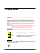
1 Safety Notes Read these safety notes carefully before using this product to ensure that you operate the equipment safely. Your Xerox/Fuji Xerox product and recommended supplies have been designed and tested to meet strict safety requirements. These include safety agency approval, and compliance with established environmental standards. Please read the following instructions carefully before operating the product and refer to them as needed to ensure the continued safe operation of your product.
1 Safety Notes WARNING: This product must be connected to a protective grounded circuit. This product is supplied with a plug that has a protective grounding pin. This plug will only fit into a grounded electrical outlet. This is a safety feature. To avoid risk of electric shock, contact your electrician to replace the electrical outlet if you are unable to insert the plug into it. Never use a grounding adapter plug to connect the product to an electrical outlet that lacks a grounded connection terminal.
1 Safety Notes Disconnect Device The power cable is the disconnect device for this equipment. It is attached to the back of the machine as a plug-in device. To remove all electrical power from the equipment, disconnect the power cable from the electrical outlet. Operational Safety Information To ensure the continued safe operation of your Xerox/Fuji Xerox equipment, follow these safety guidelines at all times. Do These: - Always connect equipment to a correctly grounded power outlet.
1 Safety Notes Maintenance Information Do not attempt any maintenance procedure that is not specifically described in the documentation that is supplied with your copier/printer. - Do not use aerosol cleaners. The use of cleaners that are not approved may cause poor performance of the equipment, and could create a dangerous condition. - Use supplies and cleaning materials only as directed in this manual. Keep all of these materials out of the reach of children.
1 Safety Notes Product Safety Certification This product is certified by the following agencies using the Safety standards listed. Agency TUV Rhineland of North America NEMKO Standard UL60950-1 1st (2003) (USA/Canada) IEC60950-1 Edition 1 (2001) This product was manufactured under a registered ISO9001 Quality system.
1 Safety Notes 6 Wide Format Copy System User Guide
2 Getting to know the Wide Format Copy System This manual contains operating instructions for the user and the system administrator for the Xerox Wide Format Copy System 510 Series, 721P, 6030/6050/6050A, 6204, and 6279 with version 13.0 FreeFlow Accxes firmware loaded into the Controller.
2 Getting to know the Wide Format Copy System The XEROX Wide Format Copy System contains Dynamic Background Suppression technology. Dynamic Background Suppression examines a sample of the document intelligently and makes automatic image quality adjustments that yield a good copy even from poor original documents. The document width is automatically detected and the centering of a scanned original for most opaque documents is adjusted. Translucent documents (transparencies, clear film, etc.
2 Getting to know the Wide Format Copy System • Xerox Wide Format Printers and Scan Systems: Job Accounting Feature Key – Job accounting enables the tracking of media usage data. The Account Management Tool (AMT), or some other external accounting tool, is used to assign a User ID, Account ID, and Printer ID. It then collects and tallies the stored data from the printers. PostScript Feature Key – This enables the interpretation of Adobe Post Script 3, PDF 1.6 for the YKE, YKE-N, FRX and LVX Controller, 1.
2 Getting to know the Wide Format Copy System Scan System Standard Components The illustrations below show the components of the Wide Format Scan System. These components are standard on the XEROX Wide Format Copy System 6030/6050/6050A, 6204, 6279, and 510 Series. With the exception of the Stand and Standard Organizer, the components are standard on the 721P. Following the illustrations are descriptions of each of the components. Wide Format Scan System Front View B A C F D A.
2 Getting to know the Wide Format Copy System E. Standard Organizer (not shown in previous photo) The Organizer is located on the front of the Scan System. It is useful for holding multiple documents that are to be scanned. It has two extensions at its end that can be pulled out to accommodate longer documents (up to size E or A0). F. Productivity Document Feed Tray Insert documents to be scanned face down and centered into the Document Feed Tray.
2 Getting to know the Wide Format Copy System A. Standard Stacker The Stacker is located at the rear of the Scan System. When the AUTORETURN feature is set to REAR, documents exit the Scan System onto the Stacker. The Stacker can be adjusted to any one of four positions by raising or lowering it. The height of the Stacker should be adjusted to accommodate the document being scanned. It has two extensions at its end that can be pulled out to accommodate longer documents (up to size E or A0).
2 Getting to know the Wide Format Copy System Scan System Compact Components The illustrations show the optional compact Stacker and organizer that are available for the Wide Format Scan System. The compact components allow the XEROX Wide Format Copy System to be installed in sites where space requirements are at a premium.
2 Getting to know the Wide Format Copy System Scan System Control Panel The Scan System Control Panel is divided into three sections: • The options keys section (A), which contains the - Media Selection, Image Quality, and Reduce/Enlarge options selections • The graphical display (B) and the navigation keys (F) section. • The right-hand section, which contains the numeric keypad (D), the special features keys (E), and the scan control keys (C).
2 Getting to know the Wide Format Copy System Option Keys The left side of the Scan System Control Panel contains the keys for the selection of options. It is divided into three areas - Media Selection, Image Quality, and Reduce/Enlarge. To select an option, press the key(s) beneath the option. In some cases, a screen requiring a selection or input is displayed on the graphical display. When an option is selected, the indicator lamp to the left of the option illuminates.
2 Getting to know the Wide Format Copy System Source The Source option allows you to select the source of the media on which the image will be printed. To select the media source, press the key beneath the Source settings until the desired source indicator lamp illuminates. The Source settings are: • Sheet – This setting tells the Printer to print from a manually inserted sheet of media. • R4 – This setting is applicable to the Wide Format Copy System 721P, 6050, 6050A and 6279.
2 Getting to know the Wide Format Copy System NOTE: Only media types actually loaded into the Printer can be selected. When a roll is selected, the media type for that roll is automatically selected also. If more than one media type is loaded when the media source is set to Auto, the default choice priority is Bond (first), Vellum (second), and Film (third). Refer to the applicable Printer Operator Manual for instructions about how to load rolls and specify the width and media type.
2 Getting to know the Wide Format Copy System PRESET OUTPUT FORMAT SELECT: 8.5 X 11 ANSI A Preset Output Format screen 2. Press the Previous or Next key to select an item from the list. NOTE: Formats can be added or removed from this list. Refer to “Custom Media Formats” in the “Main Menu” section for more information. 3. Press the Enter key to confirm the choice and return to the READY screen.
2 Getting to know the Wide Format Copy System Image Quality Area The Image Quality area of the Scan System Control Panel allows you to make corrective adjustments to the image and extract the best possible copy quality from an original document. It contains the Type, Background Suppression, and Copy options. The illustrations below depict the Image Quality portion of the Control Panel for FreeFlow Accxes software version 12.0 or higher and SCAN SYSTEM firmware version 3.2.6 or higher.
2 Getting to know the Wide Format Copy System INVALID MODE UPGRADE SCANNER FIRMWARE TIFF/CCITTG4 11 BIT 400 DPI Invalid Mode screen in Scan Mode Original, Type The Type option allows you to specify the type classification of your document. To select the document type, press the key beneath the Type settings until the desired Type indicator lamp illuminates. Normal Normal — (factory default) Select Normal for most copying needs.
2 Getting to know the Wide Format Copy System Line Line — Select Line for an image containing fine lines, especially pencil. This selection produces high contrast and dark black images. The TIFF, CALS, PDF and JPEG file types are available for Line images. If the Mode selected is SCAN, and the Scan-to-Net feature key is installed, the SCAN OPTION (LINE) screen will be displayed. If the COPY mode is selected, the READY TO COPY screen will be displayed.
2 Getting to know the Wide Format Copy System SCAN OPTIONS (COLOR) 9 FORMAT: : TIFF PREVIEW COMPRESSION: : PACKBITS Scan Options (Color) Screen - Packbits Compression Selection 9 SCAN OPTIONS (COLOR) PREVIEW FORMAT: : TIFF COMPRESSION: PALETTE: INDEX DEFAULT Scan Options (Color) Screen - Index Compression Selection SCAN OPTIONS (COLOR) 9 PREVIEW COMPRESSION: FORMAT: JPEG NORMAL Scan Options (Color) Screen – Normal Compression Selection Background Suppression The Background Suppression
2 Getting to know the Wide Format Copy System (Light) This setting works best for documents on translucent or transparent media, such as vellum (tracing paper) or film, or with medium levels of colored background on opaque media or for documents. Such documents have a higher contrast between the foreground and background than dark documents, but less contrast than normal documents. (Dark) Use this setting for documents with a dark background or with medium contrast between the foreground and background.
2 Getting to know the Wide Format Copy System Reduce/Enlarge The Reduce/Enlarge area of the Scan System Control Panel allows you to select one of three reduction/enlargement modes - Auto, Manual, and Preset. The illustration below depicts the Reduce/Enlarge portion of the Control Panel. NOTE: Reduce/Enlarge can only be selected in Copy mode. Reduce/Enlarge Area Auto Auto automatically adjusts the reduction/enlargement to fit the size of media selected.
2 Getting to know the Wide Format Copy System MANUAL REDUCTION/ENLARGEMENT ENTER (25.0 – 400.0): 100.0% Manual Reduction/Enlargement Screen 2. Enter a reduction/enlargement between 25 and 400. You can select any value between these limits in 0.1% increments. 3. Press the Enter key to confirm your choice and return to the READY screen. The READY screen now displays the new reduction/enlargement percentage. NOTE: Pressing the Exit key rejects the choice and retains the previous setting.
2 Getting to know the Wide Format Copy System Graphical Display and Navigation Keys The middle portion of the Scan System Control Panel contains the graphical display and the navigation keys. The illustration below depicts the middle portion of the Control Panel. Navigational Keys and Graphical Display Area Graphical Display The graphical display provides you with information and instructions pertaining to the system. It consists of up to four lines of text and graphics.
2 Getting to know the Wide Format Copy System Ready to Copy Screen for Roll Media Ready to Copy Screen for Tray Media (6279 makes a cut sheet tray option available) READY TO SCAN INSERT DOCUMENT TIFF/CCITTG4 1 1 BIT 400 Ready to Scan Screen In the COPY mode, the scanned image or set of images is printed on the Printer and then deleted from the hard disk.
2 Getting to know the Wide Format Copy System Numeric Keypad and Special Features/Control Keys The right side of the Scan System Control Panel contains a numeric keypad for entering quantities, keys for selecting other features, and keys for controlling the scanning and printing of images. To the left of some of the keys are indicator lamps that illuminate when the associated feature has been selected. Batch Transform Sets Build ABC DEF 2 3 GHI JKL M NO 4 5 6 PRS TUV WXY 7 8 9 /.
2 Getting to know the Wide Format Copy System • When in the entry state for numeric entry fields, pressing this key acts as a backspace/delete key. When the last digit is deleted, the numeric field goes to zero. • When in password entry and string entry fields, pressing this key acts as a backspace key. When the last character is deleted, the field is blank. • When in quantity entry fields, pressing this key clears the field to 1.
2 Getting to know the Wide Format Copy System The Printer and the FreeFlow Accxes Controller For detailed operating instructions about the Printer and Controller components of the Wide Format Copy System and about network connectivity, refer to the documentation listed below.
2 Getting to know the Wide Format Copy System Switching on the Scan System To switch on the Scan System, press the Power On/Off Switch on the back of the Scan System to the On (I) position as shown below. Wait for 30 seconds or until a P is displayed on the status LED. SCAN SYSTEM Power Switch Power Switch for the Scan System When the Scan System is switched on, the fluorescent lamp inside the Scan System illuminates immediately.
2 Getting to know the Wide Format Copy System Power Switch location on the PUN Controller 32 Wide Format Copy System User Guide
2 Getting to know the Wide Format Copy System Switching on the Printer and the Controller (PUN, YKE, YKE-N, FRX, and LVX controllers) NOTE: Ensure that the Scan System is switched on first and the P is displayed in the Status Indicator window before powering on the Controller. The PUN controller and the FreeFlow Accxes Print Servers (YKE, FRX YKE-N, and LVX controllers) each have their own power switch. When powering them on: 1. Power on the Printer. 2. Power on the Scan System. 3.
2 Getting to know the Wide Format Copy System 510 Series Power Switch 721P Series Power Switch 34 Wide Format Copy System User Guide
2 Getting to know the Wide Format Copy System Xerox 6030/6050/6050A Wide Format Power Switch Xerox 6204 Wide Format Power Switch Note: The controller manages the power supplied to the Printer or Copier/Printer.
2 Getting to know the Wide Format Copy System Xerox 6279 Wide Format Power Switch Note: The controller manages the power supplied to the Printer.
2 Getting to know the Wide Format Copy System Powering the Xerox 6204 Wide Format Solution On/Off The following describes the procedure for powering the Xerox 6204 Wide Format Solution with FreeFlow Accxes Print Server on and off. Powering On the System 1. Move the printer circuit breaker switch up, to the On [ | ] position. 2. Move the printer power switch to the On [ | ] position. Printer Power Switch Circuit Breaker 3. Press the power button on the front of the controller.
2 Getting to know the Wide Format Copy System The controller will complete its shutdown within 30 seconds from the moment the control panel and printer shut down. The controller’s power button lamp will go out when the controller completes its shutdown. From the Web Printer Management Tool The control panel, printer, and controller will undergo the same power down process as described above. 1. Select [Utilities > Shutdown > Shutdown]. 2. Move the printer power switch to the off position. 3.
2 Getting to know the Wide Format Copy System CAUTION: Powering down the system incorrectly may result in data corruption and a service call. The system shutdown procedure below allows the controller to power down correctly. Shutdown is best performed through the Web Printer Management Tool or the control panel’s System Administration menu’s [Shutdown] feature. Only authorized persons should power down the system fully. Powering Off the System 1. Ensure that all jobs have finished processing. 2.
2 Getting to know the Wide Format Copy System Scan System Warm-up The Scan System requires about 45 seconds to warm up and initialize after you power on the Wide Format Copy System. Once the initialization is complete, the READY screen is displayed. Below is an example of the READY screen. READY TO COPY INSERT DOCUMENT AUTO 100.0 % 1 Ready to Copy Screen You can now insert a document into the Document Feed Tray of the Scan System.
3 Document Quality Document Quality Document quality is the primary factor in obtaining good copies from scanned originals. For most documents, the four Background Suppression key selections with DYNAMIC BACKGROUND REMOVAL enabled, which is the default setting, provides an accurate copy. Some documents, however, require manual adjustments to the settings.
3 Document Quality DYNAMIC BACKGROUND REMOVAL only monitors the document in the process direction, from the lead edge to the trail edge. It cannot make adjustment from the left side to the right side of the document. For example, if the input document is dark, DYNAMIC BACKGROUND REMOVAL will automatically make the appropriate compensation to optimize the reproduction of the dark details. If the input document has a faded background, the feature will enable a faithful reproduction of the original.
3 Document Quality What is a good quality document? Background Foreground 4" 4" A good quality document has all of these characteristics: • The contrast between the foreground (the image of interest) and the background is high. The foreground may be color or black. • The foreground is a solid, high-density black or dark color (or dark blue on a blueline, or dark brown on a sepia). The foreground density is uniform. There is only one kind of foreground (e.g.
3 Document Quality Preparing documents When preparing documents for scanning, keep the following points in mind: If documents have been stored rolled up, flatten them out. They will be much easier to handle if they have been stored flat for at least eight hours. The longer that documents have been stored flat, the easier it will be to scan them. Rolled-up documents will typically roll back up after being scanned.
3 Document Quality Scanning strategies When scanning documents, always try the default Image Quality settings first. Select the documents type: line, photo, mixed or color and use the Original, Type, Normal, Line, Photo or Color default settings for that type. Color is a Scan-to-Net feature and only available in SCAN mode. These settings have been designed to give the optimum image quality for most documents.
3 Document Quality This page has been intentionally left blank.
4 Image Quality The Image Quality area of the Scan System Control Panel allows you to make adjustments for both the type of Original document and the output Copy to produce the best possible copy quality. It contains selections for Original (Document): Type and Background Suppression, and Copy options lighter or darker. There is also an IMAGE ENHANCEMENT selection in the Menu options that can be used in some copy jobs to improve the image quality.
4 Image Quality Original, Type The Type option allows you to specify the type classification of your document. To select the document type, press the key beneath the Type settings until the desired Type indicator lamp illuminates. NOTE: The SCAN OPTIONS will not be displayed unless the Scan-to-Net feature is installed. To order this feature, contact your XEROX representative. COPY MODE Type, Normal, Line, and Photo The Type settings are: Normal, Line, and Photo. Color is only available in SCAN mode.
4 Image Quality IMAGE ENHANCEMENT IMAGING AUTO-ROTATE COLOR IQ: SRGB 9 REDUCTION LINE PRESERVATION MAXIMUM COPY LENGTH: 1200.0 IN Imaging screen REDUCTION LINE PRESERVATION — Selecting the checkbox will preserve fine lines in the original document when reducing images during copying in Normal and Line mode only. MAXIMUM COPY LENGTH – To see what your Scan System’s maximum copy length is, select the Menu key > Configuration > Copy Options > Imaging > Maximum Copy Length. The default is 100 feet.
4 Image Quality 4. Use the Enter key to enable/disable checkbox selection and the Next or Previous Key to select options with a colon (e.g., FORMAT: TIFF). The options available for selections displayed on the screen will change depending on the FORMAT and COMPRESSION that are selected. Listed below are the selections and available options and their definitions: • PREVIEW - Use this checkbox to enable or disable the generation of a preview image for your scanned document.
4 Image Quality • SOFTWARE, RUNNING ON A NETWORK CONNECTED TERMINAL, CAN USE THIS FILE TO DISPLAY A PREVIEW OF THE SCANNED IMAGE. FILE FORMAT — DEFAULT IS TIFF. USE THE NEXT AND PREVIOUS KEYS TO SELECT THE FORMAT FOR THE DOCUMENT TO BE SAVED AS. THE SELECTION IS TIFF, CALS OR PDF/A. 4. Press the Enter key to confirm the selection. Type Photo Select Photo when the document contains a gray scale or color image, such as a photograph.
4 Image Quality Do one of the following: • For PREVIEW, press the Enter key to enable or disable the option. A checkmark appears in the box to the left of the option when the option is enabled. The factory default setting is enabled. • For COMPRESSION, press the Previous or Next key to highlight the desired setting. Then press the Enter key to select the highlighted format. The choices are RAW and PACKBITS. The factory default setting is RAW. 4. For FILE FORMAT, the only selection is TIFF.
4 Image Quality SCAN OPTIONS (COLOR) 9 FORMAT: : TIFF PREVIEW COMPRESSION: : PACKBITS Scan Options (Color) Screens 9 SCAN OPTIONS (COLOR) PREVIEW FORMAT: : TIFF COMPRESSION: PALETTE: INDEX DEFAULT Scan Options (Color) Screen – TIFF file format PALETTE - Is shown only when the selected FORMAT is TIFF and the COMPRESSION is INDEX or INDEXED. Use this selection to determine which palette to use during RGB-to-index color conversion.
4 Image Quality SCAN OPTIONS (COLOR) 9 PREVIEW COMPRESSION: FORMAT: PDF/A NORMAL Scan Options (Color) Screen – PDF/A file format COMPRESSION (PDF/A file format selected) - Use this selection to determine the compression method to apply to the saved PDF/A document. Select one of the following: • BEST IQ - Saves a document at a lower compression ratio but has higher image quality. • NORMAL - Saves a document at an average compression ratio and has average image quality.
4 Image Quality or for documents. Such documents have a higher contrast between the foreground and background than dark documents, but less contrast than normal documents. (Dark) Use this setting for documents with a dark background or with medium contrast between the foreground and background. In this mode, the background is not suppressed, but the foreground image is improved to increase the contrast.
4 Image Quality This page has been intentionally left blank.
5 Making Copies Making copies When the Graphical Display indicates READY TO COPY, the Wide Format Copy System is ready to make copies. Controlling the scan Several settings are available for controlling how the Scan System starts and finishes a scan. These settings are accessible from the SCANNER CONTROL option of the CONFIGURATION menu. SCANNER CONTROL 9 AUTOSCAN DOCUMENT RETURN: MODE: FRONT AUTOWIDTH / AUTOCENTER Scanner Control Screen When making a copy, you need to be aware of these settings.
5 Making Copies Some documents will always exit to the rear at the completion of the scan regardless of the DOCUMENT RETURN setting. These documents include: • Thick documents • Documents longer than 5 feet (1.52 meters) • Documents over 36 inches (914 mm) in width MODE: MANUAL - The user must enter the width of the document manually, and very carefully center the document when inserting it into the Scan System. The document is prescanned in this mode. AUTOWIDTH - This is the default setting.
5 Making Copies Image Quality Illustration There are many settings, other than Media Selection, Image Quality and Reduce/Enlarge areas, which are available on the Control Panel. The Transform special features key allows you adjust the margins around the image, specify the position of the image on the media, and transform the image into a mirror and/or inverted. Refer to the applicable sections of this guide for detailed information about the many document settings available to you.
5 Making Copies NOTE: When scanning to print, the copy is made using the current Printer processing defaults including margins. If the image being scanned is the same size as the media being used, set the margins to 0 (zero) to prevent the image from being clipped or select a larger media size. To make a copy using the default document settings: 1. Insert the original document face down and centered on the Document Feed-in Tray of the Scan System.
5 Making Copies 5. Insert the document face down into the Scan System. If the scan does not start automatically, press the Start key. NOTE: To set the scan to begin automatically, refer to “Scan System Control” in the “Main Menu” section. NOTE: If the image needs to be rotated to fit on the selected media size, additional processing time is required. If possible, feed the original image so that no image rotation is required. This will achieve the fastest processing time.
5 Making Copies This page has been intentionally left blank.
6 Scanning when using a Folder Scanning when using a Folder When using a Folder, the document must be inserted in the correct orientation in order to have the title block visible after the copy is folded. Refer to the Finisher key information in the Special feature keys section of this manual for additional information to set up the desired fold and other Finisher options. Documents larger than 80 inches (2.1M) can only be partially folded.
6 Scanning when using a Folder Ready to Copy Finisher Screen When the Finisher key is pressed and the finishing options are selected, a new page icon is added to the READY TO COPY screen. The page icon is displayed with a dotted box at one of the page corners. The dotted box indicates the title block location selection made using the Finisher menu. The title block location can be changed on this screen using the Next and Previous keys. Refer to the Finisher Key section for additional finishing information.
7 Scanning Oversized Documents Scanning Oversized Documents An oversized document is defined as any document that is larger in width or length than a standard E-size (A0) document. Long Documents Operator assistance will be required to guide and control the position of a long document to prevent it from skewing or moving from side-to-side as it feeds through the Scan System. Documents longer than 36 inches (914 mm) will always exit to the rear of the Scan System.
7 Scanning Oversized Documents This page has been intentionally left blank.
8 Special Features Keys Special features keys There are many enhanced features for making copies that meet special needs. The keys that control these features are on the right side of the Scan System Control Panel. To enable a feature, press the applicable key. If the feature has an associated screen, that screen is displayed when the key is pressed. If any settings are changed from the default state, the corresponding indicator lamp next to the key illuminates.
8 Special Feature Keys Transform Batch Sets Build ABC DEF 2 3 GHI JKL MNO 4 5 6 PRS TUV WXY 7 8 9 /. 0 C/CA 1 Finisher Store/ Recall Printer Interrupt Sample Stop Start Numeric Keys Area Printer Interrupt Key Jobs on the Wide Format Copy System have the following priority: 1. Any job currently printing 2. A copy job that is ready to print 3. A remote print job.
8 Special Feature Keys Store/Recall Key The Store/Recall feature contains the following menu choices: • LAST JOB - Enables you to recall and reuse the information from the last copy job. • JOB TEMPLATES - Enables you to save the settings from previous jobs in memory as templates. • SAVE DEFAULT TEMPLATE - Enables you to save the settings from the current job as the default template. • RECALL FACTORY DEFAULTS - Enables you to recall the factory default settings as the active default settings.
8 Special Feature Keys 2. Press the Enter key to select LAST JOB. The LAST JOB menu screen is displayed. The selected option is highlighted. LAST JOB RECALL LAST JOB DELETE LAST JOB Last Job Screen 3. Press the Previous or Next key to highlight the desired option. 4. Press the Enter key to select the highlighted option. The screen for the selected option is displayed. Recalling the Last Job Use the RECALL LAST JOB option to recall the information from the last job.
8 Special Feature Keys Deleting the Last Job If, for security reasons, the parameters and images of the last job should not be left stored, use the DELETE LAST JOB option. To delete the information from the last job: 1. Press the Store/Recall key. The STORE/RECALL menu screen is displayed. 2. Press the Enter key to select LAST JOB. The LAST JOB menu screen is displayed. 3. Press the Next key to highlight DELETE LAST JOB. 4. Press the Enter key to select DELETE LAST JOB.
8 Special Feature Keys JOB TEMPLATES RECALL TEMPLATE SAVE TEMPLATE DELETE TEMPLATE Job Templates Screen 4. Press the Previous or Next key to highlight the desired option. 5. Press the Enter key to select the highlighted option. The screen for the selected option is displayed. Saving Job Templates The SAVE TEMPLATE option allows you to save groups of settings associated with a job in memory as templates. Up to nine such templates can be saved. To save a job template: 1. Press the Store/Recall key.
8 Special Feature Keys NOTE: You can replace the contents of a used location with the current job settings information. If you choose a location that already contains information, the TEMPLATE IS IN USE screen is displayed as shown below. Press the Enter key to overwrite the contents. Press the Exit key to cancel the operation. TEMPLATE IS IN USE PRESS ENTER TO OVERWRITE EXIT TO ABORT Template is in Use Screen 8. Press the Enter key to return to the READY screen.
8 Special Feature Keys You can now use the parameter settings as they have been recalled, or you may change some of them. NOTE: If you change any of the Image Quality settings (i.e., document type, background suppression, or copy contrast) or if you want to invert the image, an error message will advise you to rescan the image. You must rescan the image to change any image quality settings for a job that has been recalled. 7. Press the Enter key to return to the READY screen.
8 Special Feature Keys 3. Press the Next key until SAVE DEFAULT TEMPLATE is highlighted. 4. Press the Enter key to select SAVE DEFAULT TEMPLATE. A confirmation screen is displayed indicating that the job parameters have been saved. JOB PARAMETERS SAVED PRESS ENTER TO CONTINUE Job Parameters Saved Option 5. Press the Enter key to return to the READY screen. Recall Factory Defaults The factory default job settings are permanently stored in memory.
8 Special Feature Keys FINISHER FOLD PROGRAM TITLE BLOCK LOCATION OUTPUT BIN OVERLENGTH OPTION TAB OPTIONS Finisher Screen Other Finisher options that are accessed from this screen, using the Next key, are: Punch Options, Margin Options, Crossfold Options, and Intelligent Title Block Option. NOTE: If no finishing device is connected, pressing the Finisher key produces the error message shown below.
8 Special Feature Keys A page icon is displayed with a dotted box at one of the page corners if a FOLD PROGRAM other than BYPASS is selected. The dotted box indicates the title block location selection made using the Finisher menu. The title block location can be changed on this screen using the Next and Previous keys. READY TO COPY INSERT DOCUMENT AUTO 100.0 % 1 Ready to Copy Screen 1. To disable the finisher, press the Finisher key again and select BYPASS on the FOLD PROGRAM screen.
8 Special Feature Keys Tab Options The TAB OPTIONS feature enables you to override the pre-programmed tab settings for the selected finishing program. The choices are ALWAYS ON, ALWAYS OFF, and USE PROGRAM SETTING. USE PROGRAM SETTING is the factory default setting. TAB: TAB OPTIONS USE PROGRAM Tab Options Screen Punch Options The PUNCH OPTIONS feature enables you to override the pre-programmed hole punch settings for the selected finishing program.
8 Special Feature Keys Crossfold Options The CROSSFOLD OPTIONS feature enables you to override the pre-programmed crossfold settings for the selected finishing program. The choices are ALWAYS ON, ALWAYS OFF, and USE PROGRAM SETTING. USE PROGRAM SETTING is the factory default setting. CROSSFOLD OPTIONS CROSSFOLD: USE PROGRAM Crossfold Options Screen Title Block Location The TITLE BLOCK LOCATION feature enables you to specify the location of the title block for the copy jobs that are about to be run.
8 Special Feature Keys Output Bin The OUTPUT BIN feature enables you to specify which finisher output bin to use for the finished output. The choices are DON’T CARE, BIN X (where X equals 1 to the actual number of finisher bins), and FANFOLD. DON’T CARE is the factory default setting. The settings are dependent on the finisher. OUTPUT BIN OUTPUT BIN: BYPASS Output Bin Screen Sets Build Key The Sets Build mode allows you to scan a series of images and build an electronically collated set.
8 Special Feature Keys • FORWARD prints the collated set in the order that the sheets were scanned. Page 1 will be on the top. 2 3 1 3 1 PRINTE D SCANNED • 2 REVERSE prints the set in the reverse order that they were scanned. Page 1 will be on the bottom. 2 3 1 1 SCANNED 2 3 PRINTE D 3. Regardless of the collation order chosen, if you want a printed copy (checkplot) after you scan each document, before they are printed as a set, then select the CHECKPLOT box. 4.
8 Special Feature Keys After the printing of the set, the set can be recalled, the values changed again, and the set reprinted using the new values. To recall the set, refer to “Store/Recall key” in the “Special features key” section of this manual for further information. NOTE: Settings for the last document scanned are not restored when recalling a set. After a set is recalled, all LED’s will be turned off. If a setting is changed after a set is recalled, it will be applied to all documents in the set.
8 Special Feature Keys Transform Key The Transform feature contains the following menu choices: • MARGINS - Allows you to adjust the dimensions of the margins around the image. By entering positive margins, blank space is inserted around the image. By entering negative values, unwanted parts of the image can be cropped. • JUSTIFICATION - Allows you to adjust the position of the image on the media.
8 Special Feature Keys Image Entering the Scan System Diagram Margins are added to the image in one of two ways: • If Synchro has been selected from the Output Format area of the Scan System Control Panel, the lead margin is added before the image is printed. The trail margin is added after the media cut signal is received from the Scan System. Thus, the length of the media from the Printer will be the scanned document length plus the lead and trail margins.
8 Special Feature Keys LEAD LEFT RIGHT TRAIL + 2.0 IN - 1.0 IN + 0.0 IN + 0.0 IN Margins Selection Screen in Transform Menu • To change the value setting, use the numeric keypad to enter the value. The values can be set in increments of 0.1 in (1.0 mm) and over a range of +8 to -8 in (+203 to 203 mm). Values outside the allowed range are rejected. If you enter an invalid value, press the Exit key to clear it. The default margins are 0. 6. Press the Enter key to confirm the setting.
8 Special Feature Keys For the X direction, the choices are LEFT, CENTER, and RIGHT. For the Y direction, the choices are TOP, CENTER, and BOTTOM. 7. Press the Enter key to confirm your choice. The graphical display updates accordingly. NOTE: To cancel your choice, press the Exit key. 8. Repeat steps 4 through 7 if you wish to change position of the other coordinate. 9. Press the Exit key to return to the TRANSFORM MENU screen.
8 Special Feature Keys 6. Press the Enter key to confirm your choice. The graphical display updates accordingly. The illustration below shows the TRANSFORM screen with “X” as the mirror image selection. TRANSFORM MIRROR: INVERT: X OFF Transform Screen NOTE: To cancel your choice, press the Exit key. 7. Press the Exit key to return to the READY screen. Inverting an Image The INVERT option allows you to convert a scanned image to a negative image.
8 Special Feature Keys When INVERT is ON, the icon on the right side of the TRANSFORM screen is inverted. The example below shows the TRANSFORM screen with INVERT turned ON. TRANSFORM MIRROR OFF INVERT ON Transform Screen NOTE: To cancel your choice, press the Exit key. 8. Press the Exit key to return to the READY screen. Sample key The Sample key allows you to access the Sample Mode screen, from where you can send a scanned image to an FTP destination.
8 Special Feature Keys 3. Press the Sample key again to disable the Sample feature. The Printer is returned to the default priority setting and the Sample and Printer Interrupt indicator lamps are extinguished. Scan Mode Sample The best sample prints will be produced if the image enhancement features have been enabled. Refer to the Image Quality section of this document for more information.
8 Special Feature Keys This page has been intentionally left blank.
9 Scanning to the Network (SCAN mode) Scanning to the Network (SCAN mode) The Wide Format Copy System has two scanning modes of operation: COPY mode and SCAN mode. NOTE: Color Scan-to-Net is an available option for all XEROX Wide Format Copy Systems equipped with the Wide Format Scan System. The Color Scan-to-Net feature requires a separately purchased, Color Enablement feature key.
9 Scanning to the Network (Scan Mode) destination on the Web Printer Management Tool with an invalid user name and/or password, can also cause this error. CONTROLLER FAULT 50000017: INTERNAL FAULT FTP TRANSFER FAILED SCANNED IMAGE DELETED FTP Transfer Failed Screen Scan-to-Net: The image file created by scanning is stored directly on the controller hard disk for later retrieval over a connected network by a remote system. The image is stored in Tagged Image File Format (TIFF) 6.
9 Scanning to the Network (Scan Mode) Understanding the READY TO SCAN screen Below is an example of the READY TO SCAN screen. Following the example are descriptions of the special information displayed on the screen. READY TO SCAN INSERT DOCUMENT TIFF/CCITTG4 1 1 BIT 400 Ready to Scan Screen TIFF/CCITTG4 1 BIT This area indicates the selected file format. Refer to SCAN OPTIONS (LINE) or SCAN OPTIONS (PHOTO) or SCAN OPTIONS (COLOR) to set these options.
9 Scanning to the Network (Scan Mode) • Selection of Margins or Justification – You can crop equal amounts from each side edge of the document by manually specifying a scan width that is narrower than the actual document. Refer to “Scan System Control” in the “Main Menu” section to enable or disable manual specification of the scan width. • Specification of Finishing Options – Since there is no physical output, the finishing operations are not applicable.
9 Scanning to the Network (Scan Mode) 9. Gently move your document forward until the Scan System’s feed rolls engage the document’s leading edge. 10. If prompted to do so, enter the desired scanning width and press Enter. 11. As your document is automatically fed into the Scan System, the resulting image is stored as a file in the Scan Directory on the system Controller’s hard drive. The image can be retrieved at your workstation using the Document Retrieve Tool of the FreeFlow Accxes Client Tools.
9 Scanning to the Network (Scan Mode) CLEAR ENTIRE MULTI-PAGE – All pages stored under the currently active account are deleted. Managing the File System The file system stores images in directories on the internal hard disk drive. The images are stored in the Directory specified by the user when entering the SCAN mode. The default directory is “images”. Managing the file system requires the System Administrator password.
9 Scanning to the Network (Scan Mode) 7. As your document is automatically fed into the Scan System, the resulting image is stored as a file in the Scan Directory on the system Controller’s hard drive. The image can be retrieved at your workstation using the Document Retrieve Tool of the FreeFlow Accxes Client Tools. 8. Scan the documents. After you have scanned all of your pages, select Sets Build again. All Pages Scanned Screen 9. Select Start.
9 Scanning to the Network (Scan Mode) This page has been intentionally left blank.
10 Main Menu Main Menu The Main Menu provides options for configuring the system, obtaining system information, performing system administration functions, and running system diagnostics. When you access the Main Menu, a menu containing the following sub-menus is displayed: • CONFIGURATION - Enables you to configure the settings for a variety of system options.
10 Main Menu MAIN MENU CONFIGURATION SYSTEM INFORMATION SYSTEM ADMINISTRATION Main Menu Screen 2. Press the Previous or Next key to scroll through the list options. 3. When the desired option is highlighted, press the Enter key to select the option. Configuration Menu The CONFIGURATION option of the Main Menu provides a sub-menu of the following choices: • LOCALIZATION - Sets the display language and units of measurements.
10 Main Menu Localization The LOCALIZATION option of the CONFIGURATION menu sets the language in which messages are displayed. It also controls whether measurements are displayed in English or metric units. To set the display language or display units: 1. Press the Menu key. The MAIN MENU screen is displayed. 2. Press the Enter key to select CONFIGURATION. The CONFIGURATION menu screen is displayed. 3. Press the Enter key to select LOCALIZATION. The LOCALIZATION screen is displayed.
10 Main Menu BEEPER: TEXT: CONTROL PANEL ENABLED NORMAL DEFAULT MODE: COPY Control Panel Screen 5. Press the Previous or Next key to highlight BEEPER, TEXT MODE or DEFAULT MODE. 6. Press the Enter key to select the highlighted option. 7. Press the Previous or Next key to highlight the desired setting for the option. The choices for BEEPER are ENABLED or DISABLED. ENABLED is the default setting. The Initialization Beep and the Fault Beep are not affected by this setting and cannot be turned off.
10 Main Menu 3. Press the Next key until COPY OPTIONS is displayed. The COPY OPTIONS menu screen is displayed. The black arrows indicate that the menu contains more options than are visible. The selected option is highlighted. COPY OPTIONS MEDIA SERIES CUSTOM MEDIA FORMATS CUSTOM R/E PRESETS Copy Options Screen 4. Press the Previous or Next key to scroll through the list of options. 5. Press the Enter key to select the highlighted option. The screen for the selected option is displayed. Table 2.
10 Main Menu JIS B B4 257 x 364 mm B3 364 x 515 mm B2 515 x 728 mm B1 728 x 1030 mm Media Series The MEDIA SERIES option controls which standard media series are displayed when Preset is selected from the Output Format portion of the Scan System Control Panel. You can select one or more media series to be displayed. Refer to Table 5 for a listing of the sizes associated with each media series. To enable/disable a media series: 1. Press the Menu key. The MAIN MENU screen is displayed. 2.
10 Main Menu Custom Media Formats The CUSTOM MEDIA FORMATS option controls which custom media formats are displayed when Preset is selected from the Output Format portion of the Scan System Control Panel. You can specify up to six custom media formats. To use the SCANNER CONTROL, MODE: PRODUCTIVITY: CUSTOM mode, the custom sizes must be entered in the CUSTOM MEDIA FORMATS. To specify a custom media format: 1. Press the Menu key. The MAIN MENU screen is displayed. 2.
10 Main Menu Custom R/E Presets The CUSTOM R/E PRESETS option controls which reduction/enlargement ratios are displayed when Preset is selected from the Reduction/Enlargement portion of the Scan System Control Panel. You can specify up to six reduction/enlargement presets. To specify a reduction/enlargement preset: 1. Press the Menu key. The MAIN MENU screen is displayed. 2. Press the Enter key to select CONFIGURATION. The CONFIGURATION menu screen is displayed. 3.
10 Main Menu Maximum Copy Length. The default is 100 feet. For the 6030/6050/6050A, the scanned copy would get cut off at 3 meters. WARNING: Copy documents that are larger than the printer’s maximum capability will not print correctly, or may not print at all. To enable/disable the imaging options: 1. Press the Menu key. The MAIN MENU screen is displayed. 2. Press the Enter key to select CONFIGURATION. The CONFIGURATION menu screen is displayed. 3. Press the Next key until COPY OPTIONS is highlighted. 4.
10 Main Menu 6. Press the Enter key to select COLOR IQ. The COLOR IQ screen is displayed. IMAGE ENHANCEMENT SRGB COLOR IQ: IQ: SRGB COLOR BEST IQ NORMAL MODE: 9 DYNAMIC BACKGROUND REMOVAL Image Enhancement Screen 7. Press the Next key to select the enhancement option you want: • NONE: scanned color has no color correction applied.
10 Main Menu • PRINTER INTERRUPT - Controls how long the Printer remains in the interrupted state with no interruption at the Scan System Control Panel. This timer pertains to print jobs that have been interrupted to allow a copy job to process. The allowed range is 1 to 99 minutes. The factory default is 1 minute. • FILE DELETION - Specifies the maximum amount of time a scanned image file remains on the file system before being deleted.
10 Main Menu POWER SAVER POWER SAVER DELA Y (0 − 4 HR): 3 Power Saver Screen 5. Use the numeric keypad to enter the power saver value. The valid value range is 0 to 4 hours. The factory default is 3 hours. 6. Press the Enter key to confirm the value. 7. Press the Exit key to return to the CONFIGURATION menu screen. Scanner Control The SCANNER CONTROL option of the CONFIGURATION menu allows you to set the options for how the Scan System starts and finishes a scan.
10 Main Menu 3. Press the Next key until SCANNER CONTROL is highlighted. 4. Press the Enter key to select SCANNER CONTROL. The SCANNER CONTROL screen is displayed. SCANNER CONTROL 9 AUTOSCAN DOCUMENT RETURN: MODE: FRONT AUTOWIDTH/AUTOCENTER ScannerControl Screen 5. Press the Previous or Next key to select the desired feature. 6. Press the Enter key to confirm the choice. 7. Press the Previous or Next key to select the desired setting. • For AUTOSCAN, you can enable or disable the feature.
10 Main Menu System Information Menu The SYSTEM INFORMATION option of the MAIN MENU contains the following menu choices: • SYSTEM DESCRIPTION - Provides information about each component connected to the Wide Format Copy System. • RECENT FAULT LIST - Displays the most recent faults related to the Scan System. • CONFIGURATION PRINTS - Prints Copier and Printer configuration pages. To access the SYSTEM INFORMATION menu: 1. Press the Menu key. The MAIN MENU screen is displayed. 2.
10 Main Menu 5. Press the Previous or Next key to highlight the component about which you want to view information. 6. Press the Enter key to select the highlighted component. The screen for the selected component is displayed. Following are examples of the screens for each of the components. SCANNER MODEL: XEROX WIDE FORMAT SCAN SYSTEM FIRMWARE: 3.2.8 Scanner Screen CONTROLLER MODEL: 4 FIRMWARE: 10.
10 Main Menu FINISHER MODEL: NONE Finisher Screen NOTE: This screen identifies the Finisher, if any. If there is no finisher, the MODEL is displayed as NONE. If a Folder is connected, the FINISHER screen displays the configuration of the connected Folder. 7. Press the Exit key to return to the SYSTEM DESCRIPTION screen. Recent Fault List The RECENT FAULT LIST option of the SYSTEM INFORMATION menu displays the most recent faults related to the Scan System. Fault messages are stored in the Controller.
10 Main Menu Configuration Prints The CONFIGURATION PRINTS option of the SYSTEM INFORMATION menu allows you to print one of the following selections: • Copier Configuration • Printer Configuration • Printer Settings • All of the above. To print a configuration print: 1. Press the Menu key. The MAIN MENU screen is displayed. 2. Press the Next key to highlight SYSTEM INFORMATION. 3. Press the Enter key to select SYSTEM INFORMATION. The SYSTEM INFORMATION menu screen is displayed. 4.
10 Main Menu Below are illustrations of the other CONFIGURATION PRINT screens with the status message. PRINTER CONFIGURATION QUEUE TO PRINTER: YES Printer Configuration Screen PRINTER SETTINGS QUEUE TO PRINTER: YES Printer Settings Screen ALL CONFIGURATION PRINTS QUEUE TO PRINTER: YES All Configuration Prints Screen 9. Press the Exit key to return to the CONFIGURATION PRINTS screen.
10 Main Menu System Administration Menu The SYSTEM ADMINISTRATION option of the MAIN MENU is reserved for the system administrator. It can be accessed only after entering the system administration password. When this option is selected, the system administrator is immediately prompted for a password. See "Entering the system administration password" in this section for complete information about the password entry.
10 Main Menu SYSTEM JOB ACCOUNTING MODE FILE SYSTEM CHANGE PASSWORD SECURITY SETTINGS System Screen NOTE: If an incorrect password is entered, an error message will be displayed as shown below. Enter the password again. SYS TEM ADMINIS TRA TION PASSWORD: ***** INVALID PASSWORD, RE-ENTER System Administration Screen 6. Press the Previous or Next key to scroll through the list of system administration options. 7. Press the Enter key to select the desired option.
10 Main Menu FILE SYSTEM LIST BY DIRECTORY DELETE IMAGES DELETE ALL IMAGES File System Screen 4. Press the Previous or Next key to highlight the desired option. 5. Press the Enter key to select the highlighted option. Listing Stored Image Information by Directory The LIST BY DIRECTORY option allows the system administrator to display a list of the number of images stored under each directory and the percentage of total hard disk space consumed by each account.
10 Main Menu The DELETE IMAGE option allows the system administrator to delete all the images stored for a particular account. To delete stored images by account: Deleting Stored Images by Directory 1. Access the SYSTEM ADMINISTRATION menu. See “Entering the system administration password” in this section. 2. Press the Next key to highlight FILE SYSTEM. 3. Press the Enter key to select FILE SYSTEM. The FILE SYSTEM menu screen is displayed. 4. Press the Next key to highlight DELETE IMAGES. 5.
10 Main Menu DELETE IMAGES DIRECTORY: Images IMAGES DELETED Delete Images – Images Deleted Screen 10. Press the Exit key to return to the FILE SYSTEM menu screen. The DELETE ALL IMAGES option allows the system administrator to delete all the images stored on the file system. Deleting All Stored Images To delete all stored images: 1. Access the SYSTEM ADMINISTRATION menu. See "Entering the system administration password" in this section. 2. Press the Next key to highlight FILE SYSTEM. 3.
10 Main Menu 8. Press the Exit key to return to the FILE SYSTEM menu screen. Change Password The CHANGE PASSWORD option of the SYSTEM ADMINISTRATION menu allows the system administrator to change the system administration password. The default system administration password on all newly delivered machines is 0 (zero). The system administrator is required to change the password after the initial log in. Immediately following the log in, the CHANGE PASSWORD screen is displayed.
10 Main Menu NOTE: The valid range for passwords is 0 - 65535. If the existing password or an invalid password is entered, an error message will be displayed. The new password must be entered again. 8. Press the Enter key to confirm the new password. The CHANGE PASSWORD screen will instruct you to re-enter the new password. CHANGE PASSWORD RE-ENTER NEW PASSWORD: Change Password – Re-Enter Password Screen 9. Use the numeric keypad to re-enter the new password. The password will display as asterisks. 10.
10 Main Menu 5. Press the Previous or Next key to highlight the desired response, ENABLED or DISABLED. 6. Press the Enter key to confirm your selection. 7. Press the Exit key to return to the SYSTEM ADMINISTRATION menu screen. Diagnostics menu The DIAGNOSTICS option of the Main Menu contains the following menu choices: NOTE: Some of the scanner diagnostics listed below require a password to access and are performed only by a Customer Service Engineer.
10 Main Menu Usage Meters Select the USAGE METERS option of the DIAGNOSTICS menu to view the total system usage for documents scanned and media printed. To view area and media usage: 1. Press the Menu key. The MAIN MENU screen is displayed. 2. Press the Next key until DIAGNOSTICS is highlighted. 3. Press the Enter key to select DIAGNOSTICS. The DIAGNOSTICS menu screen is displayed. 4. Press the Enter key to select USAGE METERS. The USAGE METERS screen is displayed.
10 Main Menu • RESET NVR DEFAULTS - Enables the Customer Service Engineer to reset the NVR values to the factory default values. The diagnostic password is required for this function. • SCANNER RELIABILITY METER - Enables you to gather data about the usage of the scanning mechanism. • SCANNER FAULTS (ORDERED) - Enables you to view the entries in the internal Scanner Fault Log. • FAULTS (COUNTS) - Enables you to view the last cleared faults.
10 Main Menu Image Path Select the IMAGE PATH option to validate the operation of the image processing (IP) card and the image bar. To run the IMAGE PATH diagnostic: 1. Press the Menu key. The MAIN MENU screen is displayed. 2. Press the Next key until DIAGNOSTICS is highlighted. 3. Press the Enter key to select DIAGNOSTICS. The DIAGNOSTICS menu screen is displayed. 4. Press the Next key until SCANNER DIAGNOSTICS is displayed. 5. Press the Enter key to select SCANNER DIAGNOSTICS.
10 Main Menu SCAN BAR CALIBRATION TEST PRESS START TO BEGIN Scan Bar Screen 8. Press the Start key to begin the test. While the test is executing, the bottom display line changes to “RUNNING.” At the completion of the test, the test result is displayed. A test result with no failure displays as PASSED. A test result with a failure displays as FAILED followed by ERROR CODE: and a hexadecimal value between 0 and FF. If a failure code is displayed, call for service. 9.
10 Main Menu e) Post Test 9 – Pixel Magic Interface f) Post Test A – Pixel Magic Internal g) Post Test B – Video Path h) Post Test C – 24 VDC (Volts Direct Current) Power Supply Test i) Post Test D – Lamp 8. Press the Start key to begin the system test. While the tests are executing, the bottom display line changes to “RUNNING.” At the completion of the tests, the test results are displayed. If a sub-test is successful, a “P” is displayed. If a sub-test fails, an “F” is displayed.
10 Main Menu SCANNER RELIABILITY LINEAR SCAN (FT): COLOR (FT): 5678 0 Scanner Reliability Screen 8. Press the Exit key to return to the SCANNER DIAGNOSTICS menu screen. Scanner Faults (Ordered) Select the SCANNER FAULTS (ORDERED) option to view the entries in the internal Scanner Fault Log. To run the SCANNER FAULTS (ORDERED) diagnostic: 1. Press the Menu key. The MAIN MENU screen is displayed. 2. Press the Next key until DIAGNOSTICS is highlighted. 3. Press the Enter key to select DIAGNOSTICS.
10 Main Menu Scanner Faults (Count) Select the SCANNER FAULTS (COUNT) option to view the last cleared faults. To run the SCANNER FAULTS (COUNTS) diagnostic: 1. Press the Menu key. The MAIN MENU screen is displayed. 2. Press the Next key until DIAGNOSTICS is highlighted. 3. Press the Enter key to select DIAGNOSTICS. The DIAGNOSTICS menu screen is displayed. 4. Press the Next key until SCANNER DIAGNOSTICS is displayed. 5. Press the Enter key to select SCANNER DIAGNOSTICS.
10 Main Menu Clean CAL Zone The CLEAN CAL ZONE (Clean Calibration Zone) provides the user with a quick way to move the Calibration Motor to the cleaning position. There are two selections CLEANING POSITION AND HOME POSITION.
10 Main Menu COMPONENT TESTS MOTOR SPEED LEAD EDGE/TRAIL EDGE SENSORS Component Tests Screen 8. Press the Previous or Next key to scroll through the list of options. 9. When the desired option is highlighted, press the Enter key to select the option. The screen for the selected option is displayed. Motor Speed The MOTOR SPEED option is for use by the Customer Service Engineer only and requires the entry of the diagnostic password.
10 Main Menu may also display as NO RESPONSE FROM SCANNER if the Scan System does not process the request within the timeout period. 11. Press the Enter key to return to the COMPONENT TESTS menu screen. Sensors Select the SENSORS option to display the current state of the Scan System optical paper sensors, calibration home sensor, and the thick document sensor. To display the status of the sensors: 1. Press the Menu key. The MAIN MENU screen is displayed. 2.
10 Main Menu Sensor Locations on the Wide Format Scan System B F A F E D C A: Left Oversize Document Sensor D: Register B: Exit E: Input C: Right Oversize Document Sensor F Discrete Width Sensors (Four on left and four on right) c) Observe the Display. When the sensor is activated the icon O is filled in. d) Move the sheet of paper fully to the left and right to check the LEFT and RIGHT sensors. 10. To check the status of the thick document sensor: a) Raise the Thick Document Lever.
10 Main Menu A: Calibration Roll Drive Gear 12. Press the Exit key to return to the COMPONENT TESTS menu screen. Motor Communications The MOTOR COMMUNICATIONS test is for use by the Customer Service Engineer only. This test allows the Customer Service Engineer or user, if directed by the Service Engineer, to run a motor communications loopback test to assist in diagnosing a Scan System problem. Document Motor This option allows you to stop and start the document handler motor.
10 Main Menu DOCUMENT MOTOR MOTOR: OFF SPEED: DIRECTION: .125 FORWARD Document Motor Screen 10. Turn the motor on. a) Press the Previous or Next key to highlight MOTOR. b) Press the Enter key to confirm your selection. c) Press the Previous or Next key to select ON. The choices are ON and OFF. d) Press the Enter key to confirm your selection. 11. Select the motor speed. a) Press the Previous or Next key to highlight SPEED. b) Press the Enter key to confirm your selection.
10 Main Menu 8. Press the Next key until CALIBRATION MOTOR is highlighted. 9. Press the Enter key to select CALIBRATION MOTOR. The CALIBRATION MOTOR screen is displayed. CALIBRATION MOTOR: OFF FUNCTION: ROTATE Calibration Screen 10. Press the Previous or Next key to select FUNCTION. 11. Press the Enter key to select FUNCTION. 12. Press the Previous or Next key to highlight the desired function. The choices are GO TO WIDTH, GO TO CALIBRATE, GO TO HOME, FIND HOME, and ROTATE. 13.
10 Main Menu 7. Press the Enter key to select READ NVR. The READ NVR screen is displayed. An "xx" displays for all the NVR values. READ NVR 00 -07: xx xx xx xx xx xx xx 08 - 0F: xx xx xx xx xx xx xx xx xx xx xx xx xx xx 10-17: xx xx xx xx xx xx xx 18-1F: PRESS START TO BEGIN xx xx xx xx Read NVR Screen 8. Press the Start key to display the actual values. 9. Press the Previous or Next key to scroll through the values. There are 16 rows of values in all. 10.
10 Main Menu This page has been intentionally left blank.
11 Job Accounting Job Accounting NOTE: The JOB ACCOUNTING feature is an optional feature on the Wide Format Copy System, requiring a Feature Key to activate it. If you obtain this feature, the System Administrator can enable it at any time on the Wide Format Copy System by sending a special feature key file to the Printer. Once the feature is enabled, it remains enabled (even following upgrades to the system software). Contact your XEROX sales representative for ordering information.
11 Job Accounting Job Accounting Mode Menu The JOB ACCOUNTING MODE menu allows the system administrator to access the function for enabling or disabling the Job Accounting Mode at the Scan System. Access is restricted to the System Administrator and requires the entry of the system administration password.
11 Job Accounting You must enter the User ID code assigned to you by the System Administrator. The Account ID can be alphanumeric. To enter a numeric account, press a numeric key once. To enter an alpha character, press the numeric key associated with the desired letter. Press the numeric key twice to get the first letter, three times for the second letter, etc. Pressing a key six to eight times will provide the lower case version of the respective letter.
11 Job Accounting Terminating Use Under an Account Once a valid job account number has been entered from the Scan System Control Panel, all use of the Wide Format Copy System Scan System is charged to that account. All usage continues to accumulate to that account until one of the following occurs: • You press the Exit key while either the READY screen or a fault screen is displayed. • The FEATURE timer times out due to no activity. The default value is 5 minutes, but this value can be changed.
12 Cleaning and Maintenance Scan System Cleaning and maintenance - Scan System For the Scan System to do its best job, the Platen Glass, Document Drive Rolls, Backer Roll, Calibration Strip, and Document Feed Tray must be kept clean. This requires some daily and monthly cleaning and maintenance activities. Daily activities: • Clean the Platen Glass, Document Drive Rolls, and Backer Roll. See the “Cleaning the Platen Glass and Document Drive Rolls” section on the next page.
12 Cleaning and Maintenance – Scan System The following illustration depicts the Scan System components that require cleaning. D E C B A A: Platen Glass D: Document Drive Rolls (front) B: Backer Roll E: Document Feed Tray C: Document Drive Rolls (rear) Cleaning the Platen Glass, Document Drive Rolls, and Backer Roll Perform the following steps daily: 1. Open the Top Cover. 2. Dampen a clean, lint-free towel (600S4372) with platen glass cleaning fluid (Xerox 43P81). 3.
12 Cleaning and Maintenance – Scan System Cleaning the Calibration Strip Perform the following steps monthly: 1. Press the Menu key, then scroll to the Diagnostic and press the Enter key. • Scroll to CLEAN CAL ZONE and press the Enter key. • Press the Enter key to select CLEANING POSITION. NOTE: The Top Cover must be closed while running this test. 2. Raise the Top Cover. 3. Inspect the Calibration Strip. 4.
12 Cleaning and Maintenance – Scan System This page has been intentionally left blank.
13 Problem Solving Problem Solving This section contains a problem-solving table and an error message table for help in resolving problems with the Wide Format Scan System. Identify the problem you are experiencing and follow the step(s) indicated in the table for fixing the problem. If the procedures do not restore normal Scan System operation, call for service. For help in solving problems with the Printer or the Printer media, refer to the applicable Printer Operator Manual.
13 Problem Solving Problem First solution to try Second solution to try Third solution to try change can be made from the Web Printer Management Tool only. Constant Scanner NOT READY message Lift the Document Handler Call for Service. Switch off the Scan System Switch off the Printer/Controller Switch on the Scan System and wait for the display to indicate “P” Switch on the Controller, then the Printer. Corrupted or unclear messages after powering the Scan System off, then on.
13 Problem Solving Problem First solution to try Second solution to try Third solution to try Insert the document in a document carrier. copy/scan. Document feed The Scan System will not accept a thin document (less than .03 in (1 mm) thick). Ensure that both the Scan System and the Printer are powered up and initialized. Ensure that the Thickness Lever is adjusted correctly for the document being scanned. If the thin document has a torn or dog-eared lead edge, try feeding a different edge first.
13 Problem Solving Problem First solution to try Second solution to try Third solution to try Vertical lines and streaks are visible in the copy. Clean the Platen Glass. Visible document edges on the copy. Try a lighter Contrast setting. ark spots or smudges appear on the copy. Clean the Platen Glass. Inspect the original and clean it if necessary. Adjust the Copy setting for best image quality. The copy image is too light. Adjust the Copy setting for best image quality.
13 Problem Solving Error Code Messages Table Table 4. Error Code Messages Table Error message Probable cause Corrective action 40000001: ERROR The Job Log File size has reached the maximum space allocated for it. Contact your System Administrator. ACCOUNTING DISK FULL 40000002: ERROR The number of Job Records in the Job Contact your System Administrator. Log File has reached the maximum as defined by the FreeFlow Accxes Account Management Tool.
13 Problem Solving SCAN SYSTEM FAULT 5000000B - CHECK SCAN SYSTEM A fault has occurred in communicating with the Scan System. Check that the IEEE 1394 cable is properly connected at both ends. Check that the Scan System is still connected to the AC power and is still switched on. VERIFY SCAN SYSTEM IS POWERED AND PROPERLY CONNECTED Power off and power on the System. See the "Powering off the System" and "Powering on the System" sections for more information. The file system or memory is full.
14 Specifications Specifications 510 Series 721P 6030/6050/6050A 6204 4 inches per second standard standard standard standard 1 inch per second color optional optional optional optional Speed 6279 2 inches per second 7.33 inches per second* standard * Requires Turbo III Speed Enhancement feature key, PUN, YKE, YKE-N, FRX, and LVX Controller running version 9.0 or higher software, Wide Format Scan System firmware version 3.0.7A or higher.
14 Specifications Temperature Minimum: 55 F (10 C) Maximum: 90 F(32 C) Humidity: 20% - 80% Maximum Elevation: 0 - 6560 feet 0 - 1.995 km Heat Emission Running: 690 BTU/hr Power Consumption Standby: 130 W Running: 200 W Electrical Requirements Voltage (AC): 100 - 120 VAC 200 - 240 VAC Current: 4 amps 3 amps Frequency: 50/60 Hz Audible Noise 156 Standby: 33.7 dBA Running: 52.1 dBA Impulse: 56.
15 Appendices Appendix 1: Scanning Resolutions and Speeds Table 5 below shows the minimum and maximum scanning speeds for a 36 inch (914 mm) wide document in Line, Mixed, and Photo modes at various resolutions. NOTE: Speeds are given in inches per second (IPS) and centimeters per second (cm/s). NOTE: Thick documents are scanned at a maximum speed of 4.00 IPS/10.16cm/s in all Modes. Table 5.
15 Appendices Appendix 2: Paper Sheet Sizes Paper sizes supported by the 510 Series, 721P, 6030/6050/6050A, 6204, and 6279 Printers and the Controller with Firmware 9.1 or higher are shown in Table 6. The Media types supported by your printer and the FreeFlow Accxes firmware can be checked on the Web Printer Management Tool by selecting Defaults > Media > Media Defaults > Media Type.
15 Appendices Appendix 3: Paper Roll Sizes Table 7 below shows roll sizes supported by the 510 Series, 721P, 6030/6050/6050A, 6204, and 6279 Printers. Table 7. Printer roll sizes Roll size Width 510 Series 721P 6030/6050/ 6050A 6204 6279 ISO Roll A0 841 mm X X X X X ISO Roll A1 594 mm X X X X X ISO Roll A2 420 mm X X X X X ISO Roll A3 297 mm X X X X X Roll 891 891 mm - X - - - Roll 900 900 mm X X X - - ANSI Roll 11 11 in.
15 Appendices Appendix 4: LED Status Indicators The PUN Controller has four LED status indicators as shown in Table 8 below. Table 8. Controller LED status indicators LED Number Color Indicated Condition LED 1 Green "Ready." Indicates that the Controller is powered up and ready to process incoming jobs. LED 2 Green "Busy." Indicates that the Controller is busy processing a job. LED 3 Yellow "Mismatch." Indicates that a media mismatch, which may be blocking the print queue, has occurred.
15 Appendices Appendix 5: Main Menu Structure Appendix 7 shows the Main Menu structure. The menu tree below shows the top level of the Main Menu. The pages that follow contain menu trees for each of the four top-level options. Main Menu Configuration System Information System Administration Diagnostics The menu tree below shows the Configuration option structure of the Main Menu.
15 Appendices The menu tree below shows the System Information option structure of the Main Menu. System Information System Description Recent Fault List Configuration Prints Copier Configuration Printer Configuration Printer Settings All Configuration Prints Scanner Controller Printer Control Panel Finisher The menu tree below shows the structure of the System Administration option of the Main Menu.
16 Index ADAPTIVE CONTRAST, 108 Auto, 23 Auto Media Source, 24 AUTO ROTATE, 106 Automatic edge detection and document centering, 42 AUTOSCAN, 57, 110, 111 AUTOWIDTH, 58, 110 AUTOWIDTH /AUTOCENTER, 42 AUTOWIDTH/AUTOCENTER, 58, 110 Background Suppression, 54, 94 Background Suppression option, 22 Batch key, 82 beeper, 101 BEST COMPRESSION, 53, 54 BEST IQ, 53, 54 blueprint, 45 C/CA (Clear/Clear All) key, 28 C/CA key, 95 CAD_GIS, 53 CALIBRATION MOTOR, 132 CALIBRATION MOTOR option, 137 Calibration Roll Drive Gea
16 Index Custom Media Formats Screen, 105, 111 Custom Output Format Screen, 17 CUSTOM R/E PRESETS option, 106 Custom R/E Presets Screen, 106 Decimal key, 28 DEFAULT, 53 Default media settings, 59 DELETE ALL IMAGES, 118 DELETE ALL IMAGES option, 121 Delete All Images Screen, 121 DELETE IMAGE option, 120 DELETE IMAGES, 118 Delete Images Screen, 120 Delete Last Job Screen, 71 DELETE TEMPLATE option, 74 Delete Template Screen, 74 Deleting the Last Job, 71 DIAGNOSTICS, 99 Diagnostics menu, 124 Diagnostics Menu,
16 Index LOCALIZATION, 100 LOCALIZATION option, 101 Localization Screen, 101 long document, 65 Main Menu, 99 Main menu options, 161 Main Menu Screen, 100 MANUAL, 58 Manual mode, 17 Manual mode, 24 Manual Reduction/Enlargement Screen, 25 MANUAL WIDTH, 110 MARGIN OPTIONS, 78 Margin Options Screen, 78 MARGINS, 83 margins for an image, 84 MARGINS option, 83 Margins Selection Screen in Transform Menu, 84, 85 MAXIMUMCOPY LENGTH, 49, 106 MEDIA FORMATS, 105 Media Selection, 15 Media Selection Area, 15 MEDIA SERIES
16 Index REDUCTION LINE PRESERVATION, 106 RESET NVR DEFAULTS, 126 RESET NVR DEFAULTS option, 129 REVERSE prints, 81 Safety Notes, 1 Sample key, 88 Sample Mode Screen, 88 SAVE DEFAULT TEMPLATE, 69 SAVE DEFAULT TEMPLATE option, 74 SAVE TEMPLATE option, 72 Save Template Screen, 72 SCAN BAR, 125 SCAN BAR option, 127 Scan Bar Screen, 128 Scan Control keys, 14 Scan Control Keys, 29 SCAN mode, 91 Scan Mode Sample, 89 Scan Options (Color) Screen, 53, 54 Scan Options (Color) screens, 22 Scan Options (Color) Screens
16 Index Type option, 16, 20, 48 Type Photo, 51 Type, Color, 52 Understanding the READY TO SCAN screen, 93 USAGE METERS, 124, 125 Usage Meters Screen, 125 WEB, 53 Wide Format Copy System User Guide WIDE DOCUMENTS, 65 WIDE FORMAT SCAN SYSTEM Front View, 10 WIDE FORMAT SCAN SYSTEM Rear View, 11 Width Found for Set is XX.
16 Index This page has been intentionally left blank.
170 Wide Format Copy System User Guide