Xerox 6030/6050/6050A Wide Format Printer User Guide 701P47273 Version 2.
Xerox Corporation Global Knowledge & Language Services 800 Phillips Road Bldg. 845-17S Webster, NY 14580 Copyright © 2007 Xerox Corporation. All rights reserved. Printed in the United States of America.
Preface Thank you for using the Xerox 6030/6050/6050A Wide Format Copier/Printer User Guide (hereinafter known as 6030/6050/6050A Wide Format). This User Guide describes the basic operations and the detailed functions of the Xerox 6030/6050/6050A Wide Format Copier, Printer, and integrated Scanner. It also includes usage precautions, safety, replenishing toner, replacing paper, troubleshooting, and other general instructions.
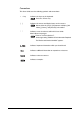
Conventions This User Guide uses the following symbols and conventions: < > key Indicates the keys on the keyboard. Press the key. [ ] Indicates the menus and display items on the screens. Select either the [On] or [Off] buttons to display [Job Name], [Owner], and [Reason] in that order. " " Indicates areas of reference within this User Guide. Also indicates messages. Refer to "3.2 Print Services". A message stating "Additional Port Information Required.
Safety Notes Read these safety notes carefully before using this product to ensure you operate the equipment safely. Your Xerox product and recommended supplies have been designed and tested to meet strict safety requirements. These include safety agency approval, and compliance with established environmental standards. Please read the following instructions carefully before operating the product and refer to them as needed to ensure the continued safe operation of your product.
to be limited or special mitigation measures taken. WARNING Shielded cables must be used with this equipment to maintain compliance with Council Directive 89/336/EEC. The Electricity at Work Regulation (in England and Wales) UK ONLY Electricity at Work Regulations The Electricity at Work Regulation 1989 came into force in England and Wales on the 1 April 1990.
QUESTION: Is Xerox equipment safe? ANSWER: All Xerox equipment supplied by Xerox and their authorized distributors conform to all relevant safety legislation and standards. QUESTION: Is the Xerox equipment in my premises safe? ANSWER: All Xerox equipment supplied by Xerox and its authorized distributors conform to all relevant safety legislation and standards. However, like all electrical equipment, they have to be regularly serviced and maintained by competent persons.
PLEASE NOTE: YOU MUST ENSURE THAT YOUR XEROX EQUIPMENT IS SAFE AT ALL TIMES Electrical Supply This product shall be operated from the type of electrical supply indicted on the product 's data plate label. If you are not sure that your electrical supply meets the requirements, please consult your local power company for advice. WARNING This product must be connected to a protective earth circuit. This product is supplied with a plug that has a protective earth pin.
WARNING - Electrical Safety Information CAUTION Ensure that the power connection for your machine satisfies these requirements • Use only the power cord supplied with this equipment. • The socket outlet shall be installed near the equipment and shall be easily accessible. • Plug the power cord directly into a grounded electrical outlet. Do not use an extension cord. If you do not know whether or not an outlet is grounded, consult a qualified electrician.
Disconnect Device The power cable is the disconnect device for this equipment. It is attached to the back of the machine as a plug-in device. To remove all electrical power from the equipment, disconnect the power cable from the electrical outlet. Operational Safety Information Xerox equipment and supplies have been designed and tested to meet strict safety requirements. These include safety agency examination, approval and compliance with established environmental standards.
• Never remove covers or guards that are fastened with screws. There are no operator serviceable areas within these covers. • Never locate the equipment near a radiator or any other heat source. • Never push objects of any kind into the ventilation openings. • Never override or "cheat" any of the electrical or mechanical interlock devices. • Never operate the equipment if you notice unusual noises or odors.
uct contains lamp(s) with mercury*, and may contain lead*, Perchlorate* and other materials whose disposal may be regulated due to environmental considerations. The presence of these materials is fully consistent with global regulations applicable at the time that the product was placed on the market. For recycling and disposal information, contact your local authorities. In the United States, you may also refer to the Electronic Industries Alliance web site: http://www.eiae.org.
Canadian EME This Class "A" digital apparatus complies with Canadian ICES-003. Cet appareil numérique de la classe "A" est conforme à la norme NMB-003 du Canada. Product Safety Certification This product is certified by the following Agencies using the Safety standards listed. AgencyStandard TUV Rheinland of North America, Inc. UL60950:2000 (USA) Can/CSA-c22.2 No. 60950-00 (Canada) TUV Rheinland Japan Ltd.
Regulatory Information CE Mark The CE mark applied to this product symbolizes Xerox's declaration of conformity with the following applicable Directives of the European Union as of the dates indicated: January 1, 1995: Council Directive 72/23/EEC amended by Council directive 93/ 68/EEC, approximation of the laws of the member states related to low voltage equipment. January 1, 1996: Council directive 89/336/EEC, approximation of the laws of the member states related to electromagnetic compatibility.
Environmental Compliance USA - Energy Star (6030/6050 Wide Format) As an ENERGY STAR partner, Xerox Corporation/Fuji Xerox has determined that (the basic configuration of) **this** product meets the ENERGY STAR guidelines for energy efficiency. The ENERGY STAR and ENERGY STAR MARK are registered United States trademarks. The ENERGY STAR Office Equipment Program is a team effort between U.S.
Canada - Environmental Choice Terra Choice Environmental Services, Inc. of Canada has verified that this product conforms to all applicable Environmental Choice EcoLogo requirements for minimized impact to the environment. As a participant in the Environmental Choice program, Xerox Corporation has determined that this product meets the Environmental Choice guidelines for energy efficiency.
Product Recycling and Disposal USA Xerox operates a world wide equipment take back and reuse/recycle program. Contact your Xerox Sales Representative (1-800-ASK-XEROX) to determine whether this Xerox product is part of the program. For more information about Xerox environmental programs, visit www.xerox.com/environment.
Illegal Copies and Printouts USA Congress, by statute, has forbidden the reproduction of the following subjects under certain circumstances. Penalties of fine or imprisonment may be imposed on those guilty of making such reproductions. 1.
1. Stamps and other representatives of value, of whatever denomination, which have been or may be issued under any Act of Congress. 2. Adjusted Compensation Certificates for Veterans of the World Wars. 3. Obligations or Securities of any Foreign Government, Bank, or Corporation. 4. Copyrighted materials, unless permission of the copyright owner has been obtained or the reproduction falls within the "fair use" or library reproduction rights provisions of the copyright law.
Canada Parliament, by statute, has forbidden the reproduction of the following subjects under certain circumstances. Penalties of fine or imprisonment may be imposed on those guilty of making such reproductions. 1. Current bank notes or current paper money. 2. Obligations or securities of a government or bank. 3. Exchequer bill paper or revenue paper. 4. The public seal of Canada or of a province, or the seal of a public body or authority in Canada, or of a court of law. 5.
Other Countries Copying certain documents may be illegal in your country. Penalties of fine or imprisonment may be imposed on those found guilty of making such reproductions. - Currency notes - Bank notes and cheques - Bank and government bonds and securities - Passports and identification cards - Copyright material or trademarks without the consent of the owner - Postage stamps and other negotiable instruments This list is not inclusive and no liability is assumed for either its completeness or accuracy.
xviii Illegal Copies and Printouts
Table of Contents 1.1 Product Configurations .................................................................................................... 2 1.2 Major Components .......................................................................................................... 4 1.3 Power On/Off ................................................................................................................... 7 1.4 Power Save Mode ........................................................................
Chapter 3 Printer Setup 3.1 Communication Parameters .......................................................................................... 60 Communication Parameters Definitions .................................................................... 60 3.2 Communication Parameter Setup (Printer Control Panel, 6030/6050).......................... 69 3.3 Communication Parameter Setup (Printer Control Panel, 6050A) ................................ 74 3.
Split Drawing ........................................................................................................... 134 Message Option ...................................................................................................... 136 Printed Copy............................................................................................................ 138 Output Option ..........................................................................................................
Print a Diagnostic Report ........................................................................................ 192 4.8 Manual Feed Printing .................................................................................................. 193 Chapter 5 Additional Operations from the Printer Menu 5.1 Introduction.................................................................................................................. 196 5.2 Printer Control Panel Menu (6030/6050).............................
Message List (6030/6050 only) ............................................................................... 249 Chapter 7 Maintenance 7.1 Loading Toner.............................................................................................................. 252 Chapter 8 Problem Solving 8.1 Check the Control Panel(s) ......................................................................................... 256 8.2 Poor Image Quality ................................................................
6
Chapter Chapter 0 1 Product Overview
1.1 Product Configurations The following product configurations and options are available for the Xerox 6030/6050/6050A Wide Format Printer and the Xerox 6030/6050/6050A Wide Format Copier/Printer. Xerox 6030/6050/6050A Wide Format Printer This unit is a printer only. Refer to the printer sections of this guide for information about its setup, features, and usage.
Xerox 6030/6050/6050A Wide Format Printer with Scan System This unit features copier and printer functionality, plus the Wide Format Scan System and the FreeFlow Accxes® Controller. Xerox 6030/6050 Wide Format Printer with Scan System (HFT controller shown is not available with the 6050A) Xerox 6030/6050/6050A Wide Format Options You may acquire additional hardware and software options for all units. Contact your Xerox Sales Representative to obtain additional information on options. 1.
1.2 Major Components Major Components: Front ( *6030/6050 Copier/Printer only ) Name 4 Function *1 Document table Documents to be scanned are inserted here. *2 Setup screen (touch screen) Used to set up copy jobs, map originals to the installed media, display messages and procedures, and provide troubleshooting help, e.g., for jam clearance. *3 Control panel Contains a numeric keypad, Start/Stop buttons, and selection buttons for copy setups.
Name *10 Scanner power switch Function Switches the power to the scanner on and off. Name 1 Toner supply port Function The toner is refilled through this port. Major Components: Rear ( *6030/6050 Copier/Printer only ) Name Function *1 Document ejection port Documents exit the scanner from this location. *2 Power outlet socket Not available 3 Print ejection port Fused copies and prints exit the machine from this location. 1.
Name Function *4 Remote switch A selector switch that enables the user to switch the power to both the scanner and the printer on and off from the Main Power Switch. *5 Interface connector The connector to which the printer is connected. *6 Serial port connector Used by the service representative for maintenance. 7 Circuit Breaker Switch Provides circuit breaker protection for the Copier/Printer or Printer. 8 Paper Heater Switch Switches the paper heaters on and off.
1.3 Power On/Off The scanner and the printer are each equipped with a power switch. The Circuit Breaker Switch must be in the ON position to switch the printer and scanner power on and off. No power is consumed when the Circuit Breaker Switch is in the OFF position, even though the power plug is connected to the power source. Powering On 6030/6050 1 Set the Remote Switch to [Connect].
3 Press power button on Accxes® Controller. The 6050A will not operate unless Accxes controller is ON. Powering Off 6030/6050 Switch off the power following the steps below. Never switch off the power while the machine is printing. Failure to observe this precaution may result in paper jams in the high-temperature areas of the printer. 1 Switch OFF the Main Power Switch.
Powering Off 6050A Switch off the power following the steps below. Never attempt to switch off the power while the machine is printing. Failure to observe this precaution may result in paper jams in the high-temperature areas of the printer. 1 Press the
1.4 Power Save Mode The Power Save Mode automatically lowers the power consumption of the machine by reducing the fuser power. The machine will enter the power save mode when no prints or copies have been made for a preset period of time. • Low power mode 1 This mode reduces the temperature of the fuser, thereby reducing power consumption.
Refer to "3.8 System Parameter Setup (Print Services on Web, 6030/6050)" for changing the power save mode settings from the printer control panel. 1.
1.5 Printer Control Panel Overview Both the Printer and the Copier/Printer versions of the 6030/6050/6050A Wide Format are equipped with a printer control panel. This section provides an overview of this device. Refer to section "2.2 Printer Control Panel Usage" and Chapter 5 for detailed explanations of the use of the printer control panel.
1.6 Print Services on Web Overview (6030/ 6050) Print Services on Web is web server software which is pre-installed in the 6030/ 6050 Wide Format Printer and Copier/Printer. Print Services on Web provides a user-friendly way to perform printer setup, communication (port) setup, job and error log management, and other procedures via a web browser.
Operating Modes User Mode The user mode interface (user page) is shown in the image below. This page displays immediately after a user logs on to Print Services on Web. The selections on the tabs enable the user to do the following. [Job and Log] tab Check the status of a print job. View and print a job log. [Status tab] Check the status of the Printer or Copier/Printer. Start a print job. [Print Setup] tab View the logical printer settings. Refer to section "1.
Administrator Mode To enter the administrator mode, log on to Print Services on Web, select the [Administrator page] button, and then enter the administrator login and password when prompted to do so. The administrator page displays two additional tabs, [Properties] and [Tools], and expands the capabilities of the [Job and Log], [Status], and [Print Setup] tabs. The selections on the Administrator page tabs enable the administrator to perform the tasks listed below.
1.7 Logical Printers Overview (6030/6050) A logical printer (virtual printer) is a group of saved print job settings for a particular data format, i.e., HP-GL, Versatec, TIFF, CALS, and PS/PDF. These saved settings, which are created using Print Services on Web, may include pen attributes, media type, print quantity, and the other parameters that define the print job that the logical printer will be required to perform.
1.8 Loading Roll Media The message ‘Replace xxx media." will display when there is no media loaded or when the roll in use runs out. The media size displayed on the control panel will turn off when there is no media in the machine. Two rolls of media can be loaded in each of the media trays. Refer to the instructions provided in " Setting Up Media" and set up the media parameters after the roll media has been loaded.
3 While pulling on the lever located in the end of the roll paper shaft, remove the paper core in the direction of the arrow. Pulling the lever releases the lock and allows the roll to be removed from the shaft. There is an area at the front of the tray on which the roll paper can be placed. 4 While pulling the lever located in the end of the roll paper shaft, align the roll paper with the paper size marks on the shaft and set the roll in place.
6 Rotate the roll media until the lead edge is gripped in the roller. Rotate the knob until the leading edge of the paper can be seen in the window. 7 Gently but firmly close the media tray. The LED on the front of the tray will illuminate, and the roll paper will feed automatically to its starting position. 8 Set up the media parameters on the copier control panel.
1.9 Drawer Media Size Indicators The media size indictors help the user identify the media that is loaded in each of the drawers. These indicators are visible on the right hand side of the drawers. Usage instructions begin on the next page. The following types are available. • Standard size A • Inch size A Standard size A SB1 Sp.A1 A3 A1 Sp.A2 Sp.
Inserting media size sheets 1 Open the tray. 2 Remove the media size sheet. 3 Fold the sheet so that the size loaded is displayed. 4 Insert the media size sheet. 1.
5 Gently but firmly close the media tray.
1.10 Loading Media for Manual Feeding 1 Adjust the (MSI) Multi Sheet Inserter/ Manual Feed Unit's side guides to fit the size of the media that is to be printed. Set the correct media series for the manual feed sheet. 2 Place the side of the media to be printed face up, and align it with the (MSI) Multi Sheet Inserter/Manual Feed Unit's side guides. • The optional (MSI) Multi Sheet Inserter/Manual Feed Unit is required when making manually fed copies.
1.11 Cutting Roll Media The lead edge of the media should be cut when the media is loaded, on recovery from a media jam, and when the lead edge of the roll is damaged. There are two methods for cutting the lead edge of the roll media: • Automatic cut: This involves making selections on the printer control panel. Refer to the section "5.7 Billing Meter Confirmation (6030/6050)" for the 6030/6050 and "5.
Cutting Roll Media Manually Cutting the Front Roll 1 Open the media tray. 2 Pull the lever to open the tray cover. Lever 3 Rotate the roll media until the lead edge is gripped by the roller. 1.
4 Rotate the knob until the media's lead edge protrudes from the tray outlet. 5 Grasp the cutter by the handle and slide it to the opposite side of the tray to cut the paper. CAUTION: Use the cutter handle to prevent personal injury which may result from sliding your fingers along the sharp, metal cutting bar. 6 Remove the cut off media. 7 Close the tray cover. Window 8 Return the media to its original location by rotating the knob until the lead edge can be seen in the window.
9 Close the media tray. Cutting the Rear Roll 1 Open the media tray. 2 Rotate the roll paper until the lead edge is gripped by the roller. 1.
3 Rotate the knob until the media's lead edge protrudes from the tray outlet. 4 Pull the lever to open the tray cover. 5 Rotate the knob until the paper passes through the tray outlet. 6 Grasping the cutter by the handle, slide the cutter to the opposite side of the tray to cut the paper. CAUTION: Use the cutter handle to prevent personal injury which may result from sliding your fingers along the sharp, metal cutting bar. 7 Remove the media that was cut off. 8 Close the tray cover.
9 Return the media to its original location by rotating the knob until the lead edge can be seen in the window. 10 Close the media tray. 1.
30
Chapter Chapter 0 2 Printer Overview Chapter 2
2.1 Overview of the 6030/6050/6050A Wide Format Printer This section provides an overview of the 6030/6050/6050A Wide Format printer. What is the 6030/6050/6050A Wide Format Printer? The 6030/6050/6050 Wide Format printer processes print jobs that it receives from a client. The 6030/6050/6050A Wide Format printer enables all types of image data to be printed in the supported formats, including standard and nonstandard size documents, enlarged and reduced images, and split (fragmented) images.
Data Formats that can be Processed (6050A) Processing is possible for the following data formats. • HP-GL formats using HP750C emulation (HP-GL2, HP-RTL) • • • • • • • • • • • • • TIFF 6.0 (including LZW) CALS 1&2 CalComp 906/907/951/PCI FileNET NIRS CGM VCGL VRF Versatec Data Standards Xerox Emulation 150 C4 JPEG Optional (Adobe® PostScript® 3™, PDF (1.6), DWF, BMP, JPEG 2000, PNG, GIF, DGN) Communication Interfaces (6030/6050) The following communication interfaces are supported.
Printing Methods (6030/6050) Documents may be submitted from a client to the 6030/6050 Wide Format Printer using any of the following. • Ethernet (Direct) Printing This capability is for UNIX systems. Printing takes place over TCP/IP networks using the ftp and lpr commands. Refer to "Chapter 6 Ethernet Print Service (for UNIX)" for details on available functions.
Printing Methods (6050A) Documents may be submitted from a client to the 6050A Wide Format Printer using any of the following. • Ethernet (Direct) Printing Printing takes place over TCP/IP networks using lpr protocol or raw sockets. Refer to "Chapter 6 Ethernet Print Service (for UNIX)" for details on available functions. • Wide Format Windows Driver / PostScript Driver The Microsoft® Windows® Signed print drivers (32/64 bit) enable users to print documents from various Windows applications.
Print Service Operations The printer control panel and Print Services on Web are the two main features that enable users to set up and perform print service operations.
Print Services on Web (6030/6050 only) Print Services on Web is web server software which is pre-installed in the 6030/ 6050 Wide Format. Print Services on Web provides a user-friendly way to perform printer setup, communication (port) setup, log management, and other procedures via a web browser.
Main Printing Functions This section describes the main printing functions which are available with the 6030/6050 Wide Format Printer and Copier/Printer. Logical Printers (6030/6050 only) A logical (virtual) printer is a group of saved print job settings for a particular data format, i.e., HP-GL, Versatec, TIFF, CALS, and PS/PDF.
• Refer to "3.8 System Parameter Setup (Print Services on Web, 6030/6050)" for details on setting up the logical printer extensions. • Refer to "4.1 Creating a New Logical Printer" for help in setting up logical printers. Document Size Input The following two methods are available for judging the size of the input document: • Automatic Calculates the coordinates of the input document and automatically selects the closest size.
Size Mapping Size mapping is the process of setting up a table that establishes relationships between input document sizes and output image sizes. When size mapping is finished (must be done prior to printing), documents can be enlarged or reduced automatically based on the table entries. A1 Enlarge A2 Input document size A3 Reduce Output image size Refer to " Size/Media Mapping" in "4.3 Logical Printer Print Settings" for more details.
Plot Area, Auto-Layout, and Offset It is possible to print a specified area of an input document. The specified area can be printed in the center of the media or moved to another position (autolayout, offset). Refer to the "Plot Area" section of "4.3 Logical Printer Print Settings" for details on available functions.
Split Drawing (Image Fragmentation) Long images (those that exceed 1,189 mm in length) may be split into several parts and printed. Positioning marks can be added to the split prints for positioning purposes. Refer to "Split Drawing" in "4.3 Logical Printer Print Settings" for more details. Fragment Fragment 1/3 2/3 3/3 Printing the Output Time The date and time a document is printed can be added to the edge of the document. Refer to the "Message Option" section of "4.
Canceling Jobs Jobs transmitted to the 6030/6050/6050A Wide Format can be deleted by pressing the key on the printer control panel. It is also possible to cancel jobs from Print Services on Web. Refer to "2.2 Printer Control Panel Usage" for details on the key, and "4.5 Print Services on Web: Job and Log" for details on Print Service on Web operations. Meter Display The billing meters can be checked from both Print Services on Web (6030/6050 only) and the printer control panel.
2.2 Printer Control Panel Usage This section describes the names and functions of the printer control panel components. [Processing] lamp (green) Indicates the printing status. ON Printing in process Blinking Receiving print data OFF Not printing Printer display Used for setting up the various functions. Displays various messages. [Online] lamp (green) Indicates the data processing status. ON Ready to print. Blinking Moving to the offline mode. OFF The offline mode. Printing is not possible.
Basic Printer Control Panel Operations The printer must be in the offline mode before settings can be changed. Pressing the
Overview of the Operation Menu The printer control panel’s operation menu is depicted in the image below. Descriptions of the sub-menus follow.
PORT SETTING MENU Sets up the communication parameters that are required for connecting to the host. Refer to "3.2 Communication Parameter Setup (Printer Control Panel, 6030/ 6050)" for the 6030/6050 and "3.3 Communication Parameter Setup (Printer Control Panel, 6050A)" for the 6050A for set up procedures. TEST PLOT MENU Prints test patterns to help verify printer operation. Refer to "5.4 Test Printing (6030/6050 only)" for logical printer details and operations.
Operation Examples This section provides examples of how to select menu items.
Setting Up a Value This section provides an example of setting up a value. 1 Select the menu item that you want to set SYSTEM PARAMETER Smoothing < 2 Press the < > key Smoothing ON < up so that it displays on the screen. >< The current value will display. * An asterisk [*] is displayed beside the current value. 3 Use the < > key > and < > keys to change the setting. Smoothing OFF The asterisk [*] will be removed when the setting is changed.
Entering Numbers and Characters This section provides examples of how to enter numbers and characters. 1 Select the menu item that you want to set SYSTEM PARAMETER Low power mode1 < up. 2 Press the < > key Timer Value 05 < >< > key. The current setting for the selected item will * display. 3 Set up the first number using the < > key > and < > keys. The value will increase or Timer Value 15 decrease sequentially between 0 and 9. In the example on the left, press the < > key to display [2].
2.3 Print Services on Web (6030/6050) Print Services on Web is web server software which is pre-installed in the 6030/ 6050 Wide Format. Print Services on Web enables the user to perform the following procedures from a workstation using a web browser.
Starting and Exiting Print Services on Web This section explains how to start and exit Print Services on Web. Start Print Services on Web 1 Start the browser. 2 Enter the URL for the 6030/6050 Wide Format (http://Home name or IP address) in the browser's address field, and then press the key. Exit Print Services on Web 1 To exit Print Services on Web, either click the [¥] button located at the top right corner of the browser, or select [File] > [Exit].
Print Services on Web Organization This section explains the various pages contained within Print Services on Web. User Page This is the first page displayed when connecting with the Print Services on Web. The user page allows users to do the following. [Job and Log] tab Check the status of a print job. View and print a job log. [Status tab] Check the status of the Printer or Copier/Printer. Start a print job. [Print Setup] tab View the logical printer settings.
The administrator page permits the following. 54 [Job and Log] tab • Check the status of jobs in the print queue. • View and print the job log and the error log. • Cancel a print job. • Change the priority of a print job. [Status tab] • Check the status of the Printer or Copier/Printer. • Stop and start print services (job reception and printing). • Stop and start job reception from client computers. • Stop and resume print jobs.
Online Help Click the Help [?] button displayed at the top, right corner of the window to display the online help. The online help enables you to answer many questions related to using Print Services on Web. 2.
2.4 FreeFlow Accxes Web Print Management Tool (6050A) The Freeflow Accxes Web Print Managment Tool (Web Printer Management Tool) is a web-based utility that resides on the controller as a web server. It has the look and feel of a web page even though you are not on the World Wide Web. There are multiple versions of Web Printer Management Tool that are supported on FreeFlow Accxes controllers. The address window uses the URL address, which is the IP Address of the controller you want to access.
Users • • • • View printer status (including media inventory) and the print queue View the printer defaults View the Job Accounting mode for remote print jobs Generate test prints showing configuration data (such as the Controller’s TCP/ IP address) System Administrators with the Password • • • • • • • • Change the priority of, or delete any job in, the print queue Set up all printer defaults Load stamps Specify the Job Accounting mode for remote print jobs Upload controller and printer firmware updates
Using Web Print Management Tool Main Menu The Main Menu contains six selections in hypertext form allowing you to jump to other web pages. Printer Queue Configuration Emulations System Defaults Utilities Help Printer Queue This selection contains 3 tabs for viewing the Job Queue, Mismatched Job Queue and the Active Job Queue. Each Queue lists the Jobs Queued inside the Controller.
Chapter Chapter 0 3 Printer Setup Chapter 3
3.1 Communication Parameters The 6030/6050/6050A Wide Format Printer and Copier/Printer must be connected to a host PC before printing can be performed. Once the Printer or Copier/Printer is connected to the network, the communication parameters must be set up. The communication parameters can be set up from the printer control panel or from Print Services on Web (6030/6050). This section explains how to use both methods to perform the setup procedures.
TCP/IP The communication parameter nomenclature on the printer control panel will sometimes differ from the nomenclature on Print Services on Web (6030/ 6050) or Web Printer Management Tool (6050A). The Print Service on Web and Web Printer Management Tool nomenclature appears in bold type in the table below. The following TCP/IP communication parameters must be set up for the 6030/6050.
\*The ROUTING TABLE can be edited if [Static Routing] is set to [Enable]. A maximum of 512 items can be saved in the routing table. The [Registration Not Possible] screen will display if the number of items exceeds 512. Menu Item 62 Description ROUTING TABLE Select [ADD] to enter additional routing information. Dest. Address Sets the network address for the destination. Enter in the XXX.XXX.XXX.XXX format. Typically not needed. Router Address Sets the router address for the local machine or subnet.
The following TCP/IP communication parameters can be set up for the 6050A using using the printer control panel on the device itself or using the Web Printer Management Tool. Menu Item Description Ethernet Setting Selects the ethernet setting/speed duplex layer. The default setting is [AUTO]. The 6050A is capable of gigabit (1000mbps full duplex) connections, however this is only possible when in [AUTO] mode and when using a CAT6 ethernet cable.
Serial (6030/6050 Only) The serial communication parameters are listed below. The communication parameter nomenclature on the printer control panel will sometimes differ from the nomenclature on Print Services on Web. The Print Service on Web nomenclature appears in bold type in the table below. Menu Item 64 Description Default Parser The default setting is [HP-GL]. Logical printer number Sets up a logical printer number to be use if a logical printer is not defined in the print job.
Menu Item Job Separation (Page limit) 3.1 Communication Parameters Description Sets up the job separation option. The default setting is [NO]. [YES] Starts data conversion once the command that recognizes the end of the data is received, even if it occurs midway through the file. [NO] Spools data on the hard disk until the timeout is issued.
Centronics (optional, 6030/6050 Only) The Centronics communication parameters are presented below. Menu Item Description Ack Mode The Ack mode is selected from [MODE0], [MODE1], [MODE2], [MODE3], and [MODE7]. The default setting is [MODE0]. DMA Timeout The timeout value for data input is entered within a range of 1 to 255 seconds. The default setting is [5 sec]. EOP Timeout Determines if the EOP Timeout will be enabled [TIMEOUT] or disabled [NO_TIMEOUT].
VPI (optional, 6030/6050 Only) The following VPI communication parameters must be set up. Menu Item Description REPORT OFFLINE Determines if the host will be notified offline of the media running out. The default setting is [NO]. [YES] Issues offline notification. [NO] Does not issue offline notification. EOP Timeout Determines if the EOP Timeout will be enabled [TIMEOUT] or disabled [NO_TIMEOUT]. If set to [TIMEOUT], a Timeout Value must be entered.
SNMP (6030/6050 Only) The communication parameters listed below must be set up. SNMP must be set up in Print Services on Web. The communication parameter nomenclature on the printer control panel will sometimes differ from the nomenclature on Print Services on Web. The Print Service on Web nomenclature appears in bold type in the table below. Menu Item 68 Description SNMP Sets whether or not to enable SNMP.
3.2 Communication Parameter Setup (Printer Control Panel, 6030/6050) This section explains the procedures for setting up the communication parameters from the printer control panel. SNMP must be set up from Print Services on Web. The changed parameters become valid after the machine is rebooted. Procedure 1 Press the < MENU PORT SETTING > key with [PORT SETTING] displayed.
1 Display [TCP/IP] on the selection screen, PORT SETTING TCP/IP and then press the < > key. 2 Select the item that is to be set up with the TCP/IP Default Parser use of the < > and < > keys, and then press the < > key. [Ethernet Setting], [Default Parser], [IP Address], [Mask Value], [E-Net Address], [Dynamic Routing], and [Static Routing] will be displayed in that order. • Additions can be made to the routing table when [Static Routing] is enabled.
Static Routing ON Adding items to the routing table * ROUTING TABLE ADD Dest. Address 123. 000. 000. 000 Router Address 123. 000. 000. 000 1. Select [ON] for [Static Routing], and then press the key. Now press the < > key. 2. Select [ADD] for the [ROUTING TABLE], and then press the < > key. 3. Enter the destination address, and then press the key. After setting up the destination address, move the cursor to the right-hand side and press the < > key. 4.
Baud Rate 300 3 Select the parameters with the use of the * < > and < > keys, and then press the key. An asterisk [*] will display on the right side of the parameters once they have been set. Centronics (optional) Setup 1 Display [CENTRO] on the setup item PORT SETTING CENTRO selection screen, and then press the < > key. 2 Select the item that is to be set up with the CENTRO DMA Timeout use of the < > and < > keys, and then press the < > key.
Job Separation YES 3 Select the parameters with the use of the * < > and < > keys, and then press the key. An asterisk [*] will display on the right side of the parameters once they have been set. 3.
3.3 Communication Parameter Setup (Printer Control Panel, 6050A) This section explains the procedures for setting up the communication parameters from the printer control panel. Procedure MENU SYSTEM SETTINGS 1 Press the
3.4 Communication Parameter Setup (Print Services on Web, 6030/6050) The communication parameters for TCP/IP, Serial, Centronics (optional), VPI (optional), and SNMP can be set up from Print Services on Web. These procedures are explained below. • The machine must be rebooted for the changes to take effect. • These procedures are performed in the Administrator Mode. Procedure 1 Start Print Services on Web, enter the Administrator mode, and select the [Properties] tab. Refer to "2.
2 Select the interface or protocol ([TCP/IP], [Serial], [Centro], [VPI], [SNMP]) to be set up from the [System parameters] menu. The setup selections will display in the right-hand pane of the window. In the example below, [Serial] has been selected. • Only standard features and installed options are listed in the [System parameters] menu. [VPI] and/or [Centro] will be listed if one or both of these options is installed. • Refer to the section " Communication Parameters Definitions" in "3.
4 To print a list of the settings, drag the right scroll bar to the bottom, and then select the [Print] button. 5 After setting up all of the parameters, switch the Main Power Switch off and then on to enable the changes to take effect. 3.
3.5 Communication Parameter Setup (Web Printer Management Tool, 6050A) • Consult Web Printer Management Tool help system for details on communication parameter setup of the 6050A.
3.6 System Parameter Setup (Printer Control Panel, 6030/6050) The following system parameters can be set up from the printer control panel. These parameters can be set up on the copier control panel on the Xerox 6030/6050 Copier/Printers. If the parameters are set up on both the printer control panel and the copier control panel, the most recent settings will take precedence. • Refer to "2.2 Printer Control Panel Usage" for detailed instructions on printer control panel operations.
Menu Item Description Sleep Mode Sets the sleep mode to [ON] or [OFF] and sets the time (15 to 120 minutes) that must elapse after the previous copy or print job until the machine enters the sleep mode. The sleep mode switches off the power of the printer. The default setting is [90] minutes. Attention Light Not Available Buzzer Not Available Print Density Sets up the default print density level. The density setting is a numeric value between -99 and 99.
[Sleep Mode], [Attention Light], [Print Density], [Job Recovery], and [Net Cont. Time] will display, in that order.. Press the < Job Recovery OFF > key to select the item. 3 Select the parameters using the < * < > and > keys, and then press the key. An asterisk [*] will display on the right side of the value once it is set. The changed parameters are saved to the system when the key is pressed. It is not necessary to save each change individually. 3.
3.7 System Settings Setup (Printer Control Panel, 6050A) The following system parameters can be set up from the printer control panel. • Refer to "2.2 Printer Control Panel Usage" for detailed instructions on printer control panel operations. Menu Item Description TCP/IP Allows the entering of an IP Address, IP Subnet Mask and an IP Gateway address. Also allows DHCP and RARP/BOOTP to be enabled or disabled. Date/Time Sets up the internal clock.
6050A Printer Control Panel Example Procedure MENU SYSTEM SETTINGS SYSTEM SETTINGS TCP/IP 1 Press the < > key with [MENU]/[SYSTEM SETTINGS] displayed. 2 Scroll to the item you wish to set up using the < > and < > keys. [TCP/IP], [Date/ Time], and Timers will display, in that order. Press the < > key to select the item. In this instance, choose [TCP/IP]. DHCP Enable* 3 Select the parameters using the < < > and > keys, and then press the key.
3.8 System Parameter Setup (Print Services on Web, 6030/6050) The system parameters listed below can be set up from Print Services on Web. These procedures are performed on the Administrator page. Refer to "3.4 Communication Parameter Setup (Print Services on Web, 6030/6050)" for information about setting up the [TCP/IP], [Serial], [Centro], [VPI], and [SNMP] selections in the [System Parameters] menu on the Properties tab.
Menu Item Job Recovery Description Determines how the jobs that were in the print queue when the printer power was shut off will be processed when the printer is switched back on. The default setting is [OFF]. [OFF] Jobs that had not been output when the power was shut off are canceled (not printed). [QUEUED] Prints out only the [Queued] jobs waiting to be processed. [ALL] Prints out all jobs that have not been successfully completed.
2 Select the item that is to be set up from the [System parameter menu], for example, [Priority], [Replot], [Print density], [Paper Width for Special A], [Job Recovery], [Exclusive access time out], [Extension], and [Set date]. Setting Up [Priority] The [Priority] parameter in Print Services on Web is the same as the [Print service] parameter on the printer control panel. 1 Select [Priority] from the [System parameters] menu. The [Priority] selections will display in the right pane.
3 Press the [Apply] button to save the new setting, [Cancel] to revert to the existing setting, or [Reset to default] to return to the factory default setting. Setting Up [Replot] 1 Select [Replot] from the [System parameters] menu. The Replot setup selections will display in the right pane. 2 The parameter is enabled by default. De-select the checkbox to disable the feature. Disabling the feature will render the reprinting function inoperative.
2 Enter a positive or a negative number between -99 and +99 to set up the default print density. Larger negative numbers lighten the prints. Higher positive numbers darken the prints. The factory default setting is [0]. 3 Press the [Apply] button to save the new setting, [Cancel] to revert to the existing setting, or [Reset to default] to return to the factory default setting. Setting Up [Paper Width for Special A] 1 Select [Paper Width for Special A] from the [System parameters] menu.
2 Select the required paper width for Special A1 and Special A2 paper from the available selections. 3 Press the [Apply] button to save the new setting, [Cancel] to revert to the existing setting, or [Reset to default] to return to the factory default setting. Setting Up [Job Recovery] 1 Select [Job Recovery] from the [System parameters] menu. The Job Recovery selections will display in the right pane.
2 Select the required format from [Data format]. 3 As required, add or delete an extension: Add an extension To add a new extension, enter an extension name of eight characters or less in the text field, and then click the [Add] button. Delete an extension To delete an extension, click the [Delete] button. Click [OK] or [Cancel] on the warning popup to confirm or cancel your selection.
2 Enter the date. If the time selections are not displayed, drag the bottom scroll bar to the right to display them. 3 Enter the time. 4 Press the [Apply] button to save the new setting, or press [Cancel] to revert to the existing setting. 3.
3.9 System Parameter Setup (Web Printer Management Tool, 6050A) • Consult Web Printer Management Tool help system for details on setting up system parameters for the 6050A.
3.10 Printing a Configuration List (6030/ 6050) The procedures below explain how to print a configuration list that shows the hardware and software configuration, communication parameter (port) settings, and system parameter settings of the printer. This list may be printed from either the printer control panel or Print Services on Web. From the Printer Control Panel MENU PORT SETTING PORT SETTING PRINT CONFIG PRINT CONFIG SET: to Print. 1 Press the < > key with [PORT SETTING] displayed.
2 Select [Print Settings] in the System parameters menu. The current print settings will display in the right pane. 3 Using the scrollbar on the right side of the window, scroll to the bottom of the Print Settings list, and then select the [Print] button. The printer will print a configuration list that is identical to the list from the printer control panel.
An example of the configuration list (settings printout) is shown below. 3.
Description of the Configuration List Contents The contents of configuration list are explained below. Displayed Item H/W CONFIG S/W CONFIG PORT SETTING SYSTEM PARAMETER 96 Description Model Product name Software Version Installed version of the printer software RAM Total Displays the amount of memory installed in the printer. Segment Memory Displays the capacity of the area where spooled print data is stored during print processing.
3.11 Printing a Configuration List (6050A) The procedures below explain how to print a configuration list that shows the hardware and software configuration, communication parameter (port) settings, and system parameter settings of the printer. This list may be printed from either the printer control panel or Web Printer Management Tool. From the Printer Control Panel 1 Press the < MENU UTILITIES > key with [UTILITIES] displayed.
2 Select the [Test Print] sub-tab that appears. 3 Depending upon your information requirements, click on the [Minimal], [Normal], [Full], or if PostScript is available, [PostScript] test print buttons. Explanations of each of these options are available from the Web Printer Management Tool interface.
An example of the configuration list (settings printout) is shown below. 3.
Description of the Configuration List Contents The contents of the configuration list are explained below. Category Description Controller Configuration Displays data such as controller date/time, firmware version, size of hard disk, etc. Optional Controller Features Displays which optional features of the 6050A have been activated. Print Engine Configuration Displays data such as the set resolution of the 6050A, power saver information, and the IOT error log.
3.12 Software Option (Print Services on Web, 6030/6050) The [Software Option] selection on the Print Services on Web [Properties] tab displays all installed optional software and related Feature Key (Key Install Key) information, for example, for the PostScript Driver. 3.
3.13 Software Option (Web Printer Management Tool, 6050A) Similar to the [Software Option] selection under the Print Services on Web [Properties] tab, the the [Features] selection under the [Configuration] tab in Web Print Management Tool allows for the display of what features are currently installed on the 6050A.
3.14 Change Password (Print Services on Web, 6030/6050) The [Change Password] selection on the Print Services on Web [Properties] tab can be used to change the password that is used to log in to the Administrator page. Maintain a record of the new password in a secure location. 1 Select the [Change Password] selection on the [Properties] tab. The [Change Web administrator password] fields will display in the right pane of the window. 2 Enter the current password in the [Current password:] field.
3.15 Change Password (Web Printer Management Tool, 6050A) Maintain a record of the new password in a secure location. 1 Select the [Utilities] tab on the main navigation bar, then click on the [Password] sub-tab. 2 Enter the current printer password in the [Enter the current printer password:] field. 3 Enter the new password in the [New printer password:] field. 4 Enter the new password again in the [...and again to verify:] field. 5 Click on the [Update Printer] button to activate the new password.
3.16 Change Default Language (Print Services on Web, 6030/6050) The [Change default language] selection on the Print Services on Web [Properties] tab can be used to change the language that is displayed when Print Services on Web is started. The language can be changed to English, French, Italian, German, Spanish, or Portuguese. This setting becomes effective after the machine is switched off and then on again. 1 Select the [Change default language] selection on the Print Services on Web [Properties] tab.
3.17 Change Default Language (Web Printer Management Tool, 6050A) Web Printer Management Tool allows the user to change the language displayed when it is started. The language can be changed to English, Italian, French, Spanish, South American Portuguese, German or Russian. 1 Select the [Configuration] tab on the main navigation bar, then select the [Printer] sub-tab. 2 Under [Printer Setup], click to the right of the [Printer Language] text and choose the required language.
Chapter Chapter 0 4 Logical Printer Setup and Operation (6030/6050 only) Chapter 4
4.1 Creating a New Logical Printer One hundred logical (virtual) printers, numbered from 00 to 99, can be set up for each of the available data formats (HP-GL, Versatec, TIFF, CALS, PS/PDF). The procedure below explains how to create a new logical printer. 1 Start the web browser and log in to Print Services on Web. 2 Enter the Administrator mode, and then select the [Print Setup] tab.
3 Select the data format for the new logical printer from the [Data format] menu. The selections include [Versatec], [HP-GL], [TIFF], [CALS], and optionally, [PS/PDF]. The logical printers are pre-configured in the factory to their default print settings. These defaults, as well as the options you can select, are defined in the upcoming section "4.2 Defining the Print Settings". When you display a list of logical printers, as in step 4, the current print settings will display.
4 Select an unused logical printer. To do this, select a range of numbers in the [Detail] list at the left side of the screen, beginning with [00-09]. The ten logical printers will appear in the right pane of the screen. 5 Continue selecting the ranges of numbers, as required, until you locate an unused logical printer, and then click the [Display] button. The default print settings for the selected data format and logical printer will display in the [Logical printer information...
4.2 Defining the Print Settings The next step, after creating a logical printer, is to set up the parameters that define how it will process print jobs. These parameters are located at the left side of the screen in the [Print Setup] menus ([Media setting], [Input setting], [Output setting], [Transform], [Pen setting], and [Command setting]). 1 Click an item in a [Print Setup] menu to display the available selections. The settings for the selected item will display on the right side of the screen.
4.3 Logical Printer Print Settings This section describes the print settings for the logical printers. Logical Printer Parameters by Data Format The logical printer parameters will vary by data format, as indicated in the table below.
[Print Setup] Menu Media setting (continued) Menu Item Media Source Description Format Determines whether the paper is to be fed automatically from a roll or from the (MSI) Multi Sheet Inserter/Manual Feed Unit, and sets up the priority ([Job] or [Controller]). All The optional (MSI) Multi Sheet Inserter/Manual Feed Unit is required for manual feeding. Media Type Input setting Output setting Transform Sets up the media type ([Any], [Bond], [Vellum], [Film]).
Parameters Unique to Data Formats [Print Setup] Menu Output setting Pen setting Command setting Menu Item Data Format Plot Area Sets the print range, centering, and offset. All (see Note) Color Option Enables or disables the White Mode (white line) function. HPGL, Versatec TIFF Option Sets up the sorting and output sequence, and the resolution for the print data. TIFF CALS Option Sets up whether or not to disable the [ROTATE] command.
Media Series This parameter sets up the media size series for the input size, output size, and media size. Each item can be set to a different media size series. Settings The settings are as follows. All of the default settings are [ISO A]. Menu Item Description Input size Sets up the media group for determining the input size. The selections available are [ISO A series], [Special A series], [ARCH series], [ISO B series], [ANSI series], and [ARCH-30 series].
The media types that can be set for each paper group are shown below.
Size/Media Mapping Standard size images and user-defined images can be enlarged and reduced to fit standard and user-defined output sizes. This is known as "Size Mapping". It is also possible to specify which roll media is to be used based on the output size. This function is known as "Media Mapping". The function that automatically determines the output media size that best matches the size of the output image is known as "Auto Mapping".
A3 A3 Output image size Paper Rotated 90 degrees Settings A3 Output on the A3 roll media Output on the A2 roll media The settings for this function are as follows. Menu Item Description Auto Mapping Sets whether the automatic mapping functions is to be enabled or not. The output paper size that best matches the output image size will be determined automatically when this function is set to [Enable]. The values specified in paper mapping will be invalidated.
Example When the mapping table is set up as shown below, an image with an input size of A3 will be printed as follows. d Media Mapping Input size Output size Media size A0 A0 A0 A1 A1 A1 A2 A1 A1 A3 A2 A2 A4 A4 A4 c Size Mapping c Size mapping is applied to the image with an input size of A3, which is then enlarged to an A2 output size (enlarged by 141.4%).
Media Source This setting determines whether the media will automatically feed from a roll or from the manual feed tray (cut sheet). The priority sequence when automatic selection is specified is [Roll1], [Roll2], [Roll3], and [Roll4], in that order. The optional (MSI) Multi Sheet Inserter/Manual Feed Unit is required for manual feeding. Settings The settings for this function are as follows. Menu Item Description Media Source [AUTO] Automatically selects the appropriate media from the feed trays.
Media Type Determines the default media type selection for printing. This setting is valid when a different type of media of the same size is loaded in the printer. [ANY] is set for this under normal circumstances. When the media type specification command is already set up in the job data from the host, the host command has priority. Settings The settings for this function are as follows. Menu Item Media Type 4.3 Logical Printer Print Settings Description Selects the media for printing.
User-Defined Size The user-defined sizes are used for printing long images and non-standard size media. User-defined sizes can be specified for each standard size. It is possible to uniformly output all images that exceed the standard sizes but are within the specified user-defined sizes. The user-defined sizes are only valid when the [Paper Size] selection on [Output Option] is set to [AUTO]. Settings The settings for this function are as follows.
Input Option Sets up the input image size. Two judgment methods are available for input image size. • Automatic (AUTO) Calculates the coordinates of the input image and automatically determines the nearest media size. • Specify Size Enables the user to manually select the media size of the input image. The media size can be selected from standard sizes and user-defined sizes. This option is usually set to [AUTO].
Menu Item Description Number of Fragments Sets up the number of copies to be printed consecutively in a range from 0 to 99 when [Size] has been set to [AUTO]. The default setting is [1]. A value that subtracts 1 from the length of the standard size will be set for [Connect]. For example, in the event of 4A3, 3 will be set for the [Connect]. Refer to the section on "Media Series" for further details on paper groups.
Input Size Margin Specifies the top, bottom, left, and right margin settings for determining input sizes. Plus (+) values represent margins outside of the media size, and minus (–) values represent margins inside the media size. The size that includes (excludes) these margins is established as the input judgment size. These settings are only valid when the [Input Options] - [Size] parameter is set to [AUTO].
The settings for this function are as follows. Menu Item Description X Sets the left and right margin values within a range of –99 to 99 mm. The default settings is [5 mm]. Y Sets the lead and trail margin values within a range of –99 to 99 mm. The default settings is [5 mm]. Example The media margin settings are determined according to the following for input data consisting of 300 x 420 mm.
Plot Area Enables the print range (the plot area) to be specified based on the input image information. The plot area can be set up so that the image prints in the center of the media (Auto Layout) or is offset (Set Offset Value). If part of the image overlaps the margin when offset is specified, it will be cut off. Auto layout Plot Area +Y direction Offset = (_X, +Y) _ X direction +X direction _ Y direction Input image Output image 4.
Settings The settings for this function are as follows. The plot area cannot be set up for TIFF and CALS data. Only the auto layout function can be set for them. Menu Item Area Mode Description Sets the range to be printed at [ADAPTED], [FIXED], [IP], [IW], [RASTER], or [FIRST]. The default setting is [ADAPTED]. See the next page for more details. •[IP] and [IW] can be set for HP-GL data only. •[RASTER] can only be set for HPGL data if the [PS COMMAND] has been set to [Ignore].
in the Y direction. Size OFFSET X (–999 to 999) Y (–999 to 999) A0 0 mm 0 mm A1 –10 mm 10 mm A2 20 mm 10 mm A3 0 mm 0 mm A4 0 mm 0 mm Descriptions of Area Mode The area modes are described below. ADAPTED The data range of the input image is set as the print range (see Fig.1). FIXED (HP-GL) The range that encloses the maximum coordinate of the input image and the coordinates that represent the starting point of that coordinate is set as the print range.
Fig.1. (ADAPTED) Input image (0,0) Offset Output image Auto Layout: [YES] Auto Layout: [NO] Fig.2. (FIXED) (+X1,+Y1) Input image Offset (0,0) Output image Auto Layout: [YES] Auto Layout: [NO] Fig.3. (IP AREA and IW AREA) The area specified with the [IP Command] or [IW Command].
Fig.4. (FIRST) (0,0) Output image Offset Auto Layout: [YES] Auto Layout: [NO] Fig.5. (FIRST) (0,0) Input image 4.
Priority Sets up the printing priority. This function increases the priority of a job to print it out sooner when the job queue is congested. Settings The settings for this function are as follows. Menu Item PRIORITY 132 Description Sets one of the following as the printing priority. The default setting is [NORMAL].
Title Block The setting determines whether or not to rotate images 180 degrees. This setting is used to change the image orientation to ensure correct folding. Settings The available settings are as follows. Menu Item Description Media Size Determines whether or not to rotate images for each media size. Displays the media sizes that are selected in [Output size] under [Media series]. Title Block The setting determines whether or not images will be rotated. The default setting is [Last].
Split Drawing When an image exceeds 1,189mm in length, it can be split (fragmented) and printed in sections. This function also enables you to add positioning marks on each split section. A maximum of 30 such sections is possible. Fragment length Fragment length 1/3 2/3 3/3 Settings The settings for Split Drawing are as follows. Item 134 Description Split drawing mode Set to either [Do not split] or [Split]. The default setting is [Do not split].
Item Description Page margin Determines whether or not the page margin will be present, and sets the margin where the pages are joined within a range of 0 to 90 mm. The default settings is [0 mm]. Alignment mark printing Determines whether or not to print positioning marks. The default setting is [OFF]. 4.
Message Option Determines whether or not to print error messages, label messages, and date messages on the print. The size of the characters used in the messages is fixed at a height of 2 mm regardless of the enlargement or reduction. 5 mm Top left 2002/04/23 14:56 2002/04/23 14:56 5 mm Bottom left Top right 5 mm 2002/04/23 14:56 2002/04/23 14:56 Bottom right 5 mm Settings The settings are as follows. Menu Item 136 Description Error Message Determines whether or not to print error messages.
Menu Item Description Date Message Determines whether or not to print date messages. The default setting is [OFF]. The date format is [Year/Month/Day Hour:Minutes]. Example: [2006/01/02 14:56] Display Position Sets up the location where the message(s) will be printed. [Upper left] Prints the message(s) at the top lefthand corner of the page. [Lower right] Prints the message(s) at the bottom right corner of the page. [Lower left] Prints the message(s) at the bottom left corner of the page.
Printed Copy Sets up the default number of copies to be printed. Settings The settings for this function are as follows. The [Priority] parameter can only be set for Versatec data. Menu Item 138 Description Printed Copy Sets up the number of copies to be printed, in a range from 1 to 99. The default setting is [1]. Priority [JOB] The copy count command in the job data takes priority. [Controller] The setting made on the printer control panel takes priority. The default setting is [JOB].
Output Option Sets up the output size. The following two judgment methods are available for output image size. • Automatic (AUTO, OTHER, MIX, MIX2) Determines the most suitable output size based on the input size and the size mapping table. It also determines the roll media size to use based on the output size and the media mapping table (or automatically.) • Specify Size Enables the media size of the input image to be entered directly.
Settings The settings for this function are as follows. Menu Item Media Size Description This parameter can be selected from [AUTO], [OTHER], [MIX], [MIX2], or any of the standard media sizes. The default setting is [AUTO]. [AUTO] The standard shape priority mode. If the length of the document exceeds the standard size, the media is cut to the standard shape that has been increased in length. [OTHER] Synchronized cutting is performed on all images.
• Media Size In the case of [AUTO] Output in a size that is the standard shape increased in a multiple of integers. Input image that is longer than the standard size In the case of [OTHER] The same size as the input image is output. Output image • • Connect Margin 4A3 Top margin A3 A3 A3 A3 Paper feed direction Bottom margin Connect = 3 4.
Size Recognition Size recognition determines whether images that are less that an A0 size in length (1,189 mm), but that are larger than a standard size, will be printed on media that is one size larger, or on standard size that has been increased in length. This setting is useful when all images will be printed on the same standard size media or on a standard size that has been increased in length. This setting is only valid when the [Paper Size] selection for [Output Option] is set to [MIX].
The settings for this function are as follows. Menu Item Description Size Sets up the size recognition priority mode. Recognition The default value is [Standard long size output]. 4.3 Logical Printer Print Settings [Standard long size output] Outputs images that are within the A0 size, but exceed the standard size, on one size larger standard shape paper.
Color Option Sets the pen drawing color at a specified density or at black when a color command other than black is specified. This setting is only valid for HP-GL and Versatec data. Settings The settings for this function are as follows. Menu Item White Mode 144 Description Determines how lines will be drawn when the image information specifies a color other than black. [ENABLE] Draws lines with pens of varying densities that correspond to the specified colors.
Transform Enables or disables the auto scale (automatic enlargement/reduction), mirror image, and 90-degree rotation functions. Auto Scale Input image Output image Mirror Image Input image 4.
90-degree Rotation Output image Input image Settings The settings for this function are as follows. Menu Item Auto Scale Description Determines whether or not to automatically enlarge or reduce sizes when the input size and output size are different. The default setting is [ENABLE]. [ENABLE] Automatically enlarges or reduces the size of the image to match the output size. [DISABLE] Outputs the image at the same size regardless of the output size.
Define Single Pen Defines the width, color, end style, and joint style pen attributes for HP-GL data. Click the [Change] button to edit the attributes of a pen. The screen below will display. Click [Apply] to save your changes. Settings The settings for this function are as follows. Menu Item Pen No. 4.3 Logical Printer Print Settings Description Sets up the pen number, in a range from 0 to 98.
Menu Item Width Description Sets the line width in a range from 0 to 511, where a setting of 1 = 0.0635 mm. The actual width of the line will be n × 0.0635, with the line width set to n. The default setting is [2]. Lines may be printed in patches if the width is set to [1]. Color Sets the line color to [BLACK] or [WHITE]. The default setting is [BLACK]. End style Sets the end of the line to [SQUARE], [ROUND], [EXTEND], or [TRIANGLE]. The default setting is [SQUARE].
SQUARE The normal method for ending lines. ROUND Rounds off both ends of the line with a half radius of the line width. Line width Half the line width Half the line width EXTEND Extends both ends by half the line width. Line width Half the line width Half the line width TRIANGLE Adds a triangle that is half of the line width in length to both ends of the line. Line width Half the line width Half the line width Joint style 4.
UNJOINT Does not join the lines. BEVEL Joins the outside corner of one line to the outside corner of the other line. MITER Extends the outside corners of both lines until they meet in a miter. ROUND Rounds off the area where the two lines meet. TRIANGLE Extends the joint by half the line width, and connects the top and outer edges of both lines. MITERED/BEVELED Extends the joint by the length calculated from the line width and Miter Limit, and connects the top.
Define Multi Pen Sets up the line width, color, end style, and joint style pen attributes for HP-GL data for multiple pens. The same parameters will be set for all other pen numbers within the specified range. Settings The settings for this function are as follows. Menu Item Description Pen No. Specifies the starting number and the ending number that cover the range of pens that are to be set up. The pen numbers are set within a range of 0 to 98.
Pen Option Determines whether or not to change the ratio of the pen thickness based on the enlargement/reduction ratio. This setting is valid for HP-GL data and Versatec data only. Settings The setting for this function is as follows. Menu Item Description Enlarge/reduce [ENABLE] pen width [DISABLE] 152 Changes the pen width based on the enlargement/reduction ratio. The pen width remains unchanged. The default setting is [DISABLE].
Emulation Selects the processing language for the HP-GL format only. Settings The settings for this function are as follows. Menu Item Emulation 4.3 Logical Printer Print Settings Description Sets the processing language at either [HP-GL] or [HP-GL/ 2]. The default setting is [HP-GL].
PS Command Enables or disables the PS command. These settings are valid with HP-GL data only. Settings The available settings are as follows. Menu Item PS command 154 Description [DO NOT IGNORE] Enables the PS command. [IGNORE] Disables the PS command. The default setting is [DO NOT IGNORE].
EOP Command Enables and disables the EOP command for HP-GL data only. Settings The settings for this function are as follows. The default value for all parameters is [Enable]. Menu Item Description SP:Pen0 Enables or disables the SP:Pen0 command. PG:Adv Page Enables or disables the Adv Page command. NR: Enables or disables the NR command. FR: Enables or disables the FR command. AF: Enables or disables the AF command. AH: Enables or disables the AH command. 4.
VCGL Pen Style (VCGL Define Pen) Sets up the pen specifications for VCGL data only. Settings The settings for this function are as follows. Menu Item Joint style Description Sets up the joint processing for lines to [UNJOINT], [BEVEL], [MITER], or [ROUND]. The default setting is [UNJOINT]. Refer to "Joint style" for further details. This setting is only valid when printing poly-lines, polygons and rectangles. End style Sets the end of the line to [SQUARE], [ROUND], [EXTEND], or [TRIANGLE].
Example Dot Broken line style NO WRAP Each dot represents the start of the broken line. Lines printed with the use of the broken line style shown in the example will be printed as a non-broken line, as shown in the illustration on the left. This is due to the fact that the dot appears before the line is broken, and this constitutes the starting point for printing another line. WRAP Each dot represents the direction in which the broken line must be printed.
VCGL Pen Width Sets up the width of the VCGL pen only. Settings The setting for this function is as follows. Menu Item Width Description Sets the line width in a range from 0 to 511. 1 = 0.0635 mm. The actual width of the line will be n × 0.0635, with the line width set to n. The default setting is [2]. Text may not print clearly if the line width is set to [1].
VRF Define Pen (Define Single Pen) Sets the pen attributes for VRF data only. Click the [Change] button to define the attributes for a pen. The VRF Define Pen menus will display on the right side of the screen. Settings The settings for this function are as follows. Menu Item Description No. Sets the pen number within a range of 0 to 31. Width Sets the line width in a range from 0 to 511. 1 = 0.0635 mm. The actual width of the line will be n × 0.0635, with the line width set to n.
Menu Item Description End style Sets the end of the line to [SQUARE], [ROUND], [EXTEND], or [TRIANGLE]. The default setting is [SQUARE]. Refer to "End style" for further details. Color Sets the line color to [BLACK] or [WHITE]. The default setting is [BLACK]. Although it is also possible to set the [Width] from Print Services on Web, the width data included in the VRF data take priority, and any changes on the Print Services on Web screen will have no effect on the output.
VRF Define Multi Pen Sets the pen attributes for multiple pens for VRF data only. The same parameters will be set for all other pen numbers within the specification range. Settings The settings for this function are as follows. Menu Item Description Pen No. Specifies the starting number and ending number that cover the range of the pens that are to be set up. The pen numbers are set within a range of 0 to 31. Width Sets the line width in a range from 0 to 511. 1 = 0.0635 mm.
TIFF Option Sets up the sorting and output sequence, and the resolution priority for TIFF data. These settings are only valid with TIFF data. Settings The settings for this function are as follows. Menu Item 162 Description Sort mode Determines whether or not to sort the output data. The default setting is [DISABLE]. [ENABLE] Sorted. [DISABLE] Not sorted. Last to first Determines whether or not to print in the reverse order. The default setting is [DISABLE]. [ENABLE] Prints in the reverse order.
CALS Option Determines whether to enable or disable the [Rotate] command for CALS data only. Settings The settings for this function are as follows. Menu Item Specify Output Direction 4.3 Logical Printer Print Settings Description [ENABLE] Enables the [Rotate] command. [DISABLE] Disables the [Rotate] command. The default setting is [DISABLE].
PS/PDF Option The available selections set up the default media size, roll, and DMS for PS/PDF data. Settings The settings for this function are as follows. Menu Item 164 Description Default Media Size If media size information is not included in the print data, and no media is loaded in any trays, the page size of the data will be the selected media size. The default setting is [ISO_A0].
4.4 Logical Printer Operations This section explains the procedures for performing the following using Print Services on Web. • Selecting the Media Type • • • • • Using Media Other Than the Default Series Changing Output Roll Media for an Entire Job Reduction and Enlargement Using Size Mapping Printing Long Documents Print Services on Web: Job and Log 4.
Selecting the Media Type The media type for the logical printers is set up using the [Media Type] selection. The available selections include [Any], [Bond], [Vellum], and [Film]. [Any] typically is selected as the media type. Specify the media type manually if the media is limited to a particular type. If a media other than the specified type is loaded after this setting is made, a [No Paper] error will be triggered. Refer to "4.3 Logical Printer Print Settings" for details.
Using Media Other Than the Default Series The media size series is set up using the [Media series] selection. The available selections include [ISO A series], [ISO B series], [SP. A series], [ARCH series], [ANSI series], and [ARCH-30 series]. The [Input size], [Output size], and [Media size] parameters can be set up individually for each media group. • [Input size] is the group used when judging the input size. • • [Output size] is the group used when judging the output size.
Changing Output Roll Media for an Entire Job By setting the [Output Option] [Size] selection to [AUTO], the output media is determined by the settings in the logical printer's [Media mapping] table. If a media mapping table is prepared for each job, the output roll media can be changed for each job.
Reduction and Enlargement Using Size Mapping Reduction and enlargement can be performed using the size mapping table. The size mapping table establishes relationships between input image sizes and output image sizes. It enables users to enlarge or reduce prints automatically. The size mapping table is set up using the logical printer’s [Size/media mapping] selection. [Auto scale] is set to [Enable] and [Media size] (on [Output Option]) is set to automatic ([AUTO], [OTHER], [MIX], or [MIX2]).
Printing Long Documents The media cut mode can be set to either the standard A0 format (1,189 mm), the standard shape increased in length, or the synchronized cut. This parameter is set up using the logical printer [Output Option] feature. [AUTO] : The standard shape priority mode. If the length of the document exceeds the standard size, the paper is cut to the standard shape that has been increased in length. [OTHER] : Synchronized cuts performed on all images.
4.5 Print Services on Web: Job and Log The Print Services on Web [Job and Log] tab enables the user to perform the following. • Display the Print Queue • • Cancel and Change the Priority of Jobs Manage the Job and Error Logs • The Print Services on Web [Help] function provides step-by-step instructions for performing many of the tasks described below. It also lists and describes the items and fields that appear on the screens.
2 Select [Job not completed]. A list of print jobs will display on the right side of the window. If the Administrator page is displayed, the jobs that are waiting to print will display a [Change] link at the right side. A job that is printing can not be changed, that is, it can not be canceled or be assigned a different priority.
Displayed Item Description Printer Name Displays the name of the destination logical printer. [---] is displayed when the name is unknown. Size Displays the size of the job in KB. Change Job Changes the priority of or cancels a job. (On the Administrator page only) 4.
Cancel and Change the Priority of Jobs Use this procedure to cancel a print job or change its priority. • These procedures can only be performed from the Administrator Page. • Completed jobs cannot be canceled or have their priority changed. Procedure 1 Start Print Services on Web, log on as Administrator, and select the [Job and Log] tab. Refer to "2.3 Print Services on Web (6030/6050)" for details on starting up Print Services on Web. 2 Select [Job not completed].
To reduce the size of the list, set up the [Logical printer] and [Logical printer number] fields, and then click the [Update] button. Set the [Update time] to automatically update the list, if desired. 3 Click the [Change] link located on the right side of the job that you want to cancel or change. The [Change job] page will display. 4 To cancel the job, click the [Execute] button.
Manage the Job and Error Logs This function allows the user to print and delete the Job Log and the Error Log. It is only possible to display a list of jobs on the User page. All other operations must be carried out on the Administrator page. Job log and error log management also can be performed from the printer control panel. Refer to "5.5 Managing the Job and Error Logs (6030/6050 only)" for more information. Job Log The job log is a record of all completed print jobs.
2 Select [Job Log] from the [Log list] menu. A list of processed jobs will display on the right side of the screen. To display a subset of the logged print jobs: •Enter a range in the [Job number] fields, and then click the [Update] button - or •Enter the inclusive dates in the [Print log from:] fields, and then click the [Update] button. A list of the specified jobs will display. Use the [Date] menu to sort the jobs in either ascending or descending order by date.
178 Chapter 4 Logical Printer Setup and Operation (6030/6050 only)
2 Select [Job log] from the [Log list] menu. A list of completed jobs will display on the right side of the screen. To display a subset of the logged print jobs, enter a range in [Job number] or specify the period in the [Print log from:] fields, and then click the [Update] button. The list of the specified jobs will display. 3 Click the [Print] button. Print the Job Log (automatically) 1 Start Print Services on Web, log on as Administrator, and display the [Job and Log] tab. 4.
2 Select [Job Log] from the [Log list] menu. A list of log information will display in the right pane.
3 Click [Change settings]. The [Job log setup] screen will display. 4 Select [ON] as the [Auto Print Setup] selection, and then click [Apply]. The job log will print automatically whenever sufficient job log entries accumulate. Delete the Job Log 1 Start Print Services on Web, log on as Administrator, and display the [Job and Log] tab. 2 Select [Job Log] from the [Log list] menu. The job log will display in the right pane. 4.
182 Chapter 4 Logical Printer Setup and Operation (6030/6050 only)
3 Click the [Delete log] button. A confirmation popup will display. 4 Select the [OK] button to delete the job log, or [Cancel] to retain the log. Save the Job Log 1 Start Print Services on Web, log on as Administrator, and display the [Job and Log] tab. 2 Select [Job Log] from the [Log list] menu. The job log will display in the right pane. 4.
184 Chapter 4 Logical Printer Setup and Operation (6030/6050 only)
3 Further define the job log, if necessary, using the [Print log from], [Job number], [Date], and [Display] selections, and then click the [Save into file] link. The job log will be saved in a comma-separated value (CSV) format, and displayed as in the figure below. Display the Error Log The Error Log is a record of information about the errors that occurred during job processing. Procedure 1 Start Print Services on Web and display the [Job and Log] tab on either the User Page or the Administrator Page.
2 Select [Error Log] from the [Log list] menu. The error log will display on the right side of the screen. Saving, Deleting, Printing the Error Log The procedures for saving, deleting, and printing the error log(s) are the same as those for managing the job log(s). Refer to the relevant job log procedure when you need to change or save the error log data.
4.6 Print Services on Web: Status The following operations can be performed using Print Services on Web. • Display Printer Status • Start and Stop Job Reception, Printing, and the Print Service • The Print Services on Web Help function provides step-by-step instructions for performing many of the tasks described below. It also provides lists and descriptions of the items and fields that appear on the screens. To access Help, click the [?] button in the upper, right corner of the screen.
2 Click the [Update] button at the upper right corner of the tab to update the display. The current status of the machine will display. Use the right scroll bar to see the remaining details. You may select an interval at which the display will be updated using the [Update time:] menu at the upper right corner. You also may select [No auto update] to turn off the feature. Items Displayed on the Status tab The following items are displayed on the status tab.
The following messages are displayed for the IOT status. Displayed Item Description Idle The printer is in standby mode, ready to receive a print job. Printing The printer is printing. Warm-up The printer is warming up. Power off The printer is powered off. Lower power mode The printer is in the low power mode. Sleep mode The printer is in the sleep mode. Machine error An error has occurred in the machine. Simultaneously press the <> and <> buttons on the printer control panel.
Start and Stop Job Reception, Printing, and the Print Service This function enables the following procedures to be performed. • Stop job reception Stops job reception from clients. • • Start job reception Starts job reception. Stop printing Jobs received from clients are placed in a [Queued] status and are spooled on the hard disk. • • • Start printing Starts the printing process. Stop print service Suspends both job reception and printing.
4.7 Print Services on Web: Tools The Print Services on Web [Tools] tab enables you to do the following: • " Print a Test Pattern" • " Print a Diagnostic Report" These procedures can only be performed from the Administrator mode. Test printing also can be performed from the printer control panel. Refer to "5.4 Test Printing (6030/6050 only)". • The Print Services on Web Help function provides step-by-step instructions for performing the tasks described below.
Print a Diagnostic Report Procedure 1 Start Print Services on Web, log on as Administrator, and select the [Tools] tab. 2 Select [Diag report]. 3 "Diag Report" will appear on the right side of the screen. 4 Specify the inclusive report dates using the [Range (Date: YYMMDD):] field, and then click [Save]. A dialog box will display. You may choose to open and view the report or save it.
4.8 Manual Feed Printing Manual feed printing is performed on cut sheet media that has been loaded in the MSI (Multi Sheet Inserter/Manual Feed Unit). The job information from the client must specify manual feeding. Manual feed printing is also possible using the following procedure. The optional (MSI) Multi Sheet Inserter/Manual Feed Unit is required for manual feed printing. Procedure 1 Set [Media Source] for the logical printer to [Manual].
194 Chapter 4 Logical Printer Setup and Operation (6030/6050 only)
Chapter Chapter 0 5 Additional Operations from the Printer Menu Chapter 5
5.1 Introduction The printer control panel’s menus enable the user to perform the following major tasks: (On the 6030/6050 Wide Format) • • • • • • • Set up the system parameters using the [SYSTEM PARAMETERS] submenu. Set up the communication parameters using the [PORT SETTING] submenus. Print a test print using the [TEST PLOT] submenu. Manage the job log and the error log using the [JOB LOGGING] submenu. Reprint the latest print job using the [OFFLINE PLOT] submenu.
5.2 Printer Control Panel Menu (6030/6050) The following is a list of the menus and submenus which can be accessed by pressing the
[Network Port/Set] Menu Level 1 SYSTEM PARAMETER Level 2 Level 3 Level 4 Set Date Set Date *YY/MM/DD hh: mm AUTO ROLL RollÆTray RollÆTray *OFF *ON TrayÆRoll TrayÆRoll *OFF *ON SPA PAPER WIDTH *Sp A1 *Sp A2 Sp A1 *620 *625 SPA PAPER WIDTH Level 5 Level 6 Sp A2 *435 *440 Smoothing Smoothing *OFF *ON Low power mode1 Timer Value *1 to 120 min Low power mode2 Timer Value *5 to 120 min Sleep Mode Sleep Mode *OFF *ON Ö Attention Light 198 Timer Value *15 to 120 min Lamp Not Available B
Level 1 PORT SETTING Level 2 TCP/IP Level 3 Level 4 Ethernet Setting Ethernet Setting *AUTO *10BASE_T *100BASE_T Default Parser Default Parser *HPGL *TIFF *CALS *VERSATEC *PS/PDF IP Address IP Address *xxx.xxx.xxx.xxx MASK Value MASK Value *xxx.xxx.xxx.xxx E-Net Address E-Net Address (display only) Dynamic Routing Dynamic Routing *ON *OFF Static Routing Static Routing *ON Ö *OFF Level 5 Level 6 Dest. Address *xxx.xxx.xxx.xxx ROUTING TABLE ADD Level 7 Router Address *xxx.xxx.xxx.
Level 1 PORT SETTING Level 2 SERIAL CENTRO (optional) Level 3 Handshake Handshake *XON/XOFF *HARDWARE *ENQ-ACK *SOFTWARE (ENQ-ACK and SOFTWARE only with HPGL) Default Parser HPGL Baud Rate Baud Rate *300 *1200 *2400 *4800 *9600 *19200 Parity Parity *NONE *EVEN *ODD Data Bit Data Bit *7_BITS *8_BITS Stop Bit Stop Bit *1_BIT *2_BIT EOP Timeout EOP Timeout *OFF *ON Ö Output Response Output Response *NO *YES Job Separation Job Separation *NO *YES Ack Mode Ack Mode *MODE0 *MODE1 *MODE2 *MOD
Level 1 PORT SETTING Level 2 Level 3 VPI (optional) Level 4 Report Offline Report Offline *NO *YES EOP Timeout EOP Timeout *NO_TIMEOUT *TIMEOUT Ö Job Separation Job Separation *NO *YES Level 5 Timeout Value *1 to 255 sec PRINT CONFIG SET: to Print. TEST PLOT TEST PLOT Plot Size PLOT SIZE *A0 to A4 TEST PLOT SET: to Print. JOB LOGGING (See Note below) JOB LOGGING JOB LOG JOB LOG SETTING SETTING Auto Mode Auto Mode *OFF *ON JOB LOG PRINT PRINT LOG *YYMMDD YYMMDD SET: to Print.
[Print Setup] Menu The Print Setup menu should be used immediately after loading new media or changing the type and/or size of media in the media drawers or the bypass (MSI). Level 1 PRINT SETUP Level 2 MEDIA *Roll1 *Roll2 *Roll3 *Roll4 *Bypass Level 3 MEDIA/Roll 1,2,3,4 Bypass *Type *Weight *Series *Trim (The Trim option is not available for Bypass) Level 4 Level 5 Level 6 Type *Bond *Vel *Film Weight *Ord. *Heavy *Light Series *A *Sp.A-1 *Sp.
5.3 Printer Control Panel Menu (6050A) The following is a list of the menus and submenus which can be accessed by pressing the
[System Settings] Menu System Settings 204 TCP/IP IP Address *xxx.xxx.xxx.xxx IP Subnet Mask *xxx.xxx.xxx.xxx IP Gateway *xxx.xxx.xxx.xxx DHCP *Enable *Disable RARP/BOOTP *Enable *Disable Date/Time *MM/DD/YYYY HH:MM Timers Power Management/ Low Power *5-240 Min. Power Management/ Sleep Mode *5-240 Min.
[Utilities] Menu Utilities Test Print *Printer Configuration *Printer Settings *Pen Palettes *All Billing Meters Meter 1 #### Meter 2 #### Shut Down *Shut Down *Restart 5.
[Print Setup] Menu The Print Setup menu should be used immediately after loading new media or changing the type and/or size of media in the media drawers or the bypass (MSI). Print Setup Tray Fuser Roll *1,2 Roll *3,4 *Enable *Disable Bypass *Enable *Disable Temp. *Auto *Manual T h e f ea t u r e s i n t h e [ F u s e r ] submenu, while still present in the menu system, are not supported by the 6050A. *Cycle Up Media Roll *1, *2, *3, *4 Bypass 206 Type *Bond *Vel. *Film Weight *Ord.
5.4 Test Printing (6030/6050 only) This function prints out a test pattern to verify correct printer operation. The media size can be selected from A0 through A4. Refer to "2.2 Printer Control Panel Usage" for detailed instructions on printer control panel operation. Procedure 1 Press the < MENU TEST PLOT > key with [TEST PLOT] displayed on the parameter selection screen. 2 Press the < TEST PLOT Plot Size Plot Size A0 > key.
5.5 Managing the Job and Error Logs (6030/6050 only) Log data for print jobs is saved in the following two logs. • Job Log • Error Log The user can perform the following log management tasks from the printer control panel. • Set up the system to print the job log automatically. • • Print the log data. Delete (clear) the job and error logs. Job Log This section explains the procedures for managing the job log from the printer control panel.
< > key. 2. Select either [ON] or [OFF] with the use of Auto Mode ON * the < > and < > keys when [Auto Mode] has been specified, and then press the key. When automatic printing is set to [ON], the processed jobs will be automatically printed out as soon as 51 pages of print data has accumulated. When [PRINT] is selected PRINT LOG 020423 – 020605 1. Select the starting date and ending date (YY, MM, DD) of the relevant jobs with the use of the < > and < > keys, and then press the key.
Error Log (6030/6050 only) This section explains the procedures for printing and clearing the error log. Procedure MENU JOB LOGGING JOB LOGGING ERROR LOG ERROR LOG PRINT 1 Press the < > key with [JOB LOGGING] displayed. 2 Display the [ERROR LOG] with the use of the < > key, and then press the < > key. 3 Select the desired operation ([Print] or [Clear]) using the < then press the < > and < > keys, and > key. The [PRINT] and [CLEAR] parameters will display, in that order.
When [CLEAR] is selected CLEAR SET : to Clear. Press the key when [SET: to Clear.] is displayed. The error log will be deleted. Sample Error Log List [ErrorLog : Page 1] JobNo Data&Time Task Name ErrNo ErrorLevel Error Log 1 20 OUTPUT HP PARSER 38 126 ERROR WARNING PAGE MEMORY OVERFLOW NO-PAGE-MEMORY Status from PrintMgr UNRECOGNIZED_COMMAND 02/04/17 15:49:30 02/04/22 20:38:05 [Xerox 6050WF Version 2.X.XX] 5.
5.6 Reprinting (6030/6050 only) This function reprints the file that was most recently printed. The copy quantity (1 to 99) also can be specified. Reprinting can not be performed if a copy job has been performed after the print job. In order for reprinting to work, a job must be saved in memory. Procedure 1 Press the < MENU OFFLINE PLOT > key with [OFFLINE PLOT] displayed on the parameter selection screen. OFFLINE PLOT REPLOT REPLOT Printed Copies Printed Copies 06 2 Press the < > key.
5.7 Billing Meter Confirmation (6030/6050) This feature displays the billing meters on the printer control panel. Quantities of up to nine digits can be displayed. Menu Item Description METER 1 Displays the total area of media printed (in square feet or meters). METER 2 Displays the total length of media printed (in feet and meters). METER 3 Displays the total number of stamp prints. Procedure MENU BILLING INFO BILLING INFO VIEW VIEW METER 1 1 Press the < > key with [BILLING INFO] displayed.
5.8 Billing Meter Confirmation (6050A) This feature displays the billing meters on the printer control panel. Quantities of up to nine digits can be displayed. Menu Item Description METER 1 Displays the total area of media printed (in square feet or meters). METER 2 Displays the total length of media printed (in feet and meters). Procedure MENU UTILITIES UTILITIES Billing Meters VIEW Meter 1 1 Press the < > key with [UTILITIES] displayed.
5.9 Print Setup Menu This section explains the items which can be set up from the [PRINT SETUP] Menu on the printer control panel. Menu Item Description Media Sets up the type, size, weight, and other parameters for the media that are loaded in the machine. Tray Used to isolate the system from the machine settings when a fault occurs with optional rolls 3 and 4. Consult with your Service Representative before changing this setting. Fuser Used to switch the temperature of the fuser.
Media Type Roll1 Roll2 Roll3 Roll4 Bypass Bond Vellum Film Weight Light Ordinary Heavy Series A Sp. A-1 Sp. A-2 ANSI Arch. Trim 1 2 3 The media Size Series and sizes that can be set up are as follows. Size Series ISO A series SP. A-1 series 216 Eligible Media A4 (210 × 297 mm) A3 (297 × 420 mm) A2 (420 × 594 mm) A1 (594 × 841 mm) A0 (841 × 1,189 mm) SP. A-0 (880 × 1,230 mm) wide) SP. A-1 (625 × 880 mm) wide) SP. A-2 (440 × 625 mm) wide) SP.
Size Series SP. A-2 series Eligible Media SP. A-1 (620 × 871 mm) wide) SP. A-2 (435 × 620 mm) wide) ARCH 36", 24", 18", 12", 9" ANSI 34", 22", 17", 11", 8.5" SP. A-1 roll media (620 mm SP. A-2 roll media (435 mm The media [Weight] can been specified as follows: Media set to [Light] Bond (16-18lb./ 60-69g/m2) Vellum (18-20lb./ 70-79g/m2) Film (50-69µ) Media set to Ordinary [Ord.] Media set to [Heavy] Bond (18-20lb./ 70-85g/m2) Premium (20lb./75gsm) Performance (20lb./75gsm) Vellum (20-24lb.
The [PRINT SETUP] menu will display. The [NETWORK/PORT SET] menu screen will display if the < > key is pressed. 3 Press the < < > key Print Setup Media < >< > key > key. The submenu items will display. 4 Press the < > key. The menu items on the same level will display, in order. Media Roll1 The previous menu will display if the < > key is pressed. < > key Media / Roll1 Type 5 Press the < The submenu items on the next level will display. 6 Press the < < > key > key.
2 Press the < < > key The specified value will display. Media / Roll1 Type : Bond < >< 3 Change the setting with the use of the < > key 4 Press the key to select the value. key < > key Media Roll1 5.9 Print Setup Menu > and < > keys. Media / Roll1 Type : Film Media / Roll1 Type : Film > key. * An asterisk [*] will appear beside the selected value. 5 Press the < > key to return to the higher level.
5.10 Automatic Cut Using the Printer Control Panel This section describes how to cut the lead edge of the roll media. Procedure 1 Select [Media] from the menu displayed on Print Settings Media the printer control panel. 2 Press the < < > key > key. The level from which the desired media is to be selected will be displayed. Media Roll1 3 Press the < < > key > key, and then select the roll that is to have its lead edge cut. Media Roll2 4 Press the < < > key > key.
10 Press the < > key to return to the higher level. 5.
Tray This normally is set to [Auto] and should not be changed by the user. Consult your Xerox Service Representative before changing this setting. Fuser This normally is set to [Auto] and should not be changed by the user. Consult with your Xerox Service Representative before changing this setting. The features in the [Fuser] submenu are not supported by the 6050A but are still present in the UI.
Chapter Chapter 0 6 Ethernet Print Service (for UNIX) Chapter 6
6.1 Overview of the Ethernet Print Service Use the ftp command or the lpr command to print from the Xerox 6030/6050 Wide Format when running on UNIX and the tftp command for the Xerox 6050A. This section explains how to set up the ftp and lpr commands and their formats. The file to be printed should be in a data format that the Xerox 6030/6050 Wide Format supports. Sending a file with a data format that is not supported will result in a print error. Refer to "2.
6.2 Registering the Xerox 6030/6050 Wide Format Printer System To print from the Xerox 6030/6050 Wide Format printer system, the Xerox 6030/ 6050 Wide Format printer system should be registered on the TCP/IP network. Host System Registration When the network information is managed by a name service such as NIS or DNS, the IP address and host name must be registered there.
Registering the Remote Printer For printing using the lpr command, both the host system and the remote printer must be registered on the client workstation. Although the registration information depends on the system, the logical device names on the workstation must correspond with the logical printers on the Xerox 6030/6050 Wide Format printer system. Refer to the "Main Printing Functions" section in "2.1 Overview of the 6030/ 6050/6050A Wide Format Printer" for logical printer. SunOS 5.X For SunOS 5.
AIX 3.2.X For AIX 3.2.X, register the remote printer in the [/etc/qconfig] file defining the printer- unique attributes. For details on the respective operations and content, see "AIX 3.2.X User Guide." • Editing the /etc/qconfig file In the example below, the Xerox 6030/6050 Wide Format printer system called [oklahoma] is registered in the [/etc/qconfig] file. With this setting, when you send a file to a printer device called [plt10h] or [plt20h], the file is sent to [oklahoma].
6.3 Registering the Xerox 6050A Wide Format Printer System To print from the Xerox 6050A Wide Format printer system, the 6050A should be registered on the TCP/IP network. Host System Registration When the network information is managed by a name service such as NIS or DNS, the IP address and host name must be registered there. When a name service other than NIS and DNS is used, the IP address and host name must be registered in the database used to transfer the file on the client side. SunOS 5.
Registering the Remote Printer For printing using the lpr command, both the host system and the remote printer must be registered on the client workstation. Although the registration information depends on the system, the logical device names on the workstation must correspond with the logical printers on the Xerox 6030/6050 Wide Format printer system. Refer to the "Main Printing Functions" section in "2.1 Overview of the 6030/ 6050/6050A Wide Format Printer" for logical printer. SunOS 5.X For SunOS 5.
AIX 3.2.X For AIX 3.2.X, register the remote printer in the [/etc/qconfig] file defining the printer- unique attributes. For details on the respective operations and content, see "AIX 3.2.X User Guide." • Editing the /etc/qconfig file In the example below, 6050A called [oklahoma] is registered in the [/etc/qconfig] file. With this setting, when you send a file to a printer device called raw, the file is sent to [oklahoma].
6.4 Printing Using the ftp Command (6030/ 6050 only) Details of the ftp command are explained below. Bold characters represent input character strings in each example. Printing This section explains the printing procedure using the ftp command. Procedure 1 Enter the ftp command and the network that is registered with a Xerox 6030/6050 Wide Format host name (example: 6050WF) at the client workstation. A message indicating that the connection has completed will be displayed.
3 Enter the password of the user logged in at Step 2. If the user information registered in the Xerox 6030/6050 Wide Format matches the logged-in user password, the login acceptance message is displayed. Password: 230 User logged in ftp> The password of the user (ftpusr) is [ftpusr] at shipping. 4 Specify a logical printer (example: plt00h). Enter the logical printer name using the cd subcommand. A message indicating that the logical printer has been set will be displayed.
7 Specify the end. Enter the bye subcommand. A message indicating that ftp command has completed will be displayed. ftp> bye 221 Bye...see you later % 6.
Other Subcommands This section explains the ftp subcommands. ascii: Sets transfer data to the ASCII format. bin: Sets transfer data to the binary format. bye: Terminates FTP processing. cd: Change directory; will display logical printer. dir: Displays directory; will display logical printers set from the control panel. If nothing is specified in the Xerox 6030/6050 Wide Format, only the logical printer at address 00 is displayed.
Message List This section explains messages that may be displayed during printing using the ftp command. Can't build data connection Status: Cannot establish connection for data transfer. Action: Wait a few moments and try again. Can't create control file, please try later Status: Cannot create a control file using the STOR command. Action: Wait a few moments and try again. Can't create status file, please try later Status: Cannot create a job file using the LJ command.
Data connection error Status: A data connection error occurred during file transfer. Action: Establish the connection and transfer the file again. Directory non existent or syntax error Status: A non-existent directory (logical printer) is specified. Action: Specify the correct directory (logical printer). Error in input file Status: An error occurred in an output file during transfer. Action: Establish the connection and transfer the file again.
Local resource failure: ReceiveCmplt status Status: Failed to transfer the file. Action: Wait a few moments and try again. Local resource failure: ReceiveMComp Status: Failed to receive the file transfer end message. Action: Wait a few moments and try again. Local resource failure: ReceiveMId Status: Failed to receive the file transfer permission message. Action: Wait a few moments and try again. Local resource failure: SendMComp Status: Failed to send the file transfer end message.
Login failed Status: The user name and password do not match. Action: Log in again with the correct user name and password. No file found or invalid directory or permission problem Status: Failed to open the directory by the LIST command. Action: Wait a few moments and transfer the command again. Parameter not accepted Status: ASCII or Binary is not specified by the TYPE command. Action: Specify ASCII or Binary.
Unimplemented TYPE x Status: Transfer by an unsupported type was attempted. Action: Specify [Image (Binary)] or [ASCII] with the TYPE command. User "xx" is not existed, need account for login Status: Logged in with a user name that is not registered. Action: Log in with a registered user name. In the factory, only [ftpusr] is registered as the user name.
6.5 Printing Using the lp/lpr Command Details of each command are explained. Bold characters represent input character strings in each example. Printing (lpr Command) This section explains the printing procedure using the lpr command. Format lpr [-P] [-#] [-s] -P Specify a logical printer name immediately after P (with no space) to output data to the specified printer.
Usage Examples (6030/6050) The printing procedure using the lpr command is as explained below. Example 1:To print one copy of the file [drawa.hpgl] by logical printer [plt00h]. % lpr -Pplt00h drawa.hpgl Example 2:To print two copies each of the files [drawb.hpgl] and [drawc.hpgl] by logical printer plt00h. % lpr -Pplt00h -#2 drawb.hpgl drawc.hpgl Example 3:To print one copy of the file [drawd.hpgl] by logical printer [plt01h]. % lpr -Pplt01h drawd.
Usage Examples (6050A) The printing procedure using the lpr command is as explained below. Example 1:To print one copy of the file [drawa.hpgl] by logical printer [raw]. % lpr -Praw drawa.hpgl Example 2:To print two copies each of the files [drawb.hpgl] and [drawc.hpgl] by logical printer [raw]. % lpr -Praw -#2 drawb.hpgl drawc.hpgl Example 3:To print one copy of the file [drawd.hpgl] by logical printer [raw]. % lpr -Praw drawd.hpgl Example 4:To print one copy each of the files [drawe.hpgl] and [drawf.
Printing (lp Command) (for SunOS 5.x) This section explains the printing procedure using the lp command. Format lp [-d ] [-n ] [-c] lp [-d Data is output to the specified printer. -n Specify the number of copies by entering a numeric value from 1 to 99 for 6030/ 6050 and 1 to 999 for 6050A.
Status Display (lpq Command) This section explains how to display the status of a file that has been specified for printing using the lpr command. Format lpq [-P] -P Enter the name of the logical printer immediately after the P (with no space). After doing this, the status of the file(s) being processed by the specified logical printer will display. If a logical printer name is not entered, the status of file(s) named lp will display.
Example 3:Display the status of a file transferred to logical printer [plt01h] ([lpq -P oklahoma] for 6050A). When the transfer of the file [drawd.hpgl] to the Xerox 6030/6050/6050A Wide Format is completed, and the Xerox 6030/6050/6050A Wide Format has received the next job, the following message will be displayed. % lpq -Pplt01h Job ID Sent By 123 williams 124 Unknown % Status Queued Receiving Prior. Normal Normal Document Name drawd.
Cancel (lprm Command) This section explains how to cancel a print job submitted from the network. Format lprm [-P] -P Specify a logical printer name immediately after the P (with no space) to cancel a print job that is being processed by the specified printer. If no logical printer name is specified, the print job being processed by logical printer lp is canceled. (e.g. lprm -P oklahoma for 6050A).
Example 2:Displays the status of logical printer [plt01h] and the canceling of job ID [123] This print job cannot be canceled because it is already in progress. % lpq -Pplt01h Job ID Sent By 123 williams 124 smith Status Printing Queued cosmos: sending to oklahoma Rank Owner Job 1st smith 416 2nd smith 417 % lprm -Pplt01h 123 job 123 can not be dequeued % Prior. Normal Normal Document Name drawa.hpgl drawb.hpgl Prt Size(KB) O1H 980 O1H 5963 Files drawe.hpgl drawf.
Example 4:Displays the status of logical printer [plt01h] and the canceling of job ID [416] in the client queue If the file transfer to the Xerox 6030/6050 Wide Format completes before the job in the client queue is canceled, the print job cannot be canceled. Display the Xerox 6030/6050 Wide Format print status, check the job IDs of the logical printer, and cancel the print job again. % lpq -Pplt01h Job ID Sent By Status Prior.
Message List (6030/6050 only) This section explains messages that may be displayed during printing using the lpr command. These messages depend on the system because they are output from the client workstation. Cannot create /usr/spool/pltXXX/.seq Status: The lpd daemon on the client failed to create a control file. Action: Check the spool directory. Copy file is too large Status: The data is too large to store in the spool directory.
PLTXX can not dequeue Status: Failed to delete a job from logical printer PLTXX on the print service side. Action: Check by the lpq command whether the specified job has already changed from the wait status in the queue to the processing status. connection busy Status: Failed to establish connection for data transfer. Action: No action is necessary. The print service side accepts data transfer requests for up to 10 sessions. This message is displayed if requests are received for more than 10 sessions.
Chapter Chapter 0 7 Maintenance Chapter 7
7.1 Loading Toner Load no more than one cartridge of toner when the message "Add Black Toner" first appears on the printer control panel. Observe the following precautions when handling the toner. • Handle the toner carefully to avoid spilling it on your clothing or around the machine. • Never throw a used toner cartridge in an open flame. Load the toner as described below. Procedure 1 Lift the scanner document table until it locks in the open position.
3 Take the toner cartridge out of the package and prepare it for loading. Shake the toner cartridge well to ensure that the toner will dispense properly. 4 Open the lid of the toner supply port. 5 Insert the left side notch, located at the bottom of the toner cartridge, into the end of the toner supply port. Then hold the toner cartridge vertically on top of the supply port. Align the protruding part of the cartridge with the notch when inserting it in the port.
7 Slide the toner supply lever back and remove the cartridge. 8 Close the lid on the toner supply port. • If the toner splashes around the toner supply port, clean the area after the loading is completed. • Toner may adhere to the bottom of t one r c ar tr i dg e. B e ca r efu l to prevent the toner from getting on your hands or clothing. 9 Pull up the lock lever in the middle rear of the scanner document table and then close the document insertion guide. 10 Pull the scanner back to the front.
Chapter Chapter 0 8 Problem Solving Chapter 8
8.1 Check the Control Panel(s) When a machine failure is suspected, for example, when a print cannot be made or the image quality is defective, first check for error messages or error codes on the printer control panel. When an error code is displayed, press the < > and < > keys on the printer control panel at the same time. If the error reoccurs after pressing these buttons, contact your Service Representative.
8.2 Poor Image Quality Perform the following corrective measures if the copies or prints display one of the image quality defects listed below. Image Quality Defect The print displays excessive background Corrective Measure Verify that the image density setting is correct. Check the quality of the original. • Reduce the image density setting. • Increase the background suppression setting. Some parts of the image did not print or are blurred Verify that the image density setting is correct.
8.3 Other Problems Follow the instructions provided in the table to recover from the errors which are listed. 258 Error Recovery Nothing is displayed on the printer control panel. • Verify that the machine is connected to a correctly rated power supply, that the power plug is plugged in, and that the power switches and the circuit breaker switch are in the On positions. • Adjust the contrast of the touch screen.
8.4 Printer Troubleshooting This section provides recovery methods for problems which are associated with printing. Paper size #1 was mistakenly selected. (6030/6050 only) Ö There are cases where it is possible to override this with the [Media Margin] settings. The [Media Margin] settings are the values that set the top, bottom, left and right margins in order for the machine to determine the input size.
[Disable]. The [White Mode] is valid for HP-GL and Versatec data only. Refer to the "Color Option" section of "4.3 Logical Printer Print Settings" for details on available functions.
Jams in the Feeder (Roll Media) Media jams in the roll feeder(s) are caused by incorrect media loading methods and defects in the media feeding mechanism. Reload the media according to the following procedure. Procedure 1 Open the media tray. 2 Rewind the media on the roll from which the jam has occurred by rotating it toward you. If the lead edge of the media is folded or damaged in any way, cut it straight across with the cutter or scissors. Avoid damaging the paper. Refer to sections "1.
Window 4 Rotate the knob until the lead edge of the media can be seen in the window. Rotate the knob at the rear if the jam occurred with the rear roll. 5 Gently but firmly close the media tray until it is as far back as it can go. The LED on the front of the media tray will illuminate, and the roll paper will be automatically positioned. 6 Lift the lock lever located in the middle at the back of the scanner document table, and then close the document table (6030/ 6050 only).
Jams in the Printer and Ejection Port Remove media jams from the printer and ejection port following the instructions below. Procedure 1 Lift up the lever located on the left-hand side of the output unit. 2 Use both hands to lift up the top of the unit. The top of the unit cannot be lifted if the scanner's lock has been released. Lock the scanner before attempting this procedure. 3 Check to determine if the green stopper is located toward the back of the unit.
4 Pull the jammed media slowly toward you to remove it. • Avoid damaging the media. • Do not touch any of the hightemperature components in the machine when removing paper jams. 5 Pull the green stopper to the front. 6 Grasp the document table (6030/6050 only) with both hands and gently but firmly lower it into place. • Ensure that the weight of the document table is distributed equally between both hands when lowering it into place. • Take care to avoid getting your fingers caught.
Chapter Chapter 0 9 Specifications Chapter 9
9.1 Main Specifications (6030/6050) Supported data formats • • HP-GL formats: HP-GL, HP-GL2, and HP-RTL Versatec formats: Versatec Random Format (VRF), Versatec Color Graphic Language (VCGL) • • • TIFF formats: Conforming to TIFF version 6.0 CALS formats: CALS type 1 PS/PDF formats: PostScript 3, PDF Version 1.3 (optional) Relationship between data formats and interfaces Some data types cannot be processed, based on the interface type.
Host system interfaces TCP/IP Physical interface: 100Base-TX and 10Base-T (Transfer speed Manual selection, automatic selection) Maximum transfer speed:100 Mbps and 10 Mbps Data link: Ethernet version 2 RS232C Physical interface: EIA-232-E conformant to RS-232C serial Maximum transfer speed:38400 bps Maximum cable length:15 m Centronics Physical interface: Conforming to the TTL level IEEE STD 1284 interface 8-bit parallel peripheral Maximum transfer speed:666 kbps Maximum cable length:6 m VPI Physical
Standard sizes and drawing areas Series ISO A series ISO B series Standard size Dimensions Drawing area (dots) A0 841 × 1,189 mm (33.12 x 46.77") 19,872 × 28,064 A1 594 × 841 mm (23.36 x 33.12") 14,016 × 19,872 A2 420 × 594 mm (16.53 x 23.36") 9,920 × 14,016 A3 297 × 420 mm (11.68 x 16.53") 7,008 × 9,920 A4 210 × 297 mm (8.26 x 11.68") 4,960 × 7,008 B1 707 x 1000 mm (27.83 x 39.37") 16698 x 23,622 B2 500 x 707 mm (19.69 x 27.83") 11,814 x 23,622 B3 353 x 500 mm (13.9 x 19.
Series ARCH Standard size Dimensions Drawing area (dots) E 36 x 48 inches (914.4 x 1219.2 mm) 21,600 × 28,800 D 24 x 36 inches (609.6 x 914.4 mm) 14,400 x 21,600 C 18 x 24 inches (457.2 x 609.6 mm) 10,800 × 14,400 B 12 x 18 inches (304.8 x 457.2 mm) 7,200 × 10,800 A 9 x 12 inches (228.6 x 304.8 mm) 5,400 × 7,200 E 34 × 44 inches (863.6 x 1117.6 mm) 20,400 x 26,400 D 22 × 34 inches (558.8 x 863.6 mm) 13,200 x 20,400 C 17 × 22 inches (431.8 x 558.
Print Length • When the PS/PDF option is not in use Paper Type Plain paper Vellum/Film • Paper Width 512MB (Standard) 1024MB (Extended) A0 5,500mm 15,000mm A1 7,500mm 15,000mm A2 6,000mm 6,000mm A3 6,000mm 6,000mm 36" 5,000mm 13,500mm 24" 6,900mm 15,000mm 18" 6,000mm 6,000mm 12" 6,000mm 6,000mm A0 2,380mm 2,380mm A1 1,680mm 1,680mm A2 1,190mm 1,190mm A3 840mm 840mm Paper Width 512MB (Standard) 1024MB (Extended) A0 3,500mm 12,000mm A1 5,000mm 15,000mm A2
Frame memory - Maximum number of spools Mounted frame memory Number of sheets Configuration A0 A1 A2 A3 A4 512 MB 6030 Extended/ 6050 Standard 6 12 25 51 100 1 GB 6030/6050 Extended 14 28 56 112 222 Frame memory - Maximum number of spools indicates the number of spools that are developed into bit map. The print entry data is spooled in the hard disk separately from the memories. 9.
9.2 Main Specifications (6050A) Supported data formats • • • • • • • • • • • • • • HP-GL formats using HP750C emulation (HP-GL2, HP-RTL) TIFF 6.0 (including LZW) CALS 1&2 CalComp 906/907/951/PCI FileNET NIRS CGM VCGL VRF Versatec Data Standards Xerox Emulation 150 C4 JPEG Optional (Adobe® PostScript® 3™, PDF (1.
Host system interfaces TCP/IP Physical interface: 10-100Base-T (using manual selection) 10-100-1000Base-T (using auto selection with use of Cat6 cable) Maximum transfer speed:10/100/1000 Mbps Data link: Cat6 cable required for gigabit data transfer Ethernet connection Server function: Data transfer by lpr and FTP Maximum number of sessions:10 each for lpr and FTP 9.
Standard sizes and drawing areas Series ISO A series Standard size Dimensions Drawing area (dots) A0 841 × 1,189 mm (33.12 x 46.77") 19,872 × 28,064 A1 594 × 841 mm (23.36 x 33.12") 14,016 × 19,872 A2 420 × 594 mm (16.53 x 23.36") 9,920 × 14,016 A3 297 × 420 mm (11.68 x 16.53") 7,008 × 9,920 A4 210 × 297 mm (8.26 x 11.68") 4,960 × 7,008 SP. A0 880 × 1,230 mm (34.65 x 48.43") 20,768 × 29,056 SP. A1 625 × 880 mm (24.6 x 34.65") 620 × 871 mm (24.4 x 34.
Series Standard size Dimensions Drawing area (dots) E 34 × 44 inches (863.6 x 1117.6 mm) 20,400 x 26,400 D 22 × 34 inches (558.8 x 863.6 mm) 13,200 x 20,400 C 17 × 22 inches (431.8 x 558.8 mm) 10,200 x 13,200 B 11 × 17 inches (279.4 x 421.8 mm) 6,600 x 10,200 A 8.5 × 11 inches (215.9 x 279.4 mm) 5,100 x 6,600 ANSI 9.
Print Length Paper Type Plain paper/ Vellum/Film Paper Width 512MB (Standard) A0 3,600mm A1 7,272mm A2 14,544mm A3 29,088mm A4 58,176mm Maximum print length = 50,000mm.
9.3 Media Specifications • • For sharp image copying, use the media recommended by Xerox. To prevent media jams or uneven printing, do not use creased, wrinkled, or curled media. • When using unusually flexible media, support the media as it comes out of the media ejection port so that it will not be pressed against the media table and result in jams. • Moisture is not good for media. Place the media in a storage bag and store it in a relatively dry place.
9.4 Machine Specifications (6030/6050) Main Specifications Item 278 Specification Type Desktop Type of photo sensitive material OPC Recording method LED exposure, xerographic development system Development method Dry development (one component) Fixing method Heat roll Resolution Equivalent to 600 dots/25.4 mm (600 dpi) × 1200 dots/ 25.4 mm (1200 dpi) Tone Input: 256 levels. Output: 2 levels (Area tone: 256 levels) Warm-up time Less than 3 minutes Print size Maximum: Width 914.
Item Specification Media Maximum width: 914 mm/36" (A0 size) Minimum width: 210 mm/8.27" (A4 size) Maximum length *:Plain media (A0/A1 width) 15 m/ 49.2’, A2/A3 width 6 m/19.68’ Vellum/Film: Twice standard size Minimum length: 210 mm/8.
Xerox 6030/6050 Wide Format Amount of memory installed 280 A0 size A1 size A2 size A3 size 512 Mbyte 7.5 m 7.
9.5 Machine Specifications (6050A) Main Specifications Item Specification Type Desktop Type of photo sensitive material OPC Recording method LED exposure, xerographic development system Development method Dry development (one component) Fixing method Heat roll Resolution Equivalent to 600 dots/25.4 mm (600 dpi) × 1200 dots/ 25.4 mm (1200 dpi) Tone Input: 256 levels. Output: 2 levels (Area tone: 256 levels) Warm-up time Less than 3 minutes Print size Maximum: Width 914.
Item Specification Media Maximum width: 914 mm/36" (A0 size) Minimum width: 210 mm/8.27" (A4 size) Maximum length *:Plain media (A0/A1 width) 15 m/ 650’, A2/A3 width 6 m/19.68’ Vellum/Film: Twice standard size Minimum length: 210 mm/8.
Appendixes
Appendix 1 Connector Specifications RS-232C pin assignment (6030/6050 only) PIN No. Host side Controller side Signal name Wiring Straight cable Cross cable 1 1 7,8 CD y 2 2 3 RD y 3 3 2 TD y 4 4 6 DTR y 5 5 5 GND y 6 6 4 DSR y 7 7 1 RTS y 8 8 1 CTS y 9 9 - RI - [-] indicates no wiring. Both sides are male pins. Centronics pin assignment Printer Side (36-pin Amphenol half-pitch type) Terminal No.
Host Side (36-pin Amphenol type) Terminal No. 1 2 3 4 5 6 7 8 9 10 11 12 13 14 15 16 17 18 Signal name nStrobe Data 1 Data 2 Data 3 Data 4 Data 5 Data 6 Data 7 Data 8 nAck Busy Perror Select nAutoFd Logiv GND Chassis GND Peripheral Logic High Terminal No. 19 20 21 22 23 24 25 26 27 28 29 30 31 32 33 34 35 36 Signal name GND GND GND GND GND GND GND GND GND GND GND GND nlnit nFault nSelectln Pin connection 18 1 36 19 Host Side (25-pin D-subconnector type) Terminal No.
Appendix 2 HP-GL/HP-GL2 Command List (6030/6050) This section explains the HP-GL and HP-GL/2 command support status that are unique to the 6030/6050 Wide Format. y Command fully supported. y* Activates different actims from other ordinary commands. (Meaning in [ ]) n Command not supported and ignored. Command List The following table shows the HP-GL and HP-GL/2 command support status.
Command Command Meaning and action HP-GL HP-GL/2 6030/6050 Wide Format y y BP Instructs the start of plotting. Outputs a label by overlaying on job log and plot output. CA Sets an auxiliary character set. y y CC Specifies character smoothness. y n CF Specifies an outline font rendering method. CI Plots a circle of an arbitrary radius. y CM Specifies the handling of character set modes and undefined characters. y CP Draws a character. y CR Sets an RGB data range.
Command 6 Command Meaning and action HP-GL HP-GL/2 6030/6050 Wide Format ES Specifies the character spacing. y y y EW Draws a sector. y y y FI Specifies a font as the primary font. y n FN Specifies a font as the secondary font. y n FP Fills in a polygon registered in the polygon buffer. y y y FR Feeds paper by one frame for long-axis plotting. [Interpreted as output trigger] y y y* FS Specifies the pen pressure. y FT Specifies a fill type. y GC Sets a group count.
Command Command Meaning and action HP-GL HP-GL/2 6030/6050 Wide Format y y y y* NP Sets the HPGL/2 palette size. NR: Sets the printer to local. [Interpreted as output trigger] y OA Outputs the current position on the printer coordinate system and the pen up-down information. y y OC Outputs the current position instructed by the last command and the pen up-down information. [6030/6050 Wide Format: Always returns the standard value (0,0,0)] y y* OD Outputs read coordinates.
Command 8 Command Meaning and action HP-GL HP-GL/2 6030/6050 Wide Format PG Feeds the paper forward or backward. y y y* (HP-GL) y (HP-GL/2) PM Registers a user-specified polygon in the polygon buffer. y y y PR Moves the pen by relative coordinates. y y y PS Specifies the paper size. y y y (HP-GL) y* (HP-GL/2) PT Specifies the fill spacing. y PU Raises the pen. y PW y y y Specifies the pen width. y y QL Sets the plot quality.
Command Command Meaning and action HP-GL HP-GL/2 6030/6050 Wide Format y y y SS Specifies a font specified by the SD command. ST Sets the plot quality. y n SV Selects a pattern type for vector and area filling. y n TD Specifies whether to execute the functions of control characters or to print the control characters at label drawing. y y TL Specifies transparency or opaque when white areas are overlaid. TR Specifies the length of ticks drawn on the coordinate axis.
Appendix 3 HP-RTL Command List (6030/ 6050) Command name Command Command Meaning and function Limit Enter HPGL/2 Mode ESC % # B Starts processing the following data as an HP-GL2 command. Transfer color palette ignored Enter PCL Mode ESC % # A Starts processing the following data as an HP-RTL command. Transfer color palette ignored Reset ESC E 1. Outputs the data received so far. 2. Executes the HP-GL2 IN command. 3. Returns HP-RTL CAP to (0,0). 4.
Command name Command Command Meaning and function Limit Set Blue Parameter ESC * v # c|C Defines the blue color configuration of the color palette. Only concatenation command valid Assign Color Index Number ESC * v # i|I Assigns a defined RGB parameter to an index number. Index Number Push/Pop Palette ESC * p # P Saves and restores palette information.
Command name Command Command Meaning and function Limit Destination Raster Width ESC * t # h|H Defines the raster output width for succeeding Start Graphic command by decipoint (1/720 inch). Destination Raster Height ESC * t # v|V Defines the raster output height for succeeding Start Graphic command by decipoint (1/720 inch). Raster Line Path ESC * b # l/L 1. Indicates the vertical distance of an image updated by raster data submitted by the Row/Block command. 2.
Appendix 4 TIFF Tag List (6030/6050) Tag ID Revision 4.0 5.0 6.
Tag ID Revision 4.0 5.0 6.
Tag ID Revision 4.0 5.0 6.
Tag ID Revision 4.0 5.0 6.
Tag ID Revision 4.0 5.0 6.
18 Appendixes
Symbols "1.
EOP command155 Error Log176 error log208 error message136, 137 F film121 FTP command224, 231 H help55 I image fragmentation function42 input image size123 input media series115 Input Option123 interface33, 267, 273 IOT status188 IP command243 IPQ command244 IPR command224, 240 IPRM command246 J job log47, 176, 208 80, 85 jobs to be canceled174 job recovery43, K kanji processing266, 273 L label message136 line color148, 151, 160, 161 151, 158, 159, 161 log management42 logical printer38, 112 l
media size115 media tray (optional)4 media tray (standard)4 media type121, 166 (Menu) button45 meter display188, 213, 214 method of cutting paper170 mirror image41, 146 MIX (output option)139 MIX2 (output option)139 MSI & manual paper feed unit120 O offline mode45 offline plot47, offset41, 212 127 online help55 online mode45 ordinary121 OTHER (output option)139 output option170 output size139 P page number134 paper margin135 paper size series167 pen attributes147, 151, 159, 161 Pen Option152 pen s
R reprinting42, 212 resolution162 roll media139, 168 RS232C267 S serial64 (Set) button45 sets joint processing for lines148, sets the end of the line148, 151, 156 151, 156, 160, 161 setup screen4 shaft18 size mapping40, 117, 169 size recognition priority mode143 size specification123, 139 sleep mode80 smoothing79 SNMP68 Split drawing mode134 split fragment134, 135 Split length134 stamp function42 synchronized cut140, system parameter46, 170 79, 82 T TCP/IP61, 267, 273 207 test printing207 to