GBC FusionPunch II User Guide Manuale dell’utente Bedienungsanleitung Gebruikershandleiding Guide d’opération Guía del usuario
©2001 General Binding Corporation. All rights reserved. ©2001 General Binding Corporation. Tutti i diritti riservati. ©2001 General Binding Corporation. Alle Rechte vorbehalten. ©2001 General Binding Corporation. Alle rechten voorbehouden. ©2001 General Binding Corporation. Tous droits réservés. ©2001 General Binding Corporation. Todos los derechos reservados.
Table of Contents Book 1 Libro 2 Buch 3 Boek 4 Livre 5 Libro 6 - GBC FusionPunch II User Guide - English GBC FusionPunch II Manuale dell’utente - Italiano GBC FusionPunch II Bedienungsanleitung - Deutsch GBC FusionPunch II Gebruikershandleiding - Nederlands GBC FusionPunch II Guide d’opération - Français GBC FusionPunch II Guía del usuario - Español FusionPunch II User Guide Table of Contents
Table of Contents FusionPunch II User Guide
GBC FusionPunch II User Guide
Table of Contents Preface Safety Messages Important Safeguards Service Cleaning v vii vii viii Chapter 1: Getting Started About the FusionPunch II Punch any hole pattern Online At the speed of your printer Key Features Specifications Control Functions and Locations The Control Panel Creating 61XX Profiles and Print Queues What is a Profile? What is a Print Queue? System Access for Setup 61XX Log On 61XX Profile Setup 61XX Print Queue Setup GBC Punch Queue Output GBC Short Edge Punch Queue Output SBM1/SBM2
Chapter 3: Troubleshooting Clearing Jams Error Messages from the Printer Error Messages from the FusionPunch II Error Messages from downstream devices 3-3 3-5 3-7 3-13 Chapter 4: Maintenance Cleaning the FusionPunch II When to Clean What to Use What to Clean Cleaning the Punch Cleaning the Stacker Cleaning the Bypass 4-3 4-3 4-4 4-4 4-5 4-8 4-9 Appendix A: Personality Profiles Contents Personality Profiles Standard Punch Profiles Other Known Configurations A-3 A-5 A-5 A-8 Glossary Glossary of Common F
Preface SAFETY MESSAGES The safety of you and others is very important to GBC. Important safety messages and information are contained within this Operating Instructions manual as well as on the machine itself. Please be certain to carefully read and understand all of these before operating the machine. The safety alert symbol precedes each safety message in this Operating Instructions manual.
remove the machine’s outer covers. ALWAYS refer service requirements to qualified GBC personnel. The following ISO and IEC symbols appear on this product. Their meaning is: I Means Power ON. O Means Power OFF. Means START. "DIAGNOSTICS" Means you can select a preferred language (also used by Service Personnel). "ONLINE/OFFLINE" Means the machine can run in conjuction with the printer or run without the printer. Also used to set up the machine in different configurations. Means Raise or Lower Stacker.
CAUTION: In case of emergency, use the power cord as a main disconnect device! n The FusionPunch II must be connected to a supply voltage corresponding to the electrical rating in the machine operating instructions (also listed on the serial number label). n The socket-outlet shall be located near the equipment and shall be easily accessible. n The grounding plug is a safety feature and will only fit into the proper grounding-type power outlet.
CLEANING n Preface viii You may clean the exterior of the FusionPunch II using a soft, damp cloth. Do not use detergents or solvents as damage to the machine may occur.
Chapter 1 1 Getting Started About the FusionPunch II Control Functions and Locations Using the Control Panel Creating 61XX Profiles and Print Queues What is a Profile? What is a Print Queue? System Access for Setup DocuTech 135 Host Enablement (refer to Appendix A) Xerox 4XXX Host Enablement (refer to Appendix A)
1-2 Getting Started
About the FusionPunch II The GBC FusionPunch II is a new and improved online printer punch that has been redesigned to meet Xerox certification. It is the only online printer punch on the market today. The FusionPunch II features easy, automated operation. Punch any hole pattern The FusionPunch II features multiple punching dies that can be changed in minutes without the use of tools. Die sets are available in a variety of standard configurations such as Three Hole, GBC Plastic and TwinLoopTM.
Key Features 1 Die sets can be easily changed without tools. 2 Paper size adjustments can be made quickly and easily. 3 The Single Sheet Feeder design of the FusionPunch II maintains document integrity and allows the operator to set up the machine in offline mode. 4 The Output Stacker allows documents to emerge punched and offset stacked for more efficient offline binding operations. One or more stackers can be connected for continuous operation.
Specifications Printer DocuTech 135, 6100, 6115, 6135, 6155 and 6180. DocuPrint 4050, 4090, 4135, 4180, 4635, 4850 and 4890. Supported Sheet Size Productivity Punching Long Edge 8.5 x 11/A4 All printers run at the rated speed of the printer. (Including Index Tabs and 9" Covers) Punching Short Edge (*) 8.5 x 11/A4 All printers run at the rated speed of the printer except for the DT 6180. (DT 6180 is slightly slower due to a skip pitch introduced in the printer.) (*) 8.
Control Functions and Locations The Control Panel The FusionPunch II Control Panel 1 Start The Start button is used to start a job and to begin punching in offline mode. "DIAGNOSTICS" 2 Diagnostics The Diagnostics button is used by service personnel to run diagnostics when the machine requires service. The Diagnostics button also has another feature known as User Functions. To use this feature, perform the following steps: a. Press the Diagnostics button once.
n Use the Up and Down Arrows to scroll through the listing of available languages. They are: English, Spanish, German, French, Italian and Dutch. n Select a language and then press the Stop/Reset button. d. Press the Diagnostics button again and the message, For service menu enter keycode displays. This is the Diagnostics function and is for use only by trained service personnel. CAUTION: The Diagnostics function is for use only by trained service personnel.
The different modes and the destination can be changed by pressing the designated Arrow key. As you press each arrow, the following options will appear on the LCD Display Screen: 1. < Change Run Mode Online - used when sending a job from the host printer. In this mode, the FusionPunch II must be started manually in order to receive paper from the host printer. (Required when connected to the DT 135.) Cycle Up - used when sending a job from the host printer.
Punch17 - the FusionPunch II will punch the short edge of 11 x 17 and A3 sized paper. Punch14 - the FusionPunch II will punch the short edge of 8.5 x 14 and 11 x 14 sized paper. 3. > Change Destination Stack 1 - the FusionPunch II will start stacking in Stacker #1 and then go over to Stacker #2 when Stacker #1 is full. (The paper tray in Stacker #2 must be in the up position for this to work.
5 Pause/Interrupt The Pause button is used to stop, or interrupt, a job that is currently running. This may become necessary if a problem occurs or if an adjustment is required. Note: If running in Cycle Up mode, when you press the Pause/Interrupt button, the LCD will display: "Delayed Stop." Press the Start or the Stop/Reset buttons to resume the printer and FusionPunch II. 6 Stop/Reset The Stop/Reset button is used to halt all operation of the FusionPunch II, if it should become necessary.
Creating 61XX Profiles and Print Queues 1 What is a Profile? A profile is a set of values, or system configuration parameters, that are entered into the printer’s operating system from the keyboard. A profile allows the printer to communicate effectively with the FusionPunch II and its stacker (or multiple stackers). Each model of printer has its own unique profile. For example, the profile for a DocuTech 135 is different than the profile for a DocuTech 6100.
61XX Log On 1 Check the logon level in the DocuSP Print Services Screen, as shown below. If you are already logged in as System Administrator, go to Step 2. If not, log on as System Administrator, as described below. Logon level DocuSP Print Services Screen Figure 1-1: 61XX Monitor Screen a) Go to the DocuSP Print Services screen, as shown in Figure 1-1. b) Pull down the System menu and select Logon, as shown in Figure 1-2.
The Logon window will display, as shown in Figure 1-3. 1 Figure 1-3: The Logon Window c) Click on Trusted User and then select System Administrator. d) Type Administ in the password field and then click on OK.
61XX Profile Setup 1 From the 61XX Monitor screen, go to the Printer Manager window, as shown already open in Figure 1-4. If it is not open, go to the DocuSP Print Services window and click the Printer Manager button.
2 Click the Finishing Icon in the Printer Manager Window, as shown in Figure 1-5. 1 Finishing Icon Figure 1-5: The Finishing Icon in Printer Manager The Finishing Window will display, as shown in Figure 1-6. Device Setup Tab Figure 1-6: The Device Setup Tab in the Finishing Window 3 Click on the Device Setup Tab, as shown in Figure 1-6.
The Device Setup Tab screen will display, as shown in Figure 1-7. New Figure 1-7: The Device Setup Tab screen 4 1-16 Click on the NEW button, as shown in Figure 1-7.
The Device Profile Window will display, with the Properties and Default Limits tab screen showing, as shown in Figure 1-8. 1 Figure 1-8: The Properties and Default Limits screen 5 With the Device Profile Window and the Properties and Default Limits screen open, you are ready to begin entering Personality Profile values for the FusionPunch II and the printer you are using.
c) Enter the name and type of the finishing device, for example, Punch for name and External for type. d) Verify that all of the entered values conform to those in the profile sheet. If they do not, enter the values from the profile sheet. Note: Do not click OK at this point. Go on to Step 6. 6 Click on the Timings tab in the Device Profile Window. The Device Profile Window will display the Timings screen, as shown in Figure 1-9.
7 Perform the following steps: a) Go back to Appendix A of this User Guide and locate the profile sheets for the same device as in Step 5, this time using the sheet for the Timings values. b) Verify that all of the entered values conform to those in the profile sheet and click OK. This will bring you back to the Finishing Window, with the Device Setup Tab screen displayed. 8 Click on the Profile Setup tab, as shown in Figure 1-10, then click on the NEW button.
The Finisher Profile Window, Properties and Limits screen will display, as shown in Figure 1-11. Figure 1-11: The Finisher Profile Window, Properties and Limits Screen 9 1-20 Perform the following steps: a) Go to Appendix A in this User Guide and locate the profile sheets for the same finishing device as in Step 5, but this time, with the sheet for the Finisher Profile - Properties and Limits values. b) Ensure that all of the entered values conform to those in the profile sheet, then click on OK.
The Finishing Window with the Profile Setup screen displays again, as shown in Figure 1-12. 1 Note: After entering and/or checking the default values for the FusionPunch II, you will need to repeat Steps 5 through 9 for each additional finishing device installed in the system. On-line button Figure 1-12: The Finishing Window and Profile Setup screen 10 Highlight GBC and click On-Line. 11 Select the On-Line Finishers tab in the Finishing Window.
The On-Line Finishers screen displays, as shown in Figure 1-13. Enable Button Figure 1-13: Finishing Window and On-Line Finishers screen 12 Highlight GBC again and then click the Enable button. 13 Select the Finishing tab in the Finishing Window.
The Finishing screen displays, as shown in Figure 1-14. 1 External Finisher Check Box Figure 1-14: Finishing screen in the Finishing Window 14 Ensure that the External Finisher Checkbox is checked and that the name of the correct device appears in parentheses to the right of External Finisher, as shown in Figure 1-14. This completes the Profile setup. Go now to the Print Queue setup procedure that follows.
61XX Print Queue Setup The following procedure is to help the System Administrator set up print queues for the FusionPunch II and other finishing devices that are inline to the printer. Note: One print queue is required for the FusionPunch II and one for each additional finishing device down the line, such as a Signature Booklet Maker (SBM). 1 From the 61XX Monitor screen, go to the Queue Manager window, as shown already open in Figure 1-15.
If the Queue Manager screen is not open, click on the Queue Manager icon, as shown in Figure 1-16. 1 Queue Manager Icon Figure 1-16: Queue Manager Icon 2 Pull down the Queue menu from the toolbar and select New, as shown in Figure 1-17.
The New Queue Setup Window will display, as shown in Figure 1-18. Extended Options Fields Queue Name Output Figure 1-18: The New Queue Setup Window 3 4 Go to the Queue Name field and enter the name of the queue to be set up, as follows: n GBCPunch n GBCSE n For any other finishing device, enter the name as it appears in its Finisher Profile sheet. Go to the Extended Options field and select Output, as shown in Figure 1-18. The Output Window will display, as shown in the information that follows.
GBC Punch Queue Output b a d 1 c e f g h Figure 1-19: The Print Queue Output Window Refer to Figure 1-19 above and fill in or choose the fields, as specified in the table below, for a GBC Punch Queue output.
GBC Short Edge Punch Queue Output b a d c e f g h Figure 1-20: The Print Queue Output Window Refer to Figure 1-20 above and fill in or choose the fields, as specified in the table below, for a GBC Short Edge Punch Queue Output.
SBM1/SBM2 Queue Output b a d 1 c e f g h Figure 1-21: The Print Queue Output Window (SBM Setup) Refer to Figure 1-21 above and fill in or choose the fields, as specified in the table below, for a SBM Punch Queue output.
This completes the Print Queue setup and Chapter 1 of this User Guide. Go now to Chapter 2 - General Procedures, to become familiar with basic operator-level mechanical adjustments and operation of the FusionPunch II.
Chapter 2 General Procedures 2 Changing Die Sets Removing and Replacing Die Pins Centering the Punch Setting the Side Guide Setting Backgauge for Punch Depth from End of Page Starting a Job Punching and Stacking Bypassing to a Downstream device Using the Stacker / Stackers
2-2 General Procedures
Changing Die Sets WARNING: Switch OFF (O) the main power switch before beginning this procedure. 1 Open the Right Punch Door, as shown in Figure 2-1. 2 Open the Punch Cover, as shown in Figure 2-1.
3 Open the Sheet Eject Strap assembly, as shown in Figure 2-2. 4 Release the Punch Arm retaining levers down and to the side, as shown in Figure 2-2. Sheet Eject Strap Assembly Punch Arm Retaining Levers Die Lock Knob Figure 2-2: Unlocking the Die Assembly 5 2-4 Unlock the Die: turn the Die Lock knob clockwise until a "click" is felt, as shown in Figure 2-2. Do not turn past that point or you will lock the Die again.
6 Grasp the base of the Die and lift straight up, as shown in Figure 2-3. 2 Figure 2-3: Removing and replacing the Die Assembly 7 To replace the Die, repeat Steps 1 through 6 in reverse order. Note: The Die assembly is keyed and will reinstall only one way.
Removing and Replacing Die Pins 1 To remove and replace individual die pins, slide the Pressure Bar release levers to the side and lift the Pressure Bar off of the Die, as shown in Figure 2-4. You may now remove and replace individual die pins. Pressure Bar Lift Pressure Bar in this direction Pressure Bar Release Die Pins Die Base Figure 2-4: Accessing the Die Pins 2 2-6 Reverse this procedure to reinstall the Punch Arm.
Centering the Punch The purpose of this procedure is to center the punched hole set on the paper. 1 Set up the FusionPunch II in the following modes and destination; "Offline / Punch / Stack 1" (or Stack 2). 2 Ensure that the Stacker Tray is in the TOP position. If it is not, press the RAISE/LOWER STACKER 1 or 2 button either once or twice until the Stacker moves up to its TOP position. The Punch will not start with the Stacker Tray down.
9 If the holes are centered, go on to Setting the Side Guide. If the holes are not centered, go on to Step 10 to adjust the Punch. 10 Open the Right Punch Door. 11 Loosen the Locking Wing Nut, as shown in Figure 2-6. 12 Use the Edge Guide Adjustment Knob to make small (1/8 to 1/4-turn) adjustments, as shown in Figure 2-6. Test after each adjustment until the punched hole sets are centered.
Setting the Side Guide The purpose of this procedure is to ensure that each sheet of paper maintains registration as it passes through the FusionPunch II. Note: Use tab stock or cover stock when performing these procedures. 1 Press the STOP/RESET 2 Open the Punch Cover. 3 Open the Document Transport Ball Track assembly, as shown in Figure 2-7. 4 Open the Sheet Eject assembly, as shown in Figure 2-7. button.
5 Slide a sheet of tab stock or cover stock partially through the Die. 6 Ensure that the stock is against the Document Transport Guide Rail, as shown in Figure 2-8. If the stock is straight against the Document Transport Guide Rail and as close as possible to the Side Guide without actually touching it, go on to Setting the Backgauge. If the Side Guide is not as close as possible to the stock without touching it, go on to Step 7 to adjust the Side Guide.
8 Adjust the Side Guide so that it is as close to the stock as possible without actually touching the stock. 9 Tighten the Side Guide Retaining Screw/s. 10 When you have completed this procedure, close the Sheet Eject Strap assembly, Document Transport Ball Track assembly, and the Punch Cover if they are not already closed.
Setting the Backgauge The purpose of this procedure is to ensure that the margin between the leading edge of the copy and the punched holes is correct. 1 If your die set is anything other than a GBC Cerlox die set, turn the Backgauge Adjustment Knob clockwise continuously until it stops. If your die set is a GBC Cerlox die set, go to Step 2.
3 Open the Right Punch Door. 4 Use the Backgauge Adjustment Knob to correct the margin, as shown in Figure 2-9. Adjust as follows: 5 n To increase the margin between the leading edge of the copy and the punched holes, turn the Backgauge Adjustment Knob counterclockwise. n To decrease the margin, turn the adjustment knob clockwise. Turn the Backgauge Adjustment Knob one click at a time and check the margin at each position. Use the Single Sheet Feeder to run test paper through the Punch.
Starting a Job Punching and Stacking n n n For punching and stacking the 11" edge in the GBC Stacker without a Bypass installed, follow the procedure below. For punching and stacking the 11" edge in the Xerox High Capacity Stacker, go to Starting a Job for Bypassing to a Downstream device (Page 2-20.) For punching and stacking the 8.5" edge, go to Starting a Job for Bypassing to a Dowstream device (Page 2-20.
The Finishing Window will display, defaulted to the Finishing tab. 3 Click on the On-line Finishers tab. The window will display as shown On-line below. Finishers Tab 2 Figure 2-11: On-line Finishers tab 4 Starting a Job Verify that the GBC FusionPunch II profile is Enabled. If this profile is not visible in this window, go to step 8. If this profile is visible but not Enabled (green check-mark in the Enabled column), highlight the profile and click Enable and then click Close.
5 Go to the Job Manager window and highlight the job to run. Click the Move Icon Move Icon. Figure 2-12: Job Manager window 6 Highlight the GBC Punch Queue and then click Apply.
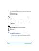
7 Release Icon Click the Release Icon to start running the job. Figure 2-14: Release Icon in the Job Manager window Note: When you release a new job, sets from the job before may be left in the Stacker / Stackers. 8 Highlight any External Profile shown in the On-line Finishers tab window and click Disable. The green check-mark in the Enabled column of the highlighted profile should now have switched to a red X as shown in the figure below.
9 Click the Profile Setup tab as shown in the figure below. Highlight any enabled profile (not the GBC FusionPunch II profile) and then click Off-line. Now highlight the GBC FusionPunch II profile and click On-line. The GBC FusionPunch II profile should now have a green check-mark in the On-line column as shown in the figure below.
10 Go back to the On-line Finishers tab and highlite the GBC FusionPunch II profile, then click Enable. The GBC FusionPunch II profile should now have a green check-mark in the Enabled column. Enable 2 Close Figure 2-17: On-line Finishers tab 11 Starting a Job Click Close to close this window. Now go back and follow steps 4 - 7.
Starting a Job Bypassing to a Downstream device To prepare for starting a printing job and sending it to the Bypass Destination, as well as the Downstream device, perform the following procedures. 1 Set up the FusionPunch II in the Bypass Destination, as well as the correct Punch mode (For FusionPunch II setup, refer to the Getting Started section, On-line / Off-line). Once the FusionPunch II is setup for the application, go to the Downstream device and enable it for On-line operation.
3 Click on the On-line Finishers tab. The window will display as shown below. On-line Finishers Tab 2 Figure 2-19: On-line Finishers tab 4 Starting a Job Verify that the profile for the Downstream device to be used is Enabled. l For punching and stacking the 11" edge in the Xerox High Capacity Stacker, ensure the HCS profile is Enabled. l For punching and stacking the 8.5" edge, ensure the GBCSE profile is Enabled.
5 Go to the Job Manager window and highlight the job to run. Click the Move Icon Move Icon. Figure 2-20: Job Manager window 6 Highlight the appropriate Queue for your job (in the figure below is an example of a SBM Queue) and then click Apply.
7 Click the Release Icon to start running the job. Release Icon Figure 2-22: Release Icon in the Job Manager window 8 Highlight any External Profile shown in the On-line Finishers tab window and click Disable. The green check-mark in the Enabled column of the highlighted profile should now have switched to a red X as shown in the figure below.
9 Click the Profile Setup tab as shown in the figure below. Highlight any enabled profile (not the SBM profile) and then click Off-line. Now highlight the SBM profile and click On-line. The SBM profile should now have a green check-mark in the On-line column as shown in the figure below.
10 Go back to the On-line Finishers tab and highlight the SBM profile, then click Enable. The SBM profile should now have a green checkmark in the Enabled column. Enable 2 Close Figure 2-25: On-line Finishers tab 11 Starting a Job Click Close to close this window. Now go back and follow steps 4 - 7.
Using the GBC Stacker The GBC Stacker is inline with the FusionPunch II and interfaces electronically and mechanically with the FusionPunch II. The Stacker will start up and shut down automatically with the Punch, under control of the Printer. The Stacker requires minimal operator intervention, with the exception of unloading the Stacker Tray.
To lower the Stacker Tray for unloading, go to the FusionPunch II Control Panel and do the following: 1 2 If in Cycle Up mode: n and only one stacker is installed, wait for the FusionPunch II and the host printer to cycle down. GBC Fusion Full Stop will be displayed in the LCD Display Screen when the machines have cycled down. n and the system is equipped with a Second Offset Stacker, you will not have to wait for the the punch and the printer to cycle down.
2-28 General Procedures
Chapter 3 Troubleshooting Clearing Jams Error Messages from the Printer from the FusionPunch II from downstream devices 3
3-2 Troubleshooting
Clearing Jams A good rule for clearing jams is to follow the paper path through the Punch and Bypass Stacker, from left to right. The jam clearing procedures are as follows: 1 Press the Stop/Reset 2 Open both Top Covers on the Punch, as shown in Figure 3-1. 3 Open (lift) the Input Ball Tracks, as shown in Figure 3-1, and clear any paper that may be jammed in that area. Also, check the printer Finisher and output tray for any paper jams. button on the Punch Control Panel.
4 Open (lift) the Input Guide Roller assembly, the Document Transport Ball Track assembly and the Sheet Eject Strap assembly, as shown in Figure 3-2 and clear any paper that may be jammed in that area. Input Guide Roller Sheet Eject Strap Document Transport Ball Track Output Guide Roller Figure 3-2: The Internal Paper Path Components 5 Remove the Output Guide Roller assembly, as shown in Figure 3-2 and clear any paper that may be jammed in that area.
Error Messages From the Printer The following is a listing of Punch-related error messages that could appear on the Host Printer display screen. Also included are a description of the possible causes and the resolution for each problem. Error Message Possible Cause DocuTech 135: 1. The current job has Clear External Finisher a fault and must be to run jobs to the reset. Bypass Transport/ External Finisher not 2. The FusionPunch II is not Online. ready. Resolution 1. Click on the Printer icon.
Error Message Possible Cause DocuTech 61XX: External Finisher Full The Punch has filled the Stacker and is waiting to be emptied. Xerox 4xxx Printer: External Finisher not ready. The FusionPunch II is not Online. Resolution Unload the Stacker and then restart the Punch Online. Press Stop/Reset at the Punch and then press "ONLINE/OFFLINE". Ensure that the Punch is in Online Mode, then press Start Xerox 4xxx Printer: External Finisher Full. The Stacker has filled and is waiting to be emptied.
Error Messages From the FusionPunch II The following is a listing of Punch-related error messages that could appear on the FusionPunch II Control Panel Display screen. Also included are a description of the possible causes and the resolution for each problem. Error Message Possible Cause Resolution Punch Covers Open The Interlock Switch under one or both of the Punch covers is not actuated. Open and close both Punch covers and ensure that they are securely closed.
Error Message Jam Entrance Sensor Possible Cause Resolution 1. Lift up the Input Track 1. There is a sheet of Ball assembly and remove paper blocking the the paper. Entrance Sensor 2. Clean the Entrance Sensor (first sensor from and reflector, using the left side of the Isopropyl alcohol and a machine). clean, lint-free cloth. If the 2. The Entrance Sensor problem persists, call your and/or its Reflector GBC or Xerox Service may be dirty. Representative. 3. The Side Guide may be adjusted too tight 3.
Error Message Jam Document Transport Sensor 1 Possible Cause Resolution 1. There is a sheet of paper blocking the first Document Transport Sensor (second sensor from the left). 2. The Document Transport Sensor 1 and/or its Reflector may be dirty. 3. The Side Guide may be adjusted too tight for the paper, cover stock, or tab stock. 1. Lift up the Document Transport Track Ball assembly and remove the paper. 2.
Error Message Jam Document Transport Sensor 2 Possible Cause Resolution 1. There is a sheet of paper blocking the second Document Transport Sensor (third sensor from the left). 2. The Document Transport Sensor 2 and/or its Reflector may be dirty. 3. The Side Guide may be adjusted too tight for the paper, cover stock, or tab stock. 1. Lift up the Document Transport Track Ball assembly and remove the paper. 2.
Error Message Jam Punch Sensor Possible Cause Resolution 1. There is a sheet of paper blocking the Punch Sensor (fourth sensor from the left). 2. The Punch Sensor and/or its Reflector may be dirty. 3. The Side Guide may be adjusted too tight for the paper, cover stock, or tab stock. 1. Lift up the Sheet Eject Strap assembly and remove the paper. 2. Clean the Punch Sensor and reflector, using Isopropyl alcohol and a clean, lint-free cloth. 3. Ensure that the Side Guide is not too tight.
Error Message Possible Cause Please Empty Stacker 1. The Stacker is full. 2. The Stacker Tray was left in the DOWN position. Resolution 1. Press the appropriate Raise/Lower Stacker button (No. 1 or No. 2) to lower the Stacker Tray. Then, unload the Stacker. 2. Press the appropriate Raise/Lower Stacker button (No. 1 or No. 2) to raise the Tray to its Home position. If the problem persists, call your GBC or Xerox Service Representative.
Error Messages From downstream devices The following is a listing of error messages that could appear on the FusionPunch II Control Panel Display screen genereted by a downstream device. Also included are a description of the possible causes and the resolution for each problem. Note: These messages will only be displayed when the FusionPunch II is set up in Bypass mode.
3-14 Troubleshooting
Chapter 4 Maintenance Cleaning the FusionPunch II 4
4-2 Maintenance
Cleaning the FusionPunch II Your FusionPunch II is designed as a high-speed, inline production Punch that requires only a minimal amount of attention from the operator. But, because it is a production machine and because it handles and punches paper, we recommend a light cleaning of the paper path components periodically, to remove accumulations of paper dust, paper chips and toner. GBC recommends the following operator maintenance practices.
What to Use GBC recommends using only 90% Isopropyl alcohol and a clean, lint-free cloth. 90% Isopropyl alcohol is available from any local pharmacy. CAUTION: To prevent possible damage to the machine, use only 90% Isopropyl alcohol. Do not use film remover or any other type of cleaning solvent. What to Clean A good rule for cleaning that is easy to remember is to follow the paper path through the Punch and Bypass Stacker, from left to right.
Cleaning the Punch 1 Open the Top Covers on the FusionPunch II, as shown in Figure 4-1. 2 Open (lift) the Input Ball Tracks, as shown in Figure 4-1. Clean the green belt under the three ball tracks, the Sensor Reflector and the Sensor (under the hole in the base plate) with Isopropyl alcohol and a clean, lint-free cloth. Check also for accumulations of paper dust or toner under the base plate.
3 Open (lift) the Input Guide Roller assembly, as shown in Figure 4-2. Clean the rollers with Isopropyl alcohol and a clean lint-free cloth. Check also for accumulations of paper dust or toner on the base plate. 4 Open (lift) the Document Transport Ball Track assembly, as shown in Figure 4-2. Clean the green belt under the ball track, both Sensor Reflectors and both Sensors (under the holes in the base plate) with Isopropyl alcohol and a clean lint-free cloth.
Side Guide Infeed Guide (Teflon® Plastic Piece) Figure 4-3: The Side Guide and Infeed Guide 6 Remove and clean the Output Guide Roller assembly and the red rollers under the Output Guide Roller assembly. Clean the rollers with Isopropyl alcohol and a clean lint-free cloth. Check also for accumulations of paper dust or toner on the base plate. 7 Close (lower) all assemblies and reinstall the Output Guide Roller assembly when finished. Close the Top Covers and resume normal operation.
Cleaning the Stacker 1 Open the Stacker Top Cover, as shown in Figure 4-4. 2 Clean the two orange O-rings on the Roller Assembly, as shown in Figure 4-4, using only 90% Isopropyl alcohol and a clean lint-free cloth. 3 Clean the large O-rings that transfer the drive to the rollers, using only 90% Isopropyl alcohol and a clean, lint-free cloth.
Cleaning the Bypass 1 Open the Stacker Top Cover. 2 Clean the three red feed rollers and the green Flat Belt, as shown in Figure 4-5, using only 90% Isopropyl alcohol and a clean lint-free cloth. 3 Clean the Sensor, as shown in Figure 4-5, using only 90% Isopropyl alcohol and a clean lint-free cloth.
4-10 Maintenance
Appendix A Personality Profiles Standard Punch Profiles Other Known Configurations A
A-2 Appendix A
61XX Personality Profiles Contents Page GBC FusionPunch II Personality Profiles: 61XX to FusionPunch II Device Profile - - - - - - - - - - - - - - - - - - A-5 61XX to FusionPunch II Device Profile - Timings - - - - - - - - - - - A-6 61XX to FusionPunch II Finisher Profile - - - - - - - - - - - - - - - - - A-7 With C.P. Bourg products downstream: 61XX to FusionPunch II to C.P.
Note: All downstream devices must be set to 6180 speed and use 6180 profiles regardless of the speed of the Host Printer. Add 2200 to the Sheet Jam time and 2600 to the Set Jam time of the downstream device’s profile, even if you have more than one GBC Bypass Stacker installed. Be sure to add any extra times specified by their profiles. Note: A-4 N.B.:(C.P.
GBC FusionPunch II Personality Profiles DocuTech 61XX to FusionPunch II Device Profile - Properties and Default Limits Tab DocuTech Models 61XX 61XX 61XX Finishers FusionPunch II FusionPunch II FusionPunch II and Xerox High Capacity Stacker Configuration Single Stacker Dual Stacker Single/Dual/High Capacity Stacker Device Name FusionPunch II FusionPunch II PunchSE Type External External External Function 1 Line Off Line Off Line Off Function 2 Line Off Line Off Line Off Sheet Se
DocuTech 61XX II DocuTech 61XX to FusionPunch II Device Profile-Properties and Default LimitsDocuTech 61XX to to FusionPunch FusionPunch II Timings Tab Device and Default LimitsDevice Profile-Properties and Default LimitsDevice Profile-Properties Profile-Properties and Default Limits) = For Each High Capacity Stacker inTimings front the FP II on a 6155 / 6180, Add 656ms To Sheet an Tab Timings Tab Set Jam Times.
DocuTech 61XX to FusionPunch II Finisher Profile - Properties and Limits DocuTech Models Finishers 61XX 61XX 61XX FusionPunch II FusionPunch II FP II and Xerox High Capacity Stacker Configuration Single Stacker Dual Stacker Single/Dual/High Capacity Stacker Profile Name GBC GBC GBCSE Type FusionPunch II FusionPunch II PunchSE Function 1 Line Off Line Off Line Off Function 2 Line Off Line Off Line Off Sheet Sequence 1-N and N-1 1-N and N-1 1-N and N-1 Side 1 Direction Face Up and
With C.P. Bourg products downstream DocuTech 61XX to FusionPunch II to C.P.
DocuTech 61XX to FusionPunch II to C.P.
DocuTech 61XX to FusionPunch II to C.P.
DocuTech 61XX to FusionPunch II to C.P.
DocuTech 61XX to FusionPunch II to C.P.
DocuTech 61XX to FusionPunch II to C.P.
DocuTech 61XX to FusionPunch II to C.P. Bourg Products Finisher Profile - Properties and Limits DocuTech Models 61XX 61XX Finishers SBM1 BBF2005 CIM / No CIM CIM / No CIM No CIM Profile Name SBM BBF2005 Type SBM1 BBF2005 Function 1 Line Off Line Off Function 2 Line Off Line Off Sheet Sequence 1-N and N-1 1-N and N-1 Side 1 Direction Face Up and Face Down Face Up and Face Down Rotate System Specified NB: Rotation needed if glue must be applied on short edge.
DocuTech 61XX to FusionPunch II to C.P.
D ocu T ech 61 X X to F u sion P u n ch II to C .P .
With the Xerox SBM2 downstream DocuTech 61XX to FusionPunch II to SBM2 – without CIM Device Profile - Properties and Default Limits Tab Personality Profiles Paper Sizes 8.5x11/8.5x14/A4 8.5x11/8.5x14/A4 8.5x11/8.
D ocuT ech 61X X to Fusion Punch II to SB M 2 – w ithout C IM D evice Profile - Properties and D efault Lim its Tab A-18 P aper S izes 8.5x11/8.
DocuTech 6155/6180 to FusionPunch II to SBM 2 –without CIM Device Profile - Properties and Default Limits – Timings Tab (*) = For Each High Capacity Stacker on a DT6155 / 6180, Add 656ms To Sheet and Set Jam Times. (#) = For Each High Capacity Stacker Add 50ms To End of Set Offset. Paper Sizes 8.5x11/8.5x14/A4 8.5x11/8.5x14/A4 8.5x11/8.
DocuTech 6155/6180 to FusionPunch II to SBM 2 –w ithout CIM Device Profile - Properties and Default Limits – Timings Tab (*) = For Each High Capacity Stacker on a DT6155 / 6180, Add 656ms To Sheet and Set Jam Times. (#) = For Each High Capacity Stacker Add 50ms To End of Set O ffset. A-20 Paper Sizes 8.5x11/8.
DocuTech 61XX to FusionPunch II to SBM2 – without CIM Finisher Profile - Properties and Limits Paper Sizes 8.5x11/8.5x14/A4 8.5x11/8.5x14/A4 8.5x11/8.
DocuTech 61XX to FusionPunch II to SBM2 – without CIM Finisher Profile - Properties and Limits A-22 Paper Sizes 8.5x11/8.
DocuTech 61XX to FusionPunch II to SBM2 – with CIM Device Profile - Properties and Default Limits Tab DocuTech Model DT 6155 / 6180 DT 6155 / 6180 Paper Sizes 8.5x11/8.
DocuTech 61XX to FusionPunch II to SBM 2 - w ith CIM Device Profile - Properties and Default Limits – Timings Tab (*) = For Each High Capacity Stacker on a DT 6155 / 6180, Add 656ms To Sheet and Set Jam Times. (*) = For Each High Capacity Stacker on a DT6100 /6115 / DT6135, Add 861m s To Sheet and Set Jam Times. (#) = For Each High Capacity Stacker Add 50ms To End of Set O ffset. A-24 DocuTech M odel DT 6155 / 6180 Paper Sizes 8.5x11/8.
DocuTech 61XX to FusionPunch II to SBM 2 – w ith CIM Finisher Profile - Properties and Limits DocuTech M odel DT 6155 / 6180 Paper Sizes 8.5x11/8.
DocuTech 135 Host Machine Enablement 1. Open the Job manager. 2. Log in with your user ID and password. 3. Go to the top right corner of the keyboard and press Diagnostics. NOTE: If you have a job in the printer queue, the DocuTech will prompt you to switch immediately. 4. Press yes. 5. After Diagnostics have been invoked, select DC Controller, found in the top left corner of the screen. 6. Go to Controller DC 105 and enable BYPASS TRANSPORT by selecting “other”. 7.
Xerox 4xxx LPS Host Machine Enablement 1. Stop any job that is currently running and take the system offline. 2. Log in at the log4 level. Type log 4 and press Enter. 3. Type Field Engineer and press Enter. 4. Type edit and press Enter. The prompt, EDIT> displays. 5. Type INS 10,10 and press Enter. A line number will display, for example, 000010. 6. Type CLEAR = OUT135,0,0,0,0,0,0,0,0,0,0,0; and press Enter. The next line number will display, for example, 000020. 7.
Xerox 4xxx NPS Host Machine Enablement The procedure that follows describes how to configure a GBC profile for Xerox 4000 Family NPS printing systems. This profile allows you to send a job through a network and then change the output destination at the Sun NPS Workstation. Once you have set up the GBC profile, you will be required to configure a GBC Print Queue.
Xerox 4xxx Output Profile 1. Type Set Output Profile and press Enter. The system will prompt you for the name of the profile. 2. Type the name of the profile exactly as it was originally entered and press Enter. The system will display a message indicating that the profile is set. Configuring a GBC Print Queue 1. Type Priv admin (space) and press Enter. The system will prompt you for a password. 2. Type administrator as your password. The prompt, Ps Admin displays.
A-30 Appendix A
Glossary Glossary of Common FusionPunch II Terms G
G-2 Glossary
Glossary of Common FusionPunch II Terms The following is a glossary/definition of terms that are common to the GBC FusionPunch II and all related inline finishing devices. Backgauge - an adjustable assembly that serves as a stop for the paper when it arrives under the Punch Die. The adjustment of the Backgauge determines the distance from the long edge of the paper to the punched holes. This adjustment applies only when a GBC Cerlox 19-hole Punch Die set is in use.
Die Pins - the actual cutting tools that are part of the Die Set. Each Die Pin cuts a hole in the paper. A die set that punches several holes has several die pins. Also, these pins are individually removable to adjust for different widths of paper, or for replacement, in case one becomes damaged. Document Transport Ball Track Assembly - an assembly that is located in the center of the paper path through the Punch.
Inline - same as "in series with", or directly behind another device. The FusionPunch II is inline with the printer and the Stacker, in turn, is inline with the FusionPunch II. Misfeed - a condition that occurs when paper becomes folded or wrinkled and becomes stuck while feeding, thereby causing a paper jam. Offline - when finishing devices are not being fed or controlled by the printer in a live production run. When the FusionPunch II and Stacker are being fed manually, they are in offline mode.
Printer - the machine that actually produces the documentation (prints the books) and controls the finishing devices. The Xerox DocuPrint and DocuTech are examples of printers. Print Queue - a set of values or system configuration parameters in the printer’s operating system that communicates input and output information from the printer to a finishing device, such as the FusionPunch II. The System Administrator can set up or change these values from the keyboard.
Right Punch Door - the narrow door in the front of the Punch cabinet that, when opened, allows access to various adjustment knobs and to the Slug (punched paper chaff) Bin, which must be emptied periodically. Setting the Backgauge - an adjustment procedure that is done to ensure that the margin between the leading edge of the paper and the punched holes is correct.
Stacker Tray - a tray internal to the Stacker, as described above. System Administrator - the person who is responsible for setting up and maintaining the printer’s operating system. The System Administrator also installs new software, when necessary. Two-Sided - a printing job that uses both sides of the paper; also called Double-Sided, or Duplex.