User’s Guide XELTEK Superpro®7000 Series Ultra‐Fast, Stand‐Alone, 144pin Programmer of the Future XELTEK 1296 Kifer Rd. Unit 605 Sunnyvale, CA 94086 Tel: (408) 530‐8080 Fax: (408) 530‐0096 www.xeltek.
IMPORTANT! 1. This manual applies to SuperPro/7000. 2. Make sure the software installation is completed before connecting the programmer to PC. 3. Please read the manual carefully before using programmers. 4. Please use Xeltek Adapters. Non‐Xeltek adapters will cause error XELTEK 1296 Kifer Rd. Unit 605 Sunnyvale, CA 94086 Tel: (408) 530‐8080 Fax: (408) 530‐0096 www.xeltek.com SUPERPRO is the registered trademark of XELTEK.
Distribution and sales of this product are intended for use by the original purchaser under the terms of the License Agreement. This document may not, in whole or part, be copied, photocopied, reproduced, translated or reduced to any electronic medium of machine‐readable form without prior consent in writing from XELTEK. The information in this document is subject to change without notice.
Table of Contents Welcome .................................................................................................................................. 1 Feature Highlights .............................................................................................................. 1 User Manual Organization ................................................................................................. 2 Chapter 1 Overview of SUPERPRO® 7000...........................................................
4.2 Project Menu............................................................................................................... 26 4.2.1 Load Project.. ……............................................................................................ 26 4.2.2 Save Project Files.............................................................................................. 27 4.2.3 Manage Project Library.................................................................................... 27 4.2.
License Agreement.......................................................................................................... 50 Warranty..........................................................................................................................
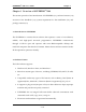
SUPERPRO® 7000 User’s Guide Welcome Welcome Welcome to the world of Xeltek SUPERPRO programmers. Xeltek has produced the SUPERPRO line of IC programmers since 1985. Our motto is to provide high value products at affordable prices. In the past 27 years, Xeltek has produced a string of highly popular and successful programmers including SUPERPRO, SUPERPRO II, SUPERPRO III, SUPERPRO V, SUPERPRO 680, SUPERPRO 8000, SUPERPRO 3000U, and SUPERPRO 9000 models.
SUPERPRO® 7000 User’s Guide Welcome A 144 pin driver support is built-in to provide efficient programming of large pin count devices, an additional pin expander module is not necessary to program large pin-count devices. The SUPERPRO operates with a PC for engineering purpose or in standalone mode, without a PC, for repeat production mode programming. This provides seamless migration from engineering to production. The SUPERPRO communicates through a USB 2.
SUPERPRO® 7000 User’s Guide Welcome An introduction to the SUPERPRO series, including the system requirements and the software and hardware installation Detailed explanations on the commands and the programming procedures Information about error messages and common problems An Appendix that includes the customer support information Note: The software prevails in any discrepancy between it and the user manual, due to any upgrades of the software.
SUPERPRO® 7000 User’s Guide Chapter 1 Chapter 1 Overview of SUPERPRO® 7000 This section provides a brief introduction of SUPERPRO (1.1), software features (1.2), structure of the handbook (1.3), system requirement for the installation (1.4), and package content (1.5). 1.1 Introduction to SUPERPRO The SUPERPRO is a menu-driven software that operates a series of cost-effective, reliable, and high-speed universal programmers. SUPERPRO communicates through a USB 2.
SUPERPRO® 7000 User’s Guide Chapter 1 1.3 Structure of this User’s Guide The content of this User’s Guide is structured into three major sections, Chapter 1 is an overview and introduction of the SUPERPRO, describing the system requirement, installation of the hardware and software. Chapter 2 – Chapter 5 are detailed specification and explanation of all the features, commands, and function modules. In Appendices, there are supportive information and guide for trouble-shooting 1.
SUPERPRO® 7000 User’s Guide A CD contains driver software A user’s registration form Chapter 1 6 of 51
SUPERPRO® 7000 User’s Guide Chapter 2 Chapter 2 System Installation This chapter provides a brief guidance on how to install the SUPERPRO software and connect the programmer hardware properly. NOTE: To avoid complications during the installation process, you must setup the software before connecting the programming hardware (the USB device) to your computer.
SUPERPRO® 7000 User’s Guide Chapter 2 3. Select the appropriate programmer model. 4. Click Setup. NOTE: Each model has its own software and they are NOT compatible. 2.1.2 Download the software from website and setup (recommended) You can also download the specific software for a certain model at Xeltek website: http://www.xeltek.com. Select the icon to download the appropriate file for your programmer. Once you have saved the file to your computer, run it to setup the software.
SUPERPRO® 7000 User’s Guide Chapter 2 2. An installation wizard will be displayed (as illustrated below). Click Next to continue. 3. A License Agreement will be displayed. Click I Agree to continue.
SUPERPRO® 7000 User’s Guide Chapter 2 4. Choose the Destination Location in which the driver software will be installed. Once the destination file folder is selected, click Next to proceed. 5. Another dialog box will be presented and allow the user to choose whether creating a start menu icon and/or a desktop icon. Once correctly check the tick box(es), click Next to continue.
SUPERPRO® 7000 User’s Guide Chapter 2 6. Check the previous selections and click Install to start the installation. NOTE: If you are using the Windows Vista system, the operation system may display the following dialog box to ask you whether to install the software. Select Install this driver software anyway.
SUPERPRO® 7000 User’s Guide Chapter 2 7. Once the installation is completed, click Finish. 2.2 Hardware and Driver Installation After you set up the software, you can install the hardware and driver. The following procedure explains the installation process. NOTE: Do not follow these steps below if you have not yet setup the software (see section 2.1). 1. Make sure all other programs are closed during the installation process. 2. Connect the programmer module to the computer through the USB port. 3.
SUPERPRO® 7000 User’s Guide Chapter 2 4. After you open the application software for the programmer, the system automatically starts the initialization. If it does not, make sure the programmer is securely connected to the computer and that the power switch is on.
SUPERPRO® 7000 User’s Guide Chapter 3 Chapter 3 Quick Guidance of the Software Features This chapter is a quick guidance of the SUPERPRO® software. It describes the functions and features of the programmer that are most frequently used. The SUPERPRO 7000 provides two programmers in one, they are: PC mode for engineering and Stand-alone mode for production. Under PC hosted mode, a PC controls the programmer via a high-speed USB connection to program a chip.
SUPERPRO® 7000 User’s Guide Chapter 3 1. The Menu Bar provides access to the File, Buffer, Device, Option, Project, and Help menus. 2. The Tool Bar offers quick access to many commonly used functions. 3. The Command Window enables shortcut to many commands and operations. 4. The Programmer Statue Panel shows the state of the current project and programmer. 5. The Device Panel shows the connected device. 6. The Buffer Panel shows the state of the buffer. 7.
SUPERPRO® 7000 User’s Guide Chapter 3 3.2 Programming Procedures This section provides information on steps for common procedures to programme devices using SUPERPRO 7000. Before using the programmer to program a device, make sure that the programmer is installed properly and that the computer and programmer are communicating successfully. Make sure that you have the appropriate adapter for your SMD devices, if applicable. Insert the chip correctly.
SUPERPRO® 7000 User’s Guide 3.2.2 Chapter 3 Load data into buffer One can load data into the buffer by reading data either from a file or a master chip. To read data from a file, select Load File from the File menu. The system displays the Load File dialog box. To make sure the loaded data is correct one can review the information in the Buffer window. NOTE: Some Hex or S record files contain non‐zero file initial address. In this case, enter the start address in the File Address box.
SUPERPRO® 7000 User’s Guide Chapter 3 o Address Change indicates whether a different start and end address shall be applied for the programming zone of the device. To set the order of the batch processing functions, select Edit Auto from the Options menu. The system displays the Edit Auto screen. For devices that include the configuration word, you must set the configuration word before programming to ensure that the chip can be used on the target system.
SUPERPRO® 7000 User’s Guide Chapter 3 Verify NOTE: This step is necessary. The chip must pass Verification before the programming can be implemented. Some chips provide only the accumulation check function, such as VerifyCRC instead of a unit‐to‐unit check function. Very few chips do not provide the accumulation check function. Security or Protect if encryption is required NOTE: You may need to set the configuration word before performing encryption.
SUPERPRO® 7000 User’s Guide Chapter 3 1. Enter the new password in the Enter the password field. Leave the field blank to indicate no password is required. 2. Re-enter the password. Both fields must match for a valid password. NOTE: Spaces are characters that can be used in the password. The system asks for a password whenever performing a function that requires a password. The Enter Password screen is illustrated below. 3.
SUPERPRO® 7000 User’s Guide Chapter 3 In normal mode, all operations (i.e. selecting devices, loading documents and programming) are carried out in the programmer that is selected and highlighted at the time being. In global configuration mode, all the operations are carried out in the programmer(s) that is selected with the check in tick-box(es). NOTE: Choose specified hub for XELTEK to connect SUPERPRO/7000, and currently up to 8 programmer can be operated simultaneously.
SUPERPRO® 7000 User’s Guide Chapter 4 Chapter 4 Functions and Commands This chapter provides a detailed specification and explanation of the SUPERPRO® software. It includes the description of the functions and commands that is listed as below, File Menu and Tool Bar (4.1) Project Menu (4.2) Device Menu (4.3) Option Menu (4.4) Tool Bar (4.5) Log History Window (4.6) 4.1 File Menu and Tool Bar The File menu provides access to the commands of Load, Save, Recent Projects, and Exit.
SUPERPRO® 7000 User’s Guide Chapter 4 apply: With a HEX/ASCII data buffer (EPROM, MCU etc.), the system assumes that 8 bits of the data are valid. With a JEDEC buffer (PLD/PAL), the system considers the lowest bit (1 bit) of the file data valid. Select Load from the File menu to open the Load File dialog box, as illustrated below. The red labels refer to the numbered notations follow this figure. 1. Buffer. To select the Buffer name from the drop down list.
SUPERPRO® 7000 User’s Guide Chapter 4 3. File Type. To select the type of the file from a drop down list. Different file types are included here, e.g. Binary, Intel Hex, Motorola S record, JEDEC, POF, TI, etc. 4. File Mode.
SUPERPRO® 7000 User’s Guide Chapter 4 7. Buffer clear on data load. Tick this checkbox will enable the user to fill the data buffers with the specified data. NOTE: Ticking the checkbox of Custom File will disable most loading option. 4.1.2 Save File Select Save from the File menu to save data in the current buffer to a disk file. A dialog box titled as Save File will be displayed and the saving options are similar to those in section 4.1.1 Load File. 1. Buffer. 2.
SUPERPRO® 7000 User’s Guide Chapter 4 3. File Type 4. Buffer Address 5. Data Size. To enter the save data size in number of bytes. 4.2 Project Menu The project file contains all of the information and preparations before programming. It can also be used to restore the working environment that has been saved previously.
SUPERPRO® 7000 User’s Guide Chapter 4 4.2.2 Save Project Files Select Save Project Files from the Project menu to save the current working environment to a specified project file. To ensure the security of the data, you can encrypt the project file. NOTE: The project file name can be made of max 15 characters, and only be saved using the .prj extension. 4.2.
SUPERPRO® 7000 User’s Guide Chapter 4 The figure below shows a typical Manage Project Library window. Some basic commands related to the project file operation are: Send Project. This will send the existing project file(s) to the SD card. One can also encrypt the SD card to protect the data. Delete Project. To delete the project being selected. There are many SD card manufacturers in the market and the quality varies a lot across different brands.
SUPERPRO® 7000 User’s Guide Chapter 4 Unlock. To enter the correct password enable operation on the SD card when it is connected on-line. However, if the SD card is off-line/disconnected, the user has to unlock it again for any other operation. Erase Password. This operation actually wipes all the information that is stored in the SD card and removes the password. After this, the SD card needs to be format using FAT32 file system, so as to be compatible to SUPERPRO® 7000.
SUPERPRO® 7000 User’s Guide Chapter 4 4.3.3 Manage data in buffer There are two major types of buffer, Fuse Buffer and Data Buffer (HEX/ASCII buffer). In following section the operations of these two types of buffer is described and a typical buffer operation window is shown below. 4.3.3.1 HEX/ASCII Data Buffer Locate. Enter the address of the data you wish to display and select OK to quickly move the cursor to the desired location. Fill.
SUPERPRO® 7000 User’s Guide Chapter 4 Radix. Select Radix to toggle between the HEX and DEC memory address display. Search. Select Search to search for a specified string. Select Search Next to begin the next search for the specified string Swap. Select Swap to open the Word Swap dialog box, illustrated below. Select the Word Width option to swap high byte and low byte according to the specified width in the address range and select OK. Otherwise, select Cancel.
SUPERPRO® 7000 User’s Guide Chapter 4 4.3.3.2 Fuse Buffer When you select Edit from the Buffer menu with the appropriate file type, the system opens the Fuse Buffer Edit window, illustrated below. The data for editing is either 0 or 1. Refer to the data manual of the device and the JEDEC to determine which of the following explanations for the data apply. 1 represents an intact fuse and 0 represents a blown fuse, or 1 represents a blown fuse and 0 represents an intact fuse 4.3.
SUPERPRO® 7000 User’s Guide Chapter 4 Some single-chip microcomputers allow special working modes, such as the storage area mapping, the watchdog time, the clock, or the encryption. Set these special modes through the Device Configuration Word option. The user files contain the configuration words of some devices. When you load these files, the system automatically loads the configuration words into the configuration word buffer. However, you must select the configuration words for some devices manually.
SUPERPRO® 7000 User’s Guide Chapter 4 pages before programming a chip.
SUPERPRO® 7000 User’s Guide Buffer Auto.Inc Count Chapter 4 Each view is explained in the following sections 4.4.1 General 1. For chips with 48 pins or less or for chips with an adaptor that reduces the chip to 48 pins or less, select Insertion Test to have the programmer check the pin contact status before programming. The test includes a check for poor contact, wrong direction, chip insertion, and chip insertion orientation errors. 2.
SUPERPRO® 7000 User’s Guide Chapter 4 3. Select Beeper On to turn the beeper on or off. The beeper makes a sound to indicate the results of operations such as Insertion Test error, ID unmatched, programming successfully completed or failed. NOTE: Not all programmers include a beeper. 4. Indicate the mode for verifying the data by selecting one of the Verify Mode options. These options refer to the voltage of the pin VCC, which may vary when the programmer verifies the data.
SUPERPRO® 7000 User’s Guide Chapter 4 The default programming method is to program the device from the start address to the end address. However, you may choose to program only a part of the chip, such as with most E/EPROM (FLASH) devices. 4.4.3 Auto Increment (Auto.Inc) Auto Increment provides two methods of generating the serial numbers: Auto Increment and User Defined. This function is not available in stand-alone mode.
SUPERPRO® 7000 User’s Guide Chapter 4 NOTE: The serial number is the content required by some applications that must be written in a certain area for every chip. This information includes the product sequence number and the MAC address. To have the software generate the serial number, select Enable AutoIncrement. 1. Enter the automatic start buffer address in the Start Addr field. 2. Enter the automatic end buffer address in the End Addr field. 3. Enter an increment value less than 10 in the Inc.
SUPERPRO® 7000 User’s Guide Chapter 4 The Auto function organizes the different functions of the device into a sequential group and carries out the functions in order, similar to a batch command. Edit Auto enables edit functions and operations, in order to automatically execute the programming procedure according to pre-arranged functions and operations.
SUPERPRO® 7000 User’s Guide Chapter 4 can be seen from the figure above, user can select one certain function/operation and Add, Delete the selected one, or Delete All to cancel all the previous arrangement. 4.5 Tool Bar The tool bar provides a quick way to execute common functions. The toolbar from the main SUPERPRO screen is illustrated below. Each tool is labeled with a number and described below. 1. Load file 2. Save file 3. Load project 4. Save project 5. Edit buffer 6. Calculating the Checksum 7.
SUPERPRO® 7000 User’s Guide Chapter 4 4.6 Log History Window User can create a log file to have the system save Operation Information window content into a log file when you exit the program. Select Log File from the Option menu to open the Log File dialog box, illustrated below. The red labels refer to the numbered explanations below 1. Select No to delete the log file. The system will not create a log file on exit. 2. Select New to overwrite the existing log file every time the program starts. 3.
SUPERPRO® 7000 User’s Guide Chapter 5 Chapter 5 Frequently Asked Questions (FAQ) You can monitor the programmer operations through the Operation Information Window and message window. This chapter helps define common problems related to programmer actions and errors. 5.1 Dealing with Data Files This section explains common problems involving the File Type dialog box. 5.1.1 Solve Invalid File Type or File Data Overflow Error The data for programming is usually stored in the data file.
SUPERPRO® 7000 User’s Guide Chapter 5 several times according to your needs. There are three methods for separating the file data: Based on byte (8bit), divide the file into two parts by the odd and even address. Program the two parts into two chips respectively. When loading the file, select Even as the File Mode to write the data in the addresses 0,2,4,6, etc. to one chip. Select Odd as the File mode to write the data at the address 1,3,5,7, etc. to the other chip.
SUPERPRO® 7000 User’s Guide Chapter 5 Write the data from the address 4000 (Hex) of the file Sample3 to the address 4000 (Hex) of the chip. 1. Select Edit from the Buffer menu. Make sure that the Buffer clear on data load option is not checked. 2. Select Load from the File menu to load the Sample1 file. o In the Buffer Address field, enter 0. o In the File Address field, enter 200. 3. Select Load from the File menu to load the Sample2 file. o In the Buffer Address field, enter 3000. o In the 4.
SUPERPRO® 7000 User’s Guide Chapter 5 o Unmatched file to this chip: This POF file does not match this chip. The POF file is related to the device when it is compiled. The error indicates that this POF file is not for this device. Replace the chip with a matched one. o The POF file has errors. o Load POF file dll error (not found): An auxiliary file has errors. Contact technical support for assistance. 2. Files of other formats are mainly the JED files.
SUPERPRO® 7000 User’s Guide Chapter 5 5.3 Other Messages Other error messages are explained below. Please edit ‘Auto’ first: The Auto consequence is blank. Edit Auto and try again. Enter a string to search for: The Hex Edit Search dialog box is blank. Make sure to enter a specified string or ASCII codes to search for in the Buffer Edit dialog box. The string for search is blank. Input it in Search dialog: Enter a string in the Buffer Edit dialog box.
SUPERPRO® 7000 User’s Guide Chapter 5 Programmer not ready: Turn off the programmer power switch and turn it on again after a few seconds. Programmer is running: The programmer hardware is operating. Wait until the operation is finished. File open error: The open file operation failed. Out of Memory: The memory overflows.
SUPERPRO® 7000 User’s Guide Appendix Appendix XELTEK periodically publishes upgrade software on the XELTEK website. You can download and upgrade your software from the website. Non‐users may download the software for evaluation. Troubleshooting If the User Manual does not answer your questions, first contact your sales agent or the distributor. If you still need technical assistance you can call XELTEK between Mon‐Fri 7:30AM‐12:00PM & 1:00PM ‐ 4:30PM (PST).
SUPERPRO® 7000 User’s Guide Appendix Contact Information XeltekInc. 1296 Kifer Rd. Suite # 605 Sunnyvale, CA 94086 United States General Consultation 001‐408‐530‐8080 Order/Sales 001‐408‐530‐8080 Email: sales@xeltek.com Technical Support 001‐408‐530‐8080 Email: techsupport@xeltek.com Fax: 001‐408‐530‐0096 Website: http://www.xeltek.
SUPERPRO® 7000 User’s Guide Appendix License Agreement The copyright of the program and the Userʹs Guide remain the property of XELTEK. You may: 1. Copy the program for back‐up purposes ONLY in support of its use on a single computer. 2. Transfer the program and license to another party if the other party agrees to accept the terms and conditions of this agreement. You may not: 1.
SUPERPRO® 7000 User’s Guide Appendix Warranty XELTEK has a strict quality assurance system. If the software or hardware has any defects, it can be repaired or replaced free according to the specific situation within one-year period after the user buys the product. The warranty is based on proper installation of the software and usage in the specified working environment.