
RV Series Remote Control Owner's Manual RC/GS RC7

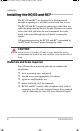
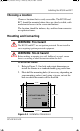
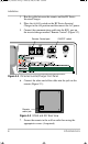
Table Of Contents
- Important Safety Instructions
- Introduction
- Installation
- Configuration
- Set Idle
- Battery Capacity
- Battery Type
- Max Charge Rate
- Set Shore Power
- Remote Setup
- LCD Contrast
- Set Clock (RC/GS Only)
- Select Genset (RC/GS Only)
- Generator Start (RC/GS Only)
- Generator Stop (RC/GS Only)
- Thermostat Start Enable and Disable (RC/GS Only)
- Begin Gen Quiet and End Gen Quiet (RC/GS Only)
- Saving Setup Choices
- RV Series Inverter/Charger and RC/GS and RC7 Setup
- Auto Gen Start Setup (RC/GS Only)
- Operation
- Status LEDs
- LCD Screen
- Buttons
- AC Source Messages
- Genset Error Messages (RC/GS Only)
- Inverter Mode Messages
- Charger Mode Messages
- Inverter/Charger Error Messages
- Meters Display
- System Status Messages
- Preparation for Storage
- System Status Messages
- Generator Status Messages (RC/GS Only)
- System Status Display
- Meters Display
Installing the RC/GS and RC7
975-0210-01-01 7
Choosing a location
Choose a location that is easily accessible. The RC/GS and
RC7 should be mounted where they are clearly visible, with
unobstructed access to the screen and buttons.
The location should be indoors, dry, and free from corrosive
or explosive fumes.
Mounting and Connecting
To install the remote:
1. Refer to Figure 2-1 for hole and cutout dimensions or
install the remote in a standard double-gang outlet box.
2. Pilot-drill the mounting holes (if necessary, depending on
your mounting surface) and, using a jigsaw, cut out the
hole in which the remote will be inserted.
WARNING: Fire hazard
The RC/GS and RC7 are not ignition protected. Do not install in
areas requiring ignition-protected equipment.
WARNING: Shock hazard
Before making an opening in a wall, bulkhead, or panel, ensure
there is no wiring or other obstruction within the wall.
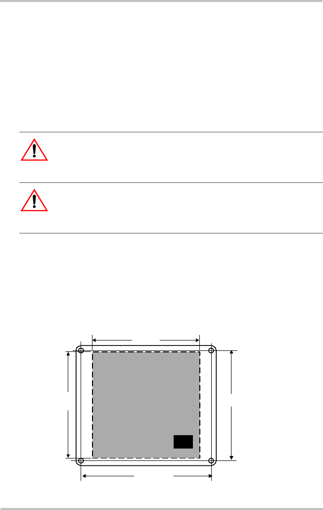
Figure 2-1
Installation Dimensions
CUT OUT THIS AREA
PHON E
JACK
4-1/8"
4"
5-3/16" c-c
4-1/4" c-c
FRONT VIEW
RC-GS_manual.book Page 7 Thursday, May 26, 2005 4:58 PM