
- Xantrex Solar Inverter Owner's Manual


975-0253-01-01 xi
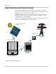
Figure 1-1 Basic System Overview - - - - - - - - - - - - - - - - - - - - - - - - - - - - - - - - - - - - - - - - - - - - 1–2
Figure 1-2 Main Features of the GT Inverter- - - - - - - - - - - - - - - - - - - - - - - - - - - - - - - - - - - - - - 1–3
Figure 2-1 Installation Options Overview - - - - - - - - - - - - - - - - - - - - - - - - - - - - - - - - - - - - - - - - 2–3
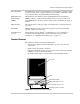
Figure 2-2 GT Inverter mounting orientation - - - - - - - - - - - - - - - - - - - - - - - - - - - - - - - - - - - - - 2–5
Figure 2-3 Installation Overview- - - - - - - - - - - - - - - - - - - - - - - - - - - - - - - - - - - - - - - - - - - - - 2–10
Figure 2-4 GT Inverter Dimensions- - - - - - - - - - - - - - - - - - - - - - - - - - - - - - - - - - - - - - - - - - - 2–11
Figure 2-5 Mounting Bracket and GT Inverter - - - - - - - - - - - - - - - - - - - - - - - - - - - - - - - - - - - 2–12
Figure 2-6 Examples of Mounting on a Pole or Rails - - - - - - - - - - - - - - - - - - - - - - - - - - - - - - - 2–14
Figure 2-7 Installing the Mounting Bracket using Plywood Support - - - - - - - - - - - - - - - - - - - - - 2–15
Figure 2-8 Proper Placement of the Inverter on the Mounting Bracket - - - - - - - - - - - - - - - - - - - 2–16
Figure 3-1 PV Quick Connect Location - - - - - - - - - - - - - - - - - - - - - - - - - - - - - - - - - - - - - - - - - 3–2
Figure 3-2 DC Connections for a Two-String PV Array - - - - - - - - - - - - - - - - - - - - - - - - - - - - - - 3–4
Figure 3-3 AC Connector (female) - - - - - - - - - - - - - - - - - - - - - - - - - - - - - - - - - - - - - - - - - - - - 3–6
Figure 3-4 AC Connector Terminals - - - - - - - - - - - - - - - - - - - - - - - - - - - - - - - - - - - - - - - - - - - 3–6
Figure 3-5 Improper multiple inverter connections- - - - - - - - - - - - - - - - - - - - - - - - - - - - - - - - - - 3–7
Figure 3-6 Daisy Chain Layout- - - - - - - - - - - - - - - - - - - - - - - - - - - - - - - - - - - - - - - - - - - - - - - 3–8
Figure 3-7 Male Network Terminator - - - - - - - - - - - - - - - - - - - - - - - - - - - - - - - - - - - - - - - - - - 3–9
Figure 3-8 Location of Xanbus RJ45 Ports - - - - - - - - - - - - - - - - - - - - - - - - - - - - - - - - - - - - - - - 3–9
Figure 3-9 RJ45 Connector - - - - - - - - - - - - - - - - - - - - - - - - - - - - - - - - - - - - - - - - - - - - - - - - 3–10
Figure 3-10 Replacing the Comm Port Cover - - - - - - - - - - - - - - - - - - - - - - - - - - - - - - - - - - - - - 3–12
Figure 3-11 GT-View Display - - - - - - - - - - - - - - - - - - - - - - - - - - - - - - - - - - - - - - - - - - - - - - - 3–13
Figure 3-12 GT-View Options - - - - - - - - - - - - - - - - - - - - - - - - - - - - - - - - - - - - - - - - - - - - - - - 3–14
Figure 5-1 Front Panel LCD Location - - - - - - - - - - - - - - - - - - - - - - - - - - - - - - - - - - - - - - - - - - 5–2
Figure 5-2 Location of Status Indicator Lights - - - - - - - - - - - - - - - - - - - - - - - - - - - - - - - - - - - 5–10
Figure A-1 Output Power vs. Ambient Temperature - - - - - - - - - - - - - - - - - - - - - - - - - - - - - - - - -A–4
Figure A-2 Typical Efficiency- - - - - - - - - - - - - - - - - - - - - - - - - - - - - - - - - - - - - - - - - - - - - - - -A–5
Figures