GT 2.5-DE GT 3.8-DE GT 2.8-SP GT 3.
Xantrex Grid Tie Solar Inverter Owner’s Manual
About Xantrex Xantrex Technology Inc. is a world-leading supplier of advanced power electronics and controls with products from 50 watt mobile units to one MW utility-scale systems for wind, solar, batteries, fuel cells, microturbines, and backup power applications in both grid-connected and stand-alone systems. Xantrex products include inverters, battery chargers, programmable power supplies, and variable speed drives that convert, supply, control, clean, and distribute electrical power.
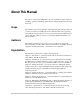
About This Manual The purpose of this Owner’s Manual is to provide explanations and procedures for installing, operating, maintaining, and troubleshooting the Xantrex Grid Tie Solar Inverter™. Scope The manual provides safety guidelines, detailed planning and setup information. It provides procedures for installing the inverter and information about operating and troubleshooting the unit. It does not provide details about particular brands of photovoltaic (PV) panels.
About This Manual Conventions Used The following conventions are used in this guide. WARNING Warnings identify conditions that could result in personal injury or loss of life. CAUTION Cautions identify conditions or practices that could result in damage to the unit or other equipment. Important: These notes describe things that are important for you to know, but not as serious as a caution or warning.
About This Manual Symbols Used Alternating Current (AC) Direct Current (DC) In this guide: Important information, warnings, or cautions. On the product: Important information, warnings or cautions with further explanation in the product guide. Caution, risk of electric shock. FOR AUTHORIZED SERVICE PERSONNEL: Before opening cover, disconnect DC and AC power and wait 30 minutes to allow internal voltages to reach safe levels. NOTE: there are no user-serviceable parts inside.
vi
Important Safety Instructions SAVE THESE INSTRUCTIONS—This manual contains important instructions that shall be followed during the installation and maintenance of the Xantrex Grid Tie Solar Inverter. 1. Before installing and using the GT Inverter, read all instructions and cautionary markings on the inverter and in all appropriate sections of this guide. 2. To reduce risk of fire hazard, do not cover or obstruct the heat sink. 3. Observe the clearance recommendations as described on page 2–12.
Safety Regulatory Compliance The GT Inverter is CE Marked for the following Directives and standards: • • Low Voltage Directive 73/23/EEC, per EN50178 “Electronic Equipment for Use in Power Installations”.
Contents Important Safety Instructions - - - - - - - - - - - - - - - - - - - - - - - - - - - - - - - - - - - - - - - - - - - vii Regulatory Compliance viii 1 Introduction About the Xantrex Grid Tie Solar Inverter - - - - - - - - - - - - - - - - - - - - - - - - - - - - - - - - - - - - - - 1–2 Standard Features - - - - - - - - - - - - - - - - - - - - - - - - - - - - - - - - - - - - - - - - - - - - - - - - - - - - 1–3 2 Installation Installation Options - - - - - - - - - - - - - - - - - - - - - - - - - - - -
Contents Connecting Network Cable between Inverters - - - - - - - - - - - - - - - - - - - - - - - - - - - - - - - -3–12 Communications Wiring for Monitoring a Single Inverter - - - - - - - - - - - - - - - - - - - - - - - -3–12 4 Starting the Inverter Commissioning Procedure - - - - - - - - - - - - - - - - - - - - - - - - - - - - - - - - - - - - - - - - - - - - - - - - 4–2 Disconnect Test - - - - - - - - - - - - - - - - - - - - - - - - - - - - - - - - - - - - - - - - - - - - - - - - - - - - - - - 4–3 5
Figures Figure 1-1 Figure 1-2 Figure 2-1 Figure 2-2 Figure 2-3 Figure 2-4 Figure 2-5 Figure 2-6 Figure 2-7 Figure 2-8 Figure 3-1 Figure 3-2 Figure 3-3 Figure 3-4 Figure 3-5 Figure 3-6 Figure 3-7 Figure 3-8 Figure 3-9 Figure 3-10 Figure 3-11 Figure 3-12 Figure 5-1 Figure 5-2 Figure A-1 Figure A-2 Basic System Overview - - - - - - - - - - - - - - - - - - - - - - - - - - - - - - - - - - - - - - - - - - - - 1–2 Main Features of the GT Inverter- - - - - - - - - - - - - - - - - - - - - - - - - - - - - - - - - -
xii
Tables Table 2-1 Table 2-2 Table 3-1 Table 3-2 Table 5-1 Table 5-2 Table 5-3 Table 5-4 Table 5-5 Table 5-6 Table 5-7 Table 5-8 Table 5-9 Table 5-10 Table 5-11 Table 6-1 MPPT Operational Window - - - - - - - - - - - - - - - - - - - - - - - - - - - - - - - - - - - - - - - - - 2–6 Inverter Clearance Requirements - - - - - - - - - - - - - - - - - - - - - - - - - - - - - - - - - - - - - 2–12 T568A Standard Wiring - - - - - - - - - - - - - - - - - - - - - - - - - - - - - - - - - - - - - - - - - - - 3–10 Network
xiv
1 Introduction Chapter 1, “Introduction”, contains information about the features and functions of the Xantrex Grid Tie Solar Inverter.
Introduction About the Xantrex Grid Tie Solar Inverter The Xantrex Grid Tie Solar Inverter (GT Inverter) is designed to convert solar electric (photovoltaic or PV) power into utility-grade electricity that can be used by the home or sold to the local power company. Installing the GT Inverter consists of mounting it to the wall and connecting the DC input to a PV array and the AC output to the utility. See Figure 1-1 for a simple diagram of a typical installation.
About the Xantrex Grid Tie Solar Inverter PV compatibility The GT Inverter is designed to take advantage of solar modules configured as high voltage PV string arrays—single crystalline, poly crystalline, or thin film—with a 195 to 550 Vdc input voltage Maximum Power Point range. Maximum Power Point Tracking (MPPT) The GT Inverter uses Xantrex proprietary Maximum Power Point Tracking (MPPT) technology to harvest the maximum amount of energy from the solar array.
1–4
2 Installation Chapter 2, “Installation”, provides information about planning for and installing the GT Inverter. It contains information to help you plan wire routes, ensure your PV array provides necessary power, and find a suitable location for installation. The topics in this chapter are organized as follows: • “Installation Options” on page 2–2 • “Planning the Installation” on page 2–2 • “Preparing for the Installation” on page 2–9 • “Mounting the Inverter” on page 2–10.
Installation Installation Options The GT Inverter may be installed as a single inverter for a single PV array of one or two PV strings, or in a multiple inverter configuration for multiple PV arrays (see Figure 2-1 for diagrams of both options). Single Inverter Installation In this configuration, a single inverter collects the harvested solar energy and routes the power to the main utility service panel and the utility grid.
Planning the Installation Utility Grid Single Inverter Installation Xantrex GTInverter Main Utility Service DC converted Panel to AC Photovoltaic Panels - PVArray SurplusUtility power routed to UtilityMeter Grid Utility Grid Utility PV String #1 Surpluspower routed to MeterUtilityGrid Harvested solar energy Loads Harvested solar energy DCconverted to AC PVString #2 Gr id Tie S olar In vert er Xantrex GT Inverter Photovoltaic (PV) Panels— PV Array Main Utility Power routedto loads Service
Installation Inverter Location WARNING: Burn hazard Do not install in a location where people can accidentally come into contact with the front of the inverter. High temperatures can be present on the face of the inverter, causing a potential burn hazard. In extreme conditions, the GT Inverter chassis can reach temperatures that can cause skin burns if accidentally touched. Ensure that the GT Inverter is located away from normal traffic areas.
Planning the Installation Figure 2-2 GT Inverter mounting orientation PV Array Requirements WARNING: Shock hazard Whenever a PV array is exposed to sunlight, a shock hazard exists at the output wires or exposed terminals. To reduce the risk of shock during installation, cover the array with an opaque (dark) material before making any connections. General Recommendations It is important that the PV array is installed correctly to the manufacturer’s specifications and to local code requirements.
Installation Voltage and MPPT Requirements MPPT operational window The MPPT software maximizes the output energy of solar arrays as long as the operating voltage is within the MPPT operational window. Ensure that the PV array used in the system operates within the MPPT operational window. Effects of array voltages outside of the MPPT operational window are shown in Table 2-1.
Planning the Installation Guidelines for Matching PV Array Size to Xantrex Grid Tie Solar Inverter Input For determining the number of panels required in the PV string (panels connected in series), you must ensure that the following three requirements are met: 1. To avoid damage to the inverter, ensure that the PV array output will never exceed 600 Vdc under any conditions. 2. Do not exceed the maximum array short circuit-current rating marked on the inverter. 3.
Installation Lightning Protection Reduce the risk of lightning damage by using a single-point grounding system. In this system, all ground lines terminate at the same point. This point normally is the main utility ground installed by the utility company to provide a ground for the house wiring. This ground usually consists of a copper rod driven 1.5 to 2.5 meters (6 to 8 feet) into the earth. Routing the Wires Typical configurations Determine all wire routes to and from the GT Inverter.
Preparing for the Installation Preparing for the Installation Ensure your local utility is consulted for any requirements for connecting to or returning power to the grid. Obtain all permits necessary to complete the installation. Consult your local and national electrical codes for more information. Important: In this manual “wiring” and “wires” are used in reference to both AC and DC wiring/cabling and wires/cables.
Installation Mounting the Inverter Overview WARNING: Fire, shock and energy hazards Before installing the GT Inverter, read all instructions and cautionary markings located in this manual, on the PV array, and on the main service panel. General installation steps Installing of the GT Inverter includes these main steps: 1. Mounting the GT Inverter and installing accessories (this chapter) 2. Making the DC connections from the PV array to the GT Inverter (“Connecting the DC Wiring” on page 3–2) 3.
Mounting the Inverter This chapter describes the first step: mounting the inverter and installing accessories. Mounting steps Instructions for mounting the GT Inverter are described in the following sections: • • “Installing the Mounting Bracket” on page 2–12 “Mounting the Inverter on the Bracket” on page 2–16. Tools and Materials Needed • • • • Assorted screwdrivers, drill, etc. Level Mounting support material, such as plywood or poles Wood screws, anchors for screws, depending on mounting surface.
Installation Installing the Mounting Bracket The mounting bracket for the GT Inverter allows the unit to be easily mounted and removed for servicing. It has one hook that matches a corresponding hook on the back side of the inverter. Mounting flanges 23.8 cm 9.4" 18.3 cm 7.
Mounting the Inverter WARNING: Shock hazard Before drilling holes to mount the GT Inverter, ensure there are no electrical wires or plumbing in this area. WARNING: Personal injury The GT Inverter weighs approximately 19 kg (41 lb). Always use proper lifting techniques during installation to prevent personal injury. WARNING: Explosion hazard Do not store combustible or flammable materials anywhere near the inverter. Surfaces for Mounting The GT Inverter weighs approximately 19 kg (41 lb).
Installation Mounting on Poles or Rails To mount the unit using poles: 1. Ensure that poles or rails are securely assembled in place. If using horizontal rails, two rails are required: one for the mounting bracket and another for securing the bottom edge of the inverter (see Figure 2-6). 2. Connect the mounting bracket vertically to the pole or rail: • • • Be sure to use at least two bolts to secure the bracket to the support.
Mounting the Inverter Mounting on Wallboard, Siding or Concrete To mount the GT Inverter to wallboard, siding, or concrete: 1. Locate the area where the GT Inverter is to be installed. 2. Install backing support material if required. 34 cm (13.5”) ≥16.5 cm (6.5") At least 2 screws with washers to secure bracket to plywood 130 cm (51") Ground/floor 130 cm (51") Ground/floor Single GT Inverter Multiple GT Inverters Figure 2-7 Installing the Mounting Bracket using Plywood Support 3.
Installation Mounting the Inverter on the Bracket Before mounting the inverter, it is recommended to remove the communication ports cover. With the cover removed, you can access all the mounting slots along the bottom flange. Mounting a Single Inverter To mount the inverter on the mounting bracket: 1. Place the GT Inverter’s mounting hook, located on the back of the enclosure, over the bracket and ensure the inverter is seated properly, as shown in Figure 2-8. 2.
3 Wiring the Inverter Chapter 3, “Wiring the Inverter”, provides procedures for making DC and AC wiring connections for single and multiple inverter installations. This chapter also includes information about communications wiring and using GT-View monitoring software.
Wiring the Inverter Connecting the DC Wiring The GT Inverter is equipped with four PV quick connects (two positive, two negative) for connecting up to two PV strings. PV positive (+) Multi-Contact connector PV negative (–) Multi-Contact connector AC quick connect (see page 3–5) Figure 3-1 PV Quick Connect Location WARNING: Shock hazard Whenever a PV array is exposed to sunlight, a shock hazard exists at the output wires or exposed terminals.
Connecting the DC Wiring • Female and male DC cable connectors to mate with the Multi-Contact connectors PV-ADSP3/GWD (positive) and PV-ADBP3/GWD (negative) on the GT Inverter. You will need two connectors (one female and one male) for each PV string (you can connect up to two PV strings to the GT Inverter). Connecting the PV Array The following procedure is illustrated in Figure 3-2.
Wiring the Inverter PV Array – + PV String #2 – + PV String #1 Xantrex GT Inverter Figure 3-2 DC Connections for a Two-String PV Array Important: Depending upon installation and local codes, fusing and/or a combiner box may be required. The installer must provide this equipment.
Connecting the AC Wiring Connecting the AC Wiring WARNING: Shock hazard AC utility wiring to the GT Inverter unit is performed directly at the main breaker panel. This should be done only by a qualified installer or electrician. WARNING: Shock hazard Before wiring the GT Inverter, ensure the main breaker in the primary utility breaker box is switched OFF. Switch this breaker ON only after all wiring is completed as instructed in the procedures.
Wiring the Inverter 5. On the female terminal, connect the protective earth wire to the terminal marked with the ground ( ) symbol. See Figure 3-4. 6. Connect the neutral wire to the terminal marked with 1. 7. Connect the Phase L wire to the terminal marked with 2. Terminal 3 is not used. 8. After ensuring all the wires are tightened in their terminals, screw the casing onto the female terminal. 9. Replace the remaining components of the female cable connector, ensuring a tight seal. 10.
Connecting Multiple Inverters Connecting Multiple Inverters For installations with multiple inverters, a separate PV array is required for each GT Inverter unit. The output of each GT Inverter feeds a separate dual-pole circuit breaker in the main utility service panel. When connecting multiple inverters, complete the wiring and perform the commissioning procedure for each inverter one at a time. For wiring instructions, see “Connecting the DC Wiring” on page 3–2 and “Connecting the AC Wiring” on page 3–5.
Wiring the Inverter Communications Wiring for Multiple Inverters Communications wiring between multiple GT Inverters allows information about each inverter and its associated PV array to be communicated between all of the inverters in the system. Information about the entire system can be displayed on any inverter LCD in the system. For example, in a two-inverter system, if inverter #1 is producing 1500 W and inverter #2 is producing 2000 W, both inverters display a total system power of 3500 W.
Communications Wiring for Multiple Inverters Terminators Male network terminators (Figure 3-7) are required at both ends of the network to ensure the communication signal quality on the network. Your GT Inverter comes with one network terminator pre-installed. Figure 3-7 Male Network Terminator GT Inverter Xanbus ports Two RJ45 ports are provided on the GT Inverter for making network connections. See Figure 3-8 for the location of these ports.
Wiring the Inverter Cabling Requirements CAUTION: Equipment damage Do not use crossover cable in a Xanbus system. The network uses Category 5 (CAT 5) cable, a standard cable available from any computer supply store. The cable consists of eight conductors in four twisted pairs with an RJ45 modular connector wired to the T568A standard. Table 3-1 contains the arrangements of wire colors to pin numbers for the T568A standard.
Communications Wiring for Multiple Inverters Purchasing Network Components Consult your system designer to determine what network components will be needed for your specific installation. Table 3-2 provides a partial list of network components and part numbers. Pre-made cables are available in standard lengths from 3 feet to 75 feet. Call your dealer or visit www.xantrex.com for information on purchasing network components.
Wiring the Inverter Connecting Network Cable between Inverters This procedure assumes only two inverters are installed. However, there can be up to ten inverters wired in this configuration. To provide communication between multiple inverters: 1. Remove the comm port covers from all inverters. See Figure 3-10. 1. Connect the network cable to an empty RJ45 port in Inverter #1. 2. Pass the cable through the cable clamp on the comm port cover of Inverter #1. 3.
Communications Wiring for Multiple Inverters The RS-232 connector on the GT is configured as follows: • • • Pin 2: transmit Pin 3: received Pin 5: ground. All other pins are unused. To connect a single GT Inverter to a personal computer: 1. With DC and AC power disconnected from the inverter, remove the comm port cover. 2. Plug the male end of the serial cable into the GT Inverter RS-232 port. 3. Pass the female end of the serial cable through the cable clamp on the comm port cover. 4.
Wiring the Inverter Figure 3-12 GT-View Options For more information about GT-View, see the GT-View User Manual, included with the GT-View software.
4 Starting the Inverter Chapter 4, “Starting the Inverter”, contains information on starting up the Xantrex Grid Tie Solar Inverter and performing a functional test. The topics in this chapter are organized as follows: • “Commissioning Procedure” on page 4–2 • “Disconnect Test” on page 4–3.
Starting the Inverter Commissioning Procedure To ensure that each GT Inverter is wired correctly, each inverter should be wired individually using the wiring procedures in Chapter 3, and turned on using this commissioning procedure. Once a single inverter has been commissioned, it should be turned off and the wiring and commissioning procedures should be performed for the next inverter. Repeat in this manner until all the inverters in the installation have been connected.
Disconnect Test To monitor the startup sequence on the front panel LCD, check the GT Inverter LCD. The startup screens (see Table 5-1 on page 5–3) should appear for five seconds each, and then the “Reconnecting in sss seconds” special screen (see Table 5-10 on page 5–8) will appear until the protection timer countdown is completed. 7. Run the disconnect test.
4–4
5 Monitoring the Inverter Chapter 5, “Monitoring the Inverter”, contains information for understanding the LCD screens and the LED indicators. The topics in this chapter are organized as follows: • “Monitoring the Front Panel Display” on page 5–2 • “Front Panel Display Screens and What They Mean” on page 5–3 • “Status Indicator Lights” on page 5–10.
Monitoring the Inverter Monitoring the Front Panel Display During startup During startup, the inverter’s front panel liquid crystal display (LCD, see Figure 5-1) shows the first three screens described in Table 5-1, “Startup Screens on GT Inverter Front Panel Display” on page 5–3. During waiting period When the protection timer begins, the inverter displays “Reconnecting in sss seconds” (see Table 5-10, “Special Message Screens” on page 5–8).
Front Panel Display Screens and What They Mean Front Panel Display Screens and What They Mean The front panel display shows different message screens during different modes of operation (Startup, Normal, Offline, and Fault). All single units display a basic set of message screens; multiple unit systems display additional screens in Normal Operation and Offline modes. In addition there are Special message screens that may appear in any operational mode.
Monitoring the Inverter Table 5-2 Normal Operation Default Screen Display Description System 2000W Today 9.875kWh Power being produced by the system now. Cumulative energy produced by the system today. If there is sufficient energy from the PV array, this screen is displayed continuously while the system is operating normally. In a multiple unit system connected by network cables, the power and cumulative energy values displayed are for the entire system.
Front Panel Display Screens and What They Mean * In a multiple unit system with network cables properly installed, the system values displayed are for the entire system. For example, in a two-inverter system, if inverter #1 is producing 1500 W and inverter #2 is producing 2000 W, both inverters display a total system power of 3500 W. Time online and array readings are for the local inverter and PV array associated with that inverter.
Monitoring the Inverter Offline messages for all systems Additional message screens can be viewed when the system is offline by tapping the Xantrex logo near the LCD. Each additional tap displays the next screen, in the order shown in Table 5-6. These message screens are common to all GT Inverter systems, no matter how many units are installed. If you continue to tap the unit, then the LCD will continue to cycle through all of the available offline mode screens.
Front Panel Display Screens and What They Mean Fault Mode When a fault state is detected, the appropriate fault message appears on the front panel display at the next screen refresh (i.e., within 2 seconds). The GT Inverter fault message screens are shown in Table 5-8. Fault Mode causes These message screens only appear when there is a fault, and then flash alternately with the Inverter Offline default screen (Table 5-5) until the fault is corrected.
Monitoring the Inverter Additional Fault messages for all systems Additional message screens can be viewed in fault mode by tapping the Xantrex logo near the LCD. Each additional tap displays the next screen in the order shown in Table 5-9. Table 5-9 Additional Fault Mode Screens Tap Display* 1st time Current fault message screen (see Table 5-8) LCD backlight turns on for better readability. 2nd time System 0W Today 2.500kWh Energy being produced by the system now.
Front Panel Display Screens and What They Mean Table 5-10 Special Message Screens Display Description System *3500W Today 15.56kWh The “*” in these two screens (see Table 5-2 and Table 5-4) indicates that the unit is derating its output power because the inverter heat sink temperature is above 75° C (167° F). Unit *1800W Today 7.82kWh Insufficient Solar Energy The asterisk only appears when the power is actually being limited by the inverter.
Monitoring the Inverter Status Indicator Lights The GT Inverter is equipped with two status indicator lights (LEDs) located below the front panel LCD (Figure 5-2). These LEDs indicate the inverter’s current status (Table 5-11) and assist in troubleshooting the performance of the unit. Only one indicator light will be lit at any time.
6 Maintenance and Troubleshooting WARNING: Electrical shock and fire hazard Do not disassemble the GT Inverter. It does not contain any user serviceable parts. Attempting to service the unit yourself could result in electrical shock or fire. Chapter 6, “Maintenance and Troubleshooting”, contains information about how to provide general maintenance for the Xantrex Grid Tie Solar Inverter. It also provides information about troubleshooting the unit.
Maintenance and Troubleshooting Factors Affecting GT Inverter Performance This section describes several factors that will affect the amount of power that a properly installed and operating GT Inverter can produce. PV Array Factors PV array ratings PV arrays are rated at ideal factory conditions, such as specified illumination (1000 W/m2), spectrum of the light (Air Mass 1.5 standard reference spectrum), and specified temperature (25 °C / 77 °F), that seldom reflect real-world installations.
Performing General Maintenance Other Factors Other factors that contribute to system losses are: • • • • • Dust or dirt on the array Fog or smog Mismatched PV array modules, with slight inconsistencies in performance from one module to another. Inverter efficiency Wire losses For additional information and technical notes concerning PV array performance, please visit our Web site at www.xantrex.com.
Maintenance and Troubleshooting Identifying Error/Fault Conditions and Solutions Most error or fault conditions will be identified by fault message screens on the GT Inverter front panel LCD. These are described in the “Fault Mode” section on page 5–7. Most of these fault conditions are self-correcting and require no user action to remedy. See “Front Panel Display Screens and What They Mean” on page 5–3 for more information.
A Specifications Appendix A, “Specifications”, contains information about the electrical and environmental specifications of the Xantrex Grid Tie Solar Inverter. The topics in this appendix are organized as follows: • “Electrical Specifications” on page A–2 • “Environmental Specifications” on page A–6 • “Mechanical Specifications” on page A–6 All specifications are subject to change without notice.
Specifications Electrical Specifications Input GT 2.5 GT 2.8 Input voltage, Maximum Power Point range GT 3.8 195 to 550 Vdc Absolute maximum array open circuit voltage 600 Vdc Maximum input current 14.1 A dc Maximum array short circuit current 15.7 A dc 21.3 A dc 24 A dc Recommended PV array power Up to 2750 W Reverse polarity protection Up to 3070 W Up to 4180 W Short circuit diode Output Germany Spain GT 2.5-DE GT 3.8-DE GT 2.8-SP GT 3.
Electrical Specifications Adjustable Disconnect Settings Islanding protection is an essential safety feature that ensures no person working on the grid is harmed by a distributed energy source. Default software settings are programmed into each GT Inverter at the factory to ensure it does not island according to relevant safety regulations (VDE 0126, RD 1663/2000). In some instances it may be desirable from both a utility and customer point of view to adjust these default settings.
Specifications Output Power Versus Ambient Temperature Once the heat sink on the inverter reaches a maximum temperature limit, the GT Inverter reduces its energy output to ensure maximum component ratings are not exceeded. GRID TIE SOLAR INVERTER Typical Thermal Performance - Output Power versus Ambient Temperature 4000 3500 Power (Watts) 3000 2500 2000 1500 1000 500 0 -25 -15 -5 5 15 25 35 45 55 65 Ambient Temperature (C) GT2.5 GT2.8 GT3.8 Figure A-1 Output Power vs.
Electrical Specifications Efficiency Maximum efficiency Euro efficiency Nighttime tare loss 95% 93.
Specifications Environmental Specifications Operating temperature range Storage temperature range Power derating Tolerable relative humidity limit -25 to +65 °C (-13 to +149 °F) -40 to +85 °C (-40 to +185 °F) See Figure A-1 on page A–4 Operating: 100% condensing Storage: <95%, non-condensing User Display Type Size Backlight alphanumeric liquid crystal 2 lines by 16 characters yes Instantaneous Power Voltage Current System Lifetime energy +/- (30 W + 1% of reading) +/- (1% of rating + 1% of reading) +/
Warranty and Return Information Warranty What does this warranty cover and how long does it last? This Limited Warranty is provided by Xantrex Technology Inc. (“Xantrex”) and covers defects in quality in workmanship and materials (“Defects”) in your Xantrex Grid Tie Solar Inverter. This warranty lasts for a period of five years (the “Warranty Period”) from the date of purchase at point of sale to you, the original end user customer.
Warranty and Return What does this warranty not cover? This Limited Warranty does not cover normal wear and tear of the product or costs associated with replacing consumable items such as air filters, fuses, arrestors, etc. A shorter than normal life during the Warranty Period caused by excessive use or incorrect use is not considered a Defect. Please consult your Owner’s Guide to determine the proper use of the product.
Warranty and Return Exclusion for Documentation WITHOUT LIMITING THE GENERALITY OF THE FOREGOING, UNLESS SPECIFICALLY AGREED TO BY IT IN WRITING, XANTREX: (A) MAKES NO WARRANTY AS TO THE ACCURACY, SUFFICIENCY OR SUITABILITY OF ANY TECHNICAL OR OTHER INFORMATION PROVIDED IN MANUALS OR OTHER DOCUMENTATION PROVIDED BY IT IN CONNECTION WITH THE PRODUCT; AND (B) ASSUMES NO RESPONSIBILITY OR LIABILITY FOR LOSSES, DAMAGES, COSTS OR EXPENSES, WHETHER SPECIAL, DIRECT, INDIRECT, CONSEQUENTIAL OR INCIDENTAL, WHICH MI
Warranty and Return Information About Your System As soon as you open your Xantrex Grid Tie Solar Inverter package, record the following information and be sure to keep your proof of purchase. Model Number _________________________________ Serial Number _________________________________ Purchased From _________________________________ Purchase Date _________________________________ If you need to contact Customer Service, please record the following details before calling.
Warranty and Return PV Details Solar Panel Mount: Roof Pole Ground Solar Panel Brand and Model: Nominal Voltage Range: _____________ Vdc Peak Open Circuit Voltage: _____________ Vdc Nominal Current Rating: _____________ Adc Maximum Current Rating: _____________ Adc Solar Tracker? 975-0253-01-01 Yes No String #1:# of Panels: _____________ Series Parallel String #2:# of Panels: _____________ Series Parallel String #3:# of Panels: _____________ Series Parallel String #4:# of P
WA–6
Index A abbreviations and symbols iv AC circuit breaker requirements 2–9 AC grounding requirements 2–7 AC output voltage ratings A–2 AC wiring instructions 3–5 acceptable wire sizes A–6 adjustable disconnect settings A–3 C communication between multiple inverters 3–8 communications cabling 3–10 installing for multiple inverters 3–12 standard CAT 5 wiring 3–10 Customer Service preparing to call WA–4 D DC wiring instructions 3–3 derating chart A–4 dimensions 2–11, A–6 display accuracy A–6 E efficiency char
Index on wallboard, siding or concrete 2–15 orientation 2–4 overview 2–11 preparation 2–11 single inverter 2–16 surfaces for 2–13 using poles or rails 2–14 MPPT operational window 2–6 technology 1–3 multiple inverters communication between 3–8 communications wiring 3–12 configuration 2–2 installation 3–7 messages in normal operation 5–5 messages in offline mode 5–6 O operation factors affecting performance 6–2 messages at startup 5–3 startup procedure 4–2 P photovoltaic (PV) power 1–2 power derating A–6 p
Xantrex Technology Inc. 34 93 470 5330 Telephone 34 93 473 6093 Fax support.europe@xantrex.com www.xantrex.