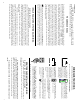
T Xantrex Technology Inc. Toll free 1 800 670 0707 Direct 1 604 422 2777 Fax 1 604 420 2145 CustomerService@xantrex.com www.xantrex.com 445-0197-01-01Rev. 1 Printed in the U.S.A. i4.
TABLE OF CONTENTS Front Panel and Status Lights How the LINK 2000-R Charges Equalizing Cautions! Special Setup for the LINK 2000-R Required Reading Wiring Instructions Standby Regulators Warranty Troubleshooting Flow Chart Wiring Diagram 3 4–5 6 7 8 9–15 15 16 18 19 SUPPLEMENT TO THE LINK 2000 OWNER'S MANUAL THIS DOCUMENT APPLIES TO LINK 2000-R SERIAL NUMBER 5000 AND ABOVE.
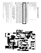
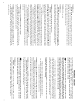
18 Regulator Troubleshooting Flow Chart Most regulation problems can be solved with the following flow chart Terminals #1 through #10 are on the Monitor Terminal Board. Wires referred to by color are in the wiring harness for the Ideal Regulator Output Module NO OUTPUT Do final progress & startup test described on page 14 OK No or variable alternator current Check alternatorbelts, field wire,alternator ground, & field gnd.
HOW THE LINK 2000-R CHARGES See page 18 of LINK 2000 manual for details of the Ideal Charge Curve. Warning: Limitations On Use Please refer to your product user manual for limitations on uses of the product. Specifically, please note that the Link 2000-R is not intended for use in connection with life support systems and Xantrex makes no warranty or representation in connection with any use of the product for such purposes.
16 LIMITED WARRANTY What does this warranty cover? This Limited Warranty is provided by Xantrex Technology, Inc. (“Xantrex”) and covers defects in workmanship and materials in your Xantrex Link 2000-R. This warranty lasts for a Warranty Period of 12 months from the date of purchase at point of sale to you, the original end user customer. This Limited Warranty is transferable to subsequent owners but only for the unexpired portion of the Warranty Period.
EQUALIZING CAUTIONS! Neither the GREEN or the RED LED should be ON when the engine is off! If the RED LED is ON, and the green LED (labeled "ON") is OFF, it is an indication that the FET is shorted or the field is connected to some other source. DO NOT OPERATE THE SYSTEM UNTIL THIS IS RESOLVED! It is now time to start up the engine and see how everything works. For this test make sure the battery charger or any other charging sources are turned off.
14 ASHA TERMINAL (alternator shunt alternator side) YELLOW WIRE must be terminated on the small screw on the alternator side of the alternator shunt. This wire should be connected exactly as described to ensure proper operation. Since this wire is at battery voltage it should be protected with a 2-amp fuse at the shunt as shown; install the fuse after the wiring is connected. No other wires should be connected here.
REQUIRED READING 1) Read the REQUIRED READING section of the LINK 2000 owner's manual. 2) All wiring to the terminal board should be #16 AWG (#14 may be used). The same 8 wire twisted pair cable recommended in the LINK 2000 manual may 3) be used for the LINK 2000-R. The wiring diagram is color coded to this cable. CAUTION! YOU MUST READ THIS SECTION! 4) The LINK 2000-R Ideal Regulator Output Module is designed to replace external "P" type regulators.
12 TERMINAL #10 YELLOW WIRE (B2SHB), is connected to the SMALL SCREW ON THE BATTERY SIDE of the Battery #2 shunt (B2SHB). The TERMINAL #10 YELLOW WIRE and TERMINAL #9 BROWN WIRE should be a twisted pair. PROGRESS CHECK #2 Now it is time to check the battery current function. Plug the meter's ribbon cable into the Monitor Terminal Board and/or insert the fuses. Turn off all DC loads and charging sources. With everything off select Battery #1 or #2 Amps—the LINK 2000-R should read 0.0, -0.
TERMINAL #1 BLACK WIRE (AGND) is the Analog Ground. It is the reference for all measurements. It must be connected on the BSHG (Grounded) side of the battery shunt. The BSHG side of the shunt is the side opposite of the negative battery terminals. It must have a good connection to one of the two #10 screws on the top of the battery shunt. Do not connect anything else to this terminal. TERMINAL #2 is not used. TERMINAL #3 WHITE WIRE (LITE) turns on the monitor backlighting.