INSTALLATION & PROGRAMMING MANUAL ISM4 INTELLIGENT SYSTEM MANAGER
ISM4 INSTALLATION & PROGRAMMING MANUAL 2 TABLE OF CONTENTS INTRODUCTION ....................................................................................................................................................... 3 ISM4 FEATURE DESCRIPTIONS ............................................................................................................................ 4 ISM4 FRONT PANEL FEATURES..........................................................................................................
ISM4 INSTALLATION & PROGRAMMING MANUAL 3 INTRODUCTION Congratulations and thank you for purchasing the Xantech ISM4 Intelligent System Manager. The ISM4 is the answer to the age old problem of simply and inexpensively keeping Home Entertainment System devices in sync. The ISM4 can sync up to four IR controlled devices when referenced to one of those devices, typically a Video Monitor, Home Theater A/V Receiver or Whole House Audio/Video Entertainment System Controller.
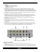
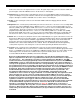
ISM4 INSTALLATION & PROGRAMMING MANUAL 4 ISM4 FEATURE DESCRIPTIONS Figure 1 – ISM4 Front Panel Features ISM4 FRONT PANEL FEATURES 1. IR Learning Eye. The IR Learning Eye allows teaching IR Commands to the ISM4 for programming Source ON and OFF Macros and Command Structures. 2. Source 1-4 LED’s. These LED’s are primarily used to indicate the sensed state of a corresponding system device (Source 1-4). When a sensed device is ON, the LED for that device will illuminate solid green.
ISM4 INSTALLATION & PROGRAMMING MANUAL 5 Edit Mode • Solid Green – Program ON state Macro. • Solid Orange – Program OFF state Macro. • Solid Red – Program Error. 4. Prev Button.
ISM4 INSTALLATION & PROGRAMMING MANUAL 6 IR Receiver and receives IR signals from the receiver. IR signals input on this jack can control the ISM4 and pass through to control the individual sources via the Source 1-4 IR Outputs. 12. IR Control. One 2-circuit (mono) 3.5mm mini jack connects to a normal Emitter Output on an IR repeater system or IR Output on a system controller or A/V Receiver.
ISM4 INSTALLATION & PROGRAMMING MANUAL 7 When Source 1 (System Reference Device) is turned ON, the Sensor Module for that device will show an ON state (+12V) to the Source 1 “Sense In”. The first task that the ISM4 will take is to launch the ON Macro for Source 1. Based on the discussion above, the entire macro will be executed with the exception of the IR content of Command Structure 1. The ISM4 will then ‘look’ at the ON/OFF state of Sources 2-4.
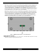
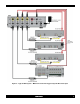
ISM4 INSTALLATION & PROGRAMMING MANUAL Figure 4 – Typical ISM4 System – AV Receiver Triggered Home Theater/IR Receiver Input 8
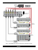
ISM4 INSTALLATION & PROGRAMMING MANUAL Figure 5 – Typical ISM4 System – TV Triggered Home Theater System/IR Receiver Input 9
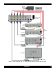
ISM4 INSTALLATION & PROGRAMMING MANUAL Figure 6 – Typical ISM4 System – Multi-Zone Controller Triggered System/IR Control Input 10
ISM4 INSTALLATION & PROGRAMMING MANUAL 11 SYSTEM APPLICATIONS The ISM4 is a versatile device with endless possible applications. For the purpose of this manual, two basic applications will be described. One is a typical Home Theater application with the ISM4 managing system sync for an A/V Receiver and three source components.
ISM4 INSTALLATION & PROGRAMMING MANUAL 12 MULTI-ZONE A/V SYSTEM (Figure 6) The multi-zone configuration provides automatic power management (system sync) when used with a multi-zone system controller that does not feature intelligent source power management. Some multi-zone controllers come equipped with proper, reliable system sync management capabilities (Xantech MRC44/88).
ISM4 INSTALLATION & PROGRAMMING MANUAL 13 INSTALLATION The ISM4 should be installed in the same general location as the system A/V components (A/V Receiver, MultiZone Controller, DVD, SAT, etc). Xantech SM Series Sensor Cables are approximately 6 feet in length and Xantech IR Emitter wires are approximately 10 feet in length, so plan the ISM4 location relative to the other equipment accordingly.
ISM4 INSTALLATION & PROGRAMMING MANUAL 14 2. Either plug the sensor head directly into the A/V Receiver DVD Composite Video Input or connect a shielded female to male RCA-RCA cable with gold ends to the sensor head and then to the AV Receiver DVD Composite Video Input. 3. Plug the SMVID01 3.5mm mini plug into the ISM4 Source 2 “Sense In” Jack. 4. Turn the DVD Player ON. The SMVID01 Status LED should illuminate red. (The Source 2 Status LED on the ISM4 Front Panel should also illuminate green.
ISM4 INSTALLATION & PROGRAMMING MANUAL 15 6. Using a Xantech 10-Foot Mono Cable (Xantech Part No 06017450) connect the Common “IR Out “ on the multi-zone controller to the IR Control Jack on the ISM4 Rear Panel. This will allow IR control of the ISM4 and pass through of IR commands from the multi-zone controller to the source devices. 7. There is no required emitter connection to Source 1 in this application. 8. Label the Sensor and Common IR wires for reference. Source 2 (DVD Player) 10.
ISM4 INSTALLATION & PROGRAMMING MANUAL 16 OTHER CONNECTIONS RS232 This Port connects to the RS232 Output on a system control device such as an A/V Receiver, Multi-Zone Controller, Touch Panel, etc. RS232 Commands input on this port can trigger ISM4 IR output for Source 1 Power (discrete ON/OFF, toggle ON/OFF), Query Source Power State (all sources) and System Info.
ISM4 INSTALLATION & PROGRAMMING MANUAL 17 Figure 8 ISM4 Expansion Connections 1. Using a 1-Foot Mono Cable (Xantech Part No 6017400), connect the Expansion Jack on the Primary ISM4 to the Source 1 “Sense In” on the First Expansion ISM4. 2. If using additional ISM4s, repeat Step 1 for each additional ISM4 as shown in Figure 8. 3. Connect the included Power Supplies, one to each ISM4. 4.
ISM4 INSTALLATION & PROGRAMMING MANUAL PROGRAMMING Programming the ISM4 is similar to manually programming a learning remote. All IR commands are programmed (learned) directly to the ISM4 using the original equipment remotes. There is no PC or programming software requirement.
ISM4 INSTALLATION & PROGRAMMING MANUAL PROGRAMMING MACROS The first step in programming the ISM4 is to fill out the Macro Programming Table. This will help keep track of what device is being programmed for which command with how much delay in which Command Structure within the Source ON or OFF Macro being programmed. Fill out the Table as appropriate for the ISM4 being programmed. It might be advantageous to keep a backup copy of of the table for later use.
ISM4 INSTALLATION & PROGRAMMING MANUAL 20 With the ISM4 powered up and with the IR Emitters attached to the devices to be controlled, program the ISM4 as follows: NOTE: Unless instructed to press a button for a specific duration a button press should be at most one full second.
ISM4 INSTALLATION & PROGRAMMING MANUAL 21 Delay – with additional Command Structures in the Macro 13. To add a delay after the IR Command in Command Structure 1, after Step 5, press the Delay Button. The ISM4 will respond by entering DELAY Learn Mode and the Program LED will flash once. 14. Press the Next Button once for each second of Delay to be added to the Command Structure. Press the Prev Button once for each second of Delay to be subtracted.
ISM4 INSTALLATION & PROGRAMMING MANUAL 22 PROGRAMMING RC68 ON/OFF TRIGGER COMMANDS As noted at the beginning of the Programming Section, one of the ISM4 control options has the ISM4 react to Xantech RC68 IR Commands for Discrete Power ON/OFF or Toggle Power ON/OFF control of Source 1. When using the RC68 Commands, when the ON Button on the system remote is pressed, it will issue the RC68 ON Command.
ISM4 INSTALLATION & PROGRAMMING MANUAL 23 with the RC68 Toggle Command. The System Reference Device (Source 1) and Sources 2-4 should all turn ON. Test OFF 6. With all sources turned ON, test the system by pointing the System Remote toward the ISM4 or connected IR Receiver and press the button with the RC68 Toggle Command. The System Reference Device (Source 1) and Sources 2-4 should all turn OFF. 7. If any functions were ‘missed’, test the individual ON or OFF Macro for that Source.
ISM4 INSTALLATION & PROGRAMMING MANUAL RS232 CONTROL AND PROGRAMMING The ISM4 can be controlled via RS232 to allow power management of the devices controlled by the ISM4 from a PC or appropriately capable system controller. It is important to note that the RS232 capability only allows for Discrete ON/OFF, Toggle ON/OFF as well as Status and System Information. The RS232 Discrete ON/OFF and Toggle Commands allow turning the System Reference Device (Source 1) ON/OFF.
ISM4 INSTALLATION & PROGRAMMING MANUAL system upon detection of a change of state on any Source Sense Input. This feature can be enabled/disabled via the Enable/Disable Automatic Source Power Notification Commands explained in the ISM4 RS232 Command Strings Table above. The Source Power Notification Data String contains Power Status information for all four Sources. The Notification Data Structure is preceded by the ‘#’ character prefix and terminated with the ‘+’ character.
ISM4 INSTALLATION & PROGRAMMING MANUAL 26 {0/1} = Either 0 (zero) or 1 (one); 0 = OFF, 1 =ON CLONING THE ISM4 When necessary, the Macro Table (All Source ON and OFF Macros and their contents) can be cloned from a programmed ISM4 to another ISM4. The cloning process requires a Xantech Null Stereo 3.5mm Mini Cable, (Xantech Part No 06028145). DO NOT USE A STANDARD STEREO MINI CABLE FOR CLONING. To clone an ISM4: 1. Using a Xantech Null Stereo 3.
ISM4 INSTALLATION & PROGRAMMING MANUAL 27 OPERATING THE ISM4 Once setup, there is typically no direct interaction with the ISM4. It will automatically respond to system conditions, IR and RS232 Commands. System ON Mode When the System Reference Device (Source 1) is turned ON, via a power button on the device, an IR remote control, a RS232 Command etc, the ISM4 will detect the change of state (OFF to ON) and automatically enter System ON Mode.
ISM4 INSTALLATION & PROGRAMMING MANUAL 28 RS232 Triggered Commands Externally, the ISM4 will behave in exactly the same manner as described in the Sections: System ON Mode and System OFF Mode, when triggered by RS232 Trigger Commands. Internally if the ISM4 ‘sees’ the RS232 Source 1 ON Command it will look at the state of Source 1. If it is OFF the ISM4 will enter System ON Mode as described. Conversely, if the ISM4 ‘sees’ the RS232 Source 1 OFF Command it will look at the state of Source 1.
ISM4 INSTALLATION & PROGRAMMING MANUAL 29 APPENDIX NAVIGATING AND EDITING MACROS The six Front Panel Buttons each have multiple functions, depending upon the ISM4 Mode. The following sections detail those functions within the different modes. An understanding of the button presses will help make the programming process easier. For the actual programming instructions, see Section: Programming Macros. Normal Operating Mode In Normal Operating Mode the Front Panel Buttons are typically not used.
ISM4 INSTALLATION & PROGRAMMING MANUAL 30 Edit Mode - Navigate Macros Press the Front Panel Prev or Next Buttons and observe the LED’s to navigate Source ON and OFF Macros as follows: Figure 10 Front Panel Navigation – Edit Mode (Navigating Macros) SEQUENCE In Normal Operating Mode, press for 2 seconds (Indicated by the first blink of the Active Source LED) to enter Edit Mode. This will allow navigation of Source ON and OFF Macros.
ISM4 INSTALLATION & PROGRAMMING MANUAL 31 DELAY In EDIT MODE a press of the DELAY button will cause the ISM4 to enter into DELAY Learn Mode. This will allow the programmer to program a delay within a particular IR Command Structure, even if there is no associated IR command in that Command Structure. SEQUENCE In Edit Mode, with a Source ON or OFF Macro selected, press to initiate the IR Learn Mode.
ISM4 INSTALLATION & PROGRAMMING MANUAL NEXT PREV 32 Not used in this IR Learn Mode. If not save of any learned IR is desired, press to return to Edit Mode. Delay Program Mode Press the Front Panel Buttons and observe the LED’s to program Delays in Command Structures as follows: NOTE: Upon entering Delay Edit Mode, the Delay Value is reset to 0 seconds. Figure 12 Front Panel Navigation – Delay Program Mode DELAY NEXT Not used in this Delay Program Mode.
ISM4 INSTALLATION & PROGRAMMING MANUAL SPECIFICATIONS Dimensions 5.25 W x 2.875 D x 1.6525 H (133.35 x 73.025 x 42mm) Weight 0.76 lbs (0.34 kg) Power 2.1mm coaxial jack 12V DC @ 0.5A IR Learning Bandwidth 30KHz-100KHz Macros ON Macros OFF Macros 4 4 Sensor Jacks 4 – Stereo 3.5mm mini jacks Emitter Jacks 4 – 3.5mm mini jacks IR Receiver Jack 1 – Stereo 3.5mm mini jack IR Control In Jack 1 – 3.
ISM4 INSTALLATION & PROGRAMMING MANUAL [ BLANK PAGE ] 34
ISM4 INSTALLATION & PROGRAMMING MANUAL [ BLANK PAGE ] 35
ISM4 INSTALLATION & PROGRAMMING MANUAL 36 Xantech Corporation 13100 Telfair Avenue, 2/F Sylmar, CA 91342 818.362.0353 Tech Support ext. 353 www.xantech.com Installation and Programming Manual, ISM4 Intelligent System Manager © 2008 Xantech Corporation, Document # 08905136B This document is copyright protected. No part of this manual may be copied or reproduced in any form without prior written consent from Xantech Corporation.