INSTALLATION INSTRUCTIONS PA640 SIX CHANNEL POWER AMPLIFIER Amplifiers & Preamplifiers 1
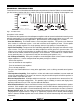
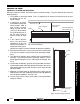
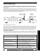
GENERAL INFORMATION To enhance the ease of installation and obtain optimum performance from the PA640, we recommend that you first become familiar with all its features and special capabilities by studying the descriptions and REMOTE ON/OFF POWER ® BRIDGED LEVEL 1V CH1 BRIDGED LEVEL 1V CH2 CH3 BRIDGED LEVEL 1V CH4 CH5 CH6 PA640 SIX CHANNEL POWER AMPLIFIER SYLMAR, CA MADE IN U.S.A. STEREO STEREO 3V .2V 3V LINE INPUTS LINE INPUTS STEREO 3V .2V .2V LINE INPUTS INPUT PANEL Fig.
PA640 PANEL DESCRIPTIONS 2 1 REMOTE ON/OFF POWER ® BRIDGED LEVEL 1V PA640 CH1 BRIDGED LEVEL 1V CH2 CH3 BRIDGED LEVEL 1V CH4 CH5 CH6 SIX CHANNEL POWER AMPLIFIER STEREO STEREO 3V SYLMAR, CA 3V .2V STEREO 3V .2V .2V MADE IN U.S.A. LINE INPUTS LINE INPUTS Fig. 2 PA640 Input Panel – Features and Functions 3 4 5 3 4 LINE INPUTS 5 3 4 5 1. POWER Indicator LED.
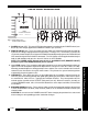
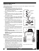
PA640 PANEL DESCRIPTIONS P OW E R MANUAL ON MANUAL OFF (REMOTE ON/OFF) CH6 + – CH4 + – CH5 – + PROTECTION CH3 – + PROTECTION CH2 + – CH1 – + PROTECTION SPEAKER IMPEDANCE 1 2 0 VA C 60 HZ FUSE 5A 9 10 STEREO MODE: 8 Ohms Min. BRIDGED MODE: 16 Ohms Min. + BRIDGED – SPEAKERS 6 7 + BRIDGED – SPEAKERS 6 7 + BRIDGED – SPEAKERS 6 7 8 Fig. 3 PA640 Output & AC Panel – Features and Functions 6. PROTECTION Indicator LED's.
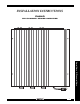
INSTALLATION PHYSICAL LOCATION AND MOUNTING When you mount the PA640, you need to plan its location carefully. Pay close attention to each of the following factors: 1. The amplifier is convection cooled. That is, it depends on the natural free flow of air over the heat dissipating fins for adequate cooling. 2. If mounted in an equipment cabinet or other confining location, allow at least 3 inches of space above the heat sink fins (see Fig. 4).
INSTALLER'S NOTES ____________________________________________________________________________ ____________________________________________________________________________ ____________________________________________________________________________ ____________________________________________________________________________ ____________________________________________________________________________ ____________________________________________________________________________ _______________________________
INSTALLATION (cont'd) CONNECTING THE PA640 I When making connections to the PA640 be sure the power cord is unplugged. Proceed as follows: Stereo Mode Connections 1. Using good quality RCA type patch cables, connect the L and R OUTPUT jacks of the driving preamp to the CH1, CH2, etc. LINE INPUTS jacks on the PA640. Do this for each amplifier pair. Refer to Fig. 6. Preamp Outputs ZPR68, etc. VIDEO 2. Slide the BRIDGED/STEREO switch to the STEREO position. 3.
INSTALLATION (cont'd) Bridged Mode Connections In general, it is recommended that the BRIDGED mode not be used in multi-room applications where several speakers are driven through room volume controls and the like. For such applications, use the STEREO mode. Instead, use the BRIDGED mode for single speaker, higher power applications, such as in surround sound systems. Use speakers with an impedance rating of 8-Ohms minimum.
INSTALLATION (cont'd) Connecting the REMOTE ON/OFF Jack As mentioned under "PA640 PANEL DESCRIPTIONS", the REMOTE ON/OFF jack allows the power to the PA640 to be turned ON and OFF by a remotely applied DC Voltage. Figs. 8 and 9 are typical applications using this feature. Fig. 8 illustrates how a PA640 can be switched ON and OFF via the switched AC outlet on the rear of a preamplifier.
Fig. 9 A Multi-Zone System Using Two PA640's RF IN RF IN XANTECH TV TV S-62/64/66 Wall Speakers MONITOR R L MONITOR R L 780-80 "J" Box IR Receiver ZONE 2 R L Smart Pad 2™ Smart Pad 2™ ZONE 4 ZONE 5 VIDEO IN XANTECH VIDEO IN TV S-62/64/66 Wall Speakers TV MONITOR R L MONITOR R L R L 4-Conductor Home Runs. Smart Pad 2™ Smart Pad 2™ ZONE 1 CAUTION 480-00 Dinky Link™ IR Receiver See "POWER SUPPLY CONSIDERATIONS" in ZPR68-10 Manual, page 10.
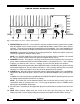
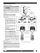
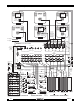
PA640 Fig. 10 Block Diagram (Channels 1 and 2 only) STEREO CH2 Input DISCRETE DRIVER & OUTPUT STAGES + + BRIDGED Feedback PROTECTION LED INPUT LEVEL INVERTER CH1 Input Mute and Protection + CH2 – – CH1 + Protection + + BRIDGED – + + Feedback POWER ON/OFF LED MANUAL OFF (Remote ON/OFF) REMOTE ON/OFF + Power Mute OptoIsolator MANUAL ON PWM Power Supply Fuse 5A 220V AC 120V AC 60 Hz SPECIFICATIONS Number of Channels .........................................................................