INSTALLATION INSTRUCTIONS D5KP DIGI-5 DDS Digital Distribution System OLED Keypad for 1-source and 4-source systems -1-
Safety Information CAUTION: TO REDUCE THE RISK OF ELECTRIC SHOCK, DO NOT REMOVE COVER (OR BACK). NO USER SERVICEABLE PARTS INSIDE. REFER SERVICING TO QUALIFIED SERVICE PERSONNEL. The lightning flash with arrowhead symbol within an equilateral triangle is intended to alert the user to the presence of uninsulated "dangerous voltage" within the product's enclosure that may be of sufficient magnitude to constitute a risk of electric shock to persons.
Damage Requiring Service — These appliances should be serviced by qualified service personnel when: • A power supply connection or a plug has been damaged or • If liquid has been spilled into the appliance or objects have fallen into the appliance or • The appliance has been exposed to water or moisture or • The appliance does not appear to operate normally or exhibits a marked change in performance or • The appliance has been dropped or the enclosure damaged.
1.0 Introduction Exceptional Performance The D5KP is Xantech’s Amplified OLED Controller for the D5SH, D5SH4, D5RH, and D5XH Digital Audio Hub. The D5KP is required to control each zone of a DIGI-5 Digital Distribution System. It provides Source Selection, Volume, Mute and Power control as well as control of all connected audio sources with its built-in IR receiver. Additionally, it provides amplification for the zone’s speakers using an on-board 30 watts per channel Digital amplifier.
Defining Terms Zone A Zone is defined as an area of the house that has separate source selection capabilities from all other areas of the house. Typically, a zone is comprised of a single room, but it is possible for a zone to spread across multiple rooms (kitchen/dining room, master bedroom/master bath) or for multiple zones to be contained in one room (game room/bar area or multiple zones in the yard).
Pre-Wiring D5RH and D5SH, D5SH4 Digital Audio Distribution Hub to D5KP Amplifier Keypad The D5SH4 and all associated components are wired using CAT-5 terminated to the T-568A Wiring Standard (Figure 2.1). When pre-wiring, run lengths of CAT-5 from the pre-determined R5RH and D5SH, D5SH4 Digital Distribution Hub location (the “head-end”) to each Amplifier Keypad location. The CAT-5 routes all audio, power, IR and status information needed for full system operation.
D5IP Local Sources to the D5KP Amplifier Keypad Local sources are only available within the area that they are installed. They will not be available to other areas of the house as they are not distributed by the D5RH, D5SH, or D5SH4. Run lengths of CAT-5 from any local (in-room) source to the Amplifier Keypad located in that area. The D5KP must be connected to an external power supply or a distribution hub (for power).
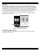
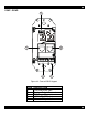
D5KP - FRONT Figure 2.
D5KP - REAR 5 1 4 L+ L- R+ R- 2 - + 3 Figure 2.
Installation The D5KP is designed to mount in a standard single-gang rough-in box (J Box). Typical mounting height is 56-60” from the floor to the bottom of the frame. This provides optimum viewing for the largest number of people. Note: Do not mount the D5KP in the same rough-in box as high voltage devices such as electrical outlets or switches.
3. Connections ZONE OUT – D5RH The ‘ZONE OUT’ RJ-45 connector’s interface with D5KP Amplified Keypad through CAT-5 cables wired to the T-568A Standard. These connectors carry IR information from the keypad as well as audio information to the D5KP Amplifier Keypad. Status information is also carried between the D5RH chassis and the Amplifier Keypads. While a great deal of information is handled by the ‘ZONE OUT’ connections, the connections are straightforward.
ZONE OUT – D5SH, D5SH4 The ‘ZONE OUT’ RJ-45 connector’s interface with D5KP Amplified Keypad through CAT-5 cables wired to the T-568A Standard. These connectors carry IR information from the keypad as well as audio information to the D5KP Amplifier Keypad. Status information is also carried between the D5SH, D5SH4 chassis and the Amplifier Keypads. While a great deal of information is handled by the ‘ZONE OUT’ connections, the connections are straightforward.
Auxiliary Power Connector (AUX POWER OUT) – D5RH and D5SH, D5SH4 For wire runs over 150’, it is recommended to run an additional 16 AWG/2-conductor wire from the head-end location to the Amplified Keypad locations. This will allow the AUX POWER OUT terminals to supply additional power to the Amplifier Keypads to compensate for the additional distance. For wire runs over 300’, 16 AWG/2 conductor wire is required. The maximum wire run using CAT-5 and 16 AWG/2-conductor is 600’.
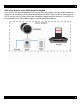
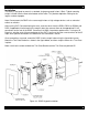
D5IP Source Input Wall Plate Interconnecting between the D5KP and the D5IP Source Input Plate consists of plugging in a CAT-5 cable terminated to an RJ-45 connector wired to T-568A standard (see Figure 2.0) to the RJ-45 jack on the rear of the D5IP. The other end simply plugs into the LOCAL PORT RJ-45 jack on the rear of the zone’s D5KP Amplified Keypad. See Figure 3.2 for details. D5IP Side View D5KP Rear Cat-5 L+ R+ RLSPEAKERS -PWR IN+ Figure 3.
Internal IR Receiver The internal IR receiver is located beneath the ‘X’ button. The internal IR receiver can receive and respond to commands from the D5MR (mini-remote control) and the D5LR (learning remote control). It will also pass-thru IR remote control commands to audio sources via an emitter. An emitter must be connected to the D5IP or the emitter outputs from the D5RH. The internal IR receiver is plasma, LCD, and CFL friendly.
D5KP Speaker Connections The D5RH and D5SH, D5SH4 routes digital audio to connected D5KP Amplifier Keypad where the audio is then amplified and sent to in-room speakers. WARNING!: The D5KP’s amplifier is capable of powering a single pair of 8-6 Ohm speakers. DO NOT connect speakers with a rating of less than 6 Ohms! DO NOT connect more than one speaker to either speaker connector of the D5KP. In doing this, damage to the D5KP may occur and will void the products warranty.
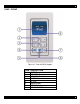
4. D5KP Installer Setup The D5KP Installer Setup is defined into two categories, “User Parameters” and “Setup Parameters”. User Parameters allows the end-user to change the keypad functionality to his or her needs. Setup Parameters are for the installer to custom create an installation based on the end-users requirements. PRESS TO ENTER INSTALLER SETUP PRESS TO ENTER USER SETUP Figure 4.
USER PARAMETERS BASS The “bass” control allows the sound to be adjusted on the lower frequency range. Using the volume bar as an indicator, the central position shows the default position. Moving the indicator to the left side lowers the bass, reducing the volume of the low frequency sound. Moving the indicator to the right side increases the bass, increasing the volume of the low frequency sound. The settings for this control can be adjusted from -5, -4, -3, -2, -1, 0 (default), +1, +2, +3, +4, +5.
USER PARAMETERS (continued) WHOLE HOUSE MUSIC (WHM) Whole House Music mode links all zones to share source selection functionality so that the whole house listens to the same source. Any Keypad in any zone can initiate WHM model. Volume, Mute, and Tone settings remain independent for each zone, but the source selection remains linked.
SETUP PARAMETERS SOURCE NAMES The source names can be changed. Select the source name that is to be changed and press the “X” button. Be default, the source names are “SRC 1”, “SRC 2”, “SRC 3”, “SRC 4”, and “LOCAL”. Use the VOLUME buttons to move the ‘underlining’ cursor to the character that is to be changed. Use the SOURCE buttons to change the character. Once the new name has been established, press the “X” button to return to the SETUP PARAMETERS menu.
SETUP PARAMETERS (continued) INTERNAL IR ENABLE (IR INT) This setting allows the built-on IR Receiver to be disabled if desired. This feature is useful in the builtin IR receiver is being flooded by a plasma TV, compact fluorescent light or sunlight. The Local IR Receiver input on the rear of the unit remains active regardless of this setting. The built-in IR Receiver is enabled by default. The settings for this control can be adjusted from ON to OFF only.
5. Troubleshooting Symptom D5KP does not power up Possible Cause 1. RJ-45 plug crimped incorrectly; or wiring pin-out of RJ-45 reversed. 2. Break in CAT-5 between Zone and “Head-End”. No control or IR sources 1. Wiring: Incorrect wiring between D5KP and D5RH. IR emitter defective at source. IR flooding Intermittent IR source control No audio Loose speaker wires or bad connection. Defective speaker(s) Source(s) not playing audio Zone is in MUTE Distorted Audio Multi-channel digital audio formats (5.
Xantech Limited Warranty (Effective for products sold after July 1, 2006) Xantech Corporation (“Xantech”) warrants to the holder of a valid proof of purchase as the first end-user purchaser (“You”), its products to be free from defects in materials and workmanship for the periods specified below from the date of purchase. This limited warranty extends only to You for product purchased and used in the United States of America.
Specifications Sampling Frequency Audio Resolution Output Power THD + Noise Full Scale Dynamic Range Frequency Response Dimensions DxWxL Weight 48kHz 24 Bit, Stereo 30 Watts Per Channel 0.06% 96dB 20Hz-20kHz +/- 0.1dB 2.62" x 1.8" x 4.07" (66.5 mm x 45.7 mm x 103.4 mm) 6 oz. Unit Weight 12.8 oz. Shipping Weight Xantech Corporation 13100 Telfair Ave. 2F, Sylmar CA 91342 | Xantech.com Installation Instructions, D5KP © 2008 Xantech Corporation Document # 08905194A This document is copyright protected.