HDMI4X4 User Manual www.xantech.
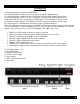
INTRODUCTION Thank you for purchasing the 4x4 HDMI Matrix. The 4x4 HDMI Matrix switches four HDTV sources to any four HDMI displays. The 4x4 HDMI Matrix switcher has four HDMI inputs and four HDMI outputs. Matrix input #1 and the HDMI port of HDTV source #1 connects using a male to male HDMI cable. The HDMI port of HDTV source #2 connects to HDMI input #2. The HDMI port of HDTV source #3 connects to HDMI input #3. The HDMI port of HDTV source #4 connects to HDMI input #4.
OPERATION NOTES READ THESE NOTES BEFORE INSTALLING OR OPERATING THE HDMI4X4 • You should connect all the cables and power supply prior to connecting power to the HDTV sources and 4x4 HDMI Matrix. • When powering the sources, the display needs to point to the source input. • The 4x4 HDMI Matrix is housed in a metal box for better RF shielding. • The 4x4 HDMI Matrix works with all DVI and HDMI displays. • The 4x4 HDMI Matrix supports both AUDIO and VIDEO signals. • The 4x4 HDMI Matrix is fully HDCP compliant.
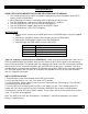
DIP SWITCH GUIDELINES Inside the 4x4 HDMI Matrix is a bank of Dip Switches. Below is a table describing their functions. By default, all switches are set to the Off position.
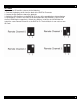
IR CODES In the event of IR conflicts, please do the following: 1. Remove the battery cover from the back of the RMT16-IR remote. 2. Locate the Dip Switches above the batteries 3. Switch the Dip Switches on the RMT16-IR to any of the combinations pictured below. 4. Dip Switches 1 and 2 in the RMT16-IR correspond with Dip Switches 3 and 4 inside the 4x4 HDMI Matrix respectively. Switch the switches inside the 4x4 HDMI Matrix to match the same Remote Channel as the RMT16-IR.
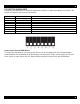
RS232 INTERFACE ASCII 1 2 3 4 5 6 7 8 9 A B C D E F G RS232 Settings Bits per second Data bits Parity Stop bits Flow Control Corresponding RMT16-IR 1 2 3 4 5 6 7 8 9 10 11 12 13 14 15 16 Binary 0011 0001 0011 0010 0011 0011 0011 0100 0011 0101 0011 0110 0011 0111 0011 1000 0011 1001 0110 0001 0110 0010 0110 0011 0110 0100 0110 0101 0110 0110 0110 0111 19200 8 None 1 None -6-
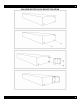
4X4 HDMI MATRIX RACK MOUNT DIAGRAM -7-
TECHNOLOGY TERMINIATION DDC Short form for Display Data Channel. It is a VESA standard for communication between a monitor and a video adapter. Using DDC, a monitor can inform the video card about its properties, such as maximum resolution and color depth. The video card can then use this information to ensure that the user is presented with valid options for configuring the display. DDWG Digital Display Working Group DDWG are the creators of the DVI specification. DVI Digital Visual Interface.
SPECIFICATIONS Video Amplifier Bandwidth Input Video Signal Input DDC Signal Single Link Range HDMI Input/Output Connector Remote Control Port Power Consumption Power Supply Dimensions Shipping Weight 1.65 Gbps 1.2 volts p-p 5 volts p-p (TTL) 1080p / 1920 x 1200 Type A 19-pin Female RS-232 Female, Mini-Stereo 60 watts (max) 24V DC 17” W x 1.75” H x 5.875” D 10 lbs. Technical Support Hours: 7AM-5PM Pacific Phone: 800.843.5465 press 2 for Tech Support Fax: 800.492.6832 email: tech@xantech.