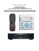
INSTALLATION INSTRUCTIONS MODEL BXAUDIO4X4 FOUR ZONE – FOUR SOURCE COMPLETE AUDIO CONTROLLER/AMPLIFIER SYSTEM
Page: 2 Model BXAUDIO4X4 SAFETY INSTRUCTIONS - READ BEFORE OPERATING EQUIPMENT CAUTION: TO REDUCE THE RISK OF ELECTRIC SHOCK, DO NOT REMOVE COVER (OR BACK) NO USER-SERVICEABLE PARTS INSIDE REFER SERVICING TO QUALIFIED SERVICE PERSONNEL The lightning flash with arrowhead symbol, within an equilateral triangle, is intended to alert the user to the presence of un-insulated “dangerous voltage” within the product’s enclosure that may be of sufficient magnitude to constitute a risk of electric shock to persons
Model BXAUDIO4X4 Page: 3 TABLE OF CONTENTS Section Title Page SAFETY INSTRUCTIONS - READ BEFORE OPERATING EQUIPMENT ........................................................ 2 TABLE OF CONTENTS ................................................................................................................................... 3 SECTION 1.0: GENERAL INFORMATION....................................................................................................... 4 CONTROLLER/AMPLIFIER FEATURES..............
Page: 4 Model BXAUDIO4X4 SECTION 1.0: GENERAL INFORMATION The Xantech BXAUDIO4X4 System, is a whole-house audio distribution, amplification and control system with all the same advanced features as the MRAUDIO4X4 Audio System featuring Xantech’s EZProgramming™ which means no PC is required! The system comes with everything you need for 4 rooms of pure music enjoyment.
Model BXAUDIO4X4 Page: 5 CONTROLLER/AMPLIFIER FEATURES Central Processor • Four Audio Source Inputs • Current sensing (>20mA-<10A) for each input for power management of common source components and using the optional CSM1 Current Sense Module • Four source specific IR emitter ports and one common IR output. • Internal memory (96 Kbytes non-volatile flash) for storing IR codes.
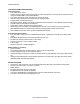
Page: 6 Model BXAUDIO4X4 SECTION 2.0: BXAUDIO4X4 CONTROLLER/AMPLIFIER FEATURE DESCRIPTIONS 1 Figure 1 – Front Panel Figure 2 – The Model BXAUDIO4X4 Controller/Amplifier – Front Panel Features and Functions 1. Front Panel Cover. Snap-in panel decorative panel that covers XPS™ Programming Controls. 2. Program Keypad Button. Activates Program Keypad mode When RUN/PGM switch is set to PGM. 3. Power Management Button. Enables and Disables Intelligent Power Management.
Model BXAUDIO4X4 Page: 7 7. Sequence Button. Pressing the button allows a single additional IR Command to be learned creating a Sequence of Commands (also called a Macro). Up to 5 commands may be programmed in this manner making a macro of up to 6 commands in-all. 8. Delay Button. Adds timed delays in 1 Second increments between IR commands when in Sequence Mode. A Maximum of 7 Seconds may be entered between commands. Delay can only be entered after an initial IR Command is successfully learned. 9.
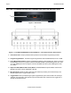
Page: 8 Model BXAUDIO4X4 23 26 27 18 28 24 21 20 25 19 29 16 22 17 Figure 3 –Model BXAUDIO4X4 Controller/Amplifier – Rear Panel Features and Functions 16. Power ON/OFF Switch: Powers Unit ON and OFF when plugged into the proper AC Source. 17. AC Power Input. Standard IEC 3-Conductor AC Line Cord Receptacle for plug-in of a 3-conductor power line cord. 18. Status. Provides a control output of +12 VDC that turns on and off with the zone to drive voltage sensing relay modules and AC strips. (3.
Model BXAUDIO4X4 Page: 9 25. IR Out (Common). 3.5mm Mono Mini Phone Jacks. The Control Amp has a single Common IR Output that can be used to control devices such as motorized drapery systems, Plasma Montior lifts and lighting systems. 26. Sense Inputs. 3.5mm Stereo Mini Phone Jacks for use with the Xantech Model CSM1 Current Sense Module (sold separately). Required for Intelligent Power Management feature. (Tip = 12VDC Out, Ring = Control Sense Input, Sleeve = GND) 27. Com Port. DB9 Connector.
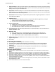
Page: 10 Model BXAUDIO4X4 SECTION 3.0: BXAUDIO4X4 LC4KP KEYPAD FEATURE DESCRIPTIONS 30 34 36 37 31 32 33 35 38 42 39 43 40 44 41 42 Figure 4 –Model LC4KP Keypad – Front Panel Features and Functions 30. BXAUDIO4X4 Keypad. 31. Power. Turns the zone ON and OFF. Can be programmed with IR codes or sequences. 32. IR Sensor. Receives IR from hand-held remotes to control both source components and the BXAUDIO4X4 system.
Model BXAUDIO4X4 Page: 11 39. Vol +. Increases zone volume (non-programmable). 40. Vol -. Decreases zone volume (non-programmable). 41. Mute. Mutes zone speaker output. Sends IR commands programmed to this button (if any) to the selected source and common emitter outputs. 42. CH +. Sends IR commands programmed to this button to the selected source and common emitter outputs. 43. CH -. Sends IR commands programmed to this button to the selected source and common emitter outputs. 44. Status.
Page: 12 Model BXAUDIO4X4 50. Sensor Enable. Jumper. Enables IR sensor on Keypad. Remove when using an external IR receiver. 51. IR Sensitivity Adjustment. Carefully adjust for background light level to prevent false triggering of the IR circuits. Slowly turn counter-clockwise to reduce sensitivity. 52. LCD Backlight Adjustment. Adjusts brightness of LCD backlight. This adjustment does not affect the backlight level for the buttons. Slowly turn counter-clockwise to reduce brightness. 53. Snap-in Pins.
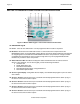
Model BXAUDIO4X4 Page: 13 SECTION 4.0: INSTALLATION OPERATION – OUT-OF-THE-BOX The Controller/Amplifier Out-of-the-Box feature will verify that all sources and zone components are working properly to select and distribute audio prior to XPS™ IR programming. XPS™ Programming for specific components and features follows. 1. Connect BXAUDIO4X4 Controller/Amplifier as shown in Figure 10 to: a) BXAUDIO4X4 Keypads b) Speakers c) AC Power d) Sources e) IR emitters 2.
Page: 14 Model BXAUDIO4X4 LC4KP KEYPAD INSTALLATION INSTRUCTIONS 1. Install standard Dual-Gang J-Box or similar into wall. Note: When installing Keypad next to existing JBox in wall, LCKP J-Box must be mounted 3/8” higher than any adjacent box. 2. Affix LCKP Mounting bracket (P/N 03079875-01) to the Dual Gang J-Box as shown in Figure 6 below using four 8-32 screws (included). 3.
Model BXAUDIO4X4 Page: 15 component and attach the emitter to the sensor window after removing the protective paper cover on the flat side of the emitter head. A common IR jack is also provided for connection to other auxiliary devices. Sense Input Connections The sense input connection will typically be used to sense the power state of a source component using the Xantech CSM1 Current Sense Module. Plug the 3.5mm miniplug from the CSM1 into the appropriate sense jack.
Page: 16 Model BXAUDIO4X4 RJ45 Connector at Controller/Amplifier Cat 5 Cable RJ45 Connector at Keypad Wire Color white/orange orange white/green blue white/blue green white/brown brown Signal Tx+ Tx12V RET IR RET IR +12V Rx+ Rx- Wire Color white/orange orange white/green blue white/blue green white/brown brown Signal Rx+ Rx12V RET IR RET IR +12V Tx+ Tx- Figure 7 - CAT5 Pin Assignments (per EIA/TIA 568B) BXAUDIO4X4 Keypad Cable Connections at the BXAUDIO4X4 Controller/Amplifier 1.
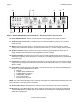
Model BXAUDIO4X4 Page: 17 Primary Keypad Secondary Keypad Application One keypad in Zone with IR Sensor enabled Two Keypads in Zone with IR Sensors enabled One Keypad and one separate IR Receiver in Zone Two Keypads and two separate IR Receivers in Zone (SubZone) Zone Termination Secondary Keypad Sensor Enable OFF ON ON OFF OFF ON OFF ON OFF OFF OFF OFF Secondary Keypad Zone Termination Sensor Enable ON ON ON ON ON OFF Table 1 – LC4KP Keypad Jumper Configurations Multiple Keypad C
Page: 18 Model BXAUDIO4X4 Extended Runs and Secondary Keypad In Zone 400 feet max (122 m) A IR Receiver POWER MRC44 POWER 1 2 3 4 CH VOL PAUSE FOUR ZONE - FOUR SOURCE AUDIO/VIDEO CONTROLLER/AMPLIFIER CH REW SELECT PLAY FF VOL STOP STATUS MUTE 200 feet max (61 m) B POWER IR Receiver POWER MRC44 POWER 1 2 3 4 CH PAUSE VOL CH VOL CH VOL PAUSE FOUR ZONE - FOUR SOURCE AUDIO/VIDEO CONTROLLER/AMPLIFIER CH REW SELECT PLAY FF REW STOP STATUS SELECT PLAY FF VOL STOP
Model BXAUDIO4X4 Page: 19 Speaker Connections SPEAKER PHASING: TO OBTAIN STABLE IMAGING AND FULL BASS RESPONSE, IT IS IMPERATIVE THAT STEREO SPEAKERS BE CONNECTED "IN PHASE" WITH EACH OTHER. YOU CAN VERIFY THIS AS FOLLOWS: 1.
Page: 20 Model BXAUDIO4X4 SAT Receiver AM/FM Tuner To IR OUTs on the To IR OUTs on the BXAUDIO4X4 Controller/Amplifier BXAUDIO4X4 Controller/Amplifier To IR Emitters at A/V Equipment CD Changer XMUSIC AUDIO OUT ZONE 1 To IR OUTs on the BXAUDIO4X4 Controller/Amplifier AUDIO OUT ZONE 2 ZONE 3 TV TV Optional Secondary Keypad POWER POWER CH PAUSE CH REW SELECT PLAY FF VOL CH VOL CH Optional Secondary Keypad PAUSE REW SELECT PLAY FF VOL CH VOL CH POWER PAUSE REW STOP STA
Model BXAUDIO4X4 Page: 21 SECTION 5.0: PROGRAMMING USING XPS™ Point and Shoot IR Learning When programming the BXAUDIO4X4 System, the BXAUDIO4X4 Controller and a single LC4KP keypad plugged into the Zone 1 Keypad port are required as well as the Manufactures remotes for each of the Source Components to be used. All Zones keypads are programmed identically using the Zone 1 Keypad.
Page: 22 Model BXAUDIO4X4 30 34 36 37 31 32 33 35 38 42 39 43 40 44 41 42 Programming Button Layout PROGRAMMING KEYPAD BUTTONS (SINGLE COMMANDS) Note: When learning IR commands into the BXAUDIO4X4 Controller, make sure the IR Learning eye is free from IR interference that might result in IR learning error or intermittent IR commands. IR Interference could be caused by any of the following: Sunlight, Fluorescent light, LCD or Plasma displays, Computer Monitors, EMI etc.. 1. 2. 3. 4. 5. 6. 7.
Model BXAUDIO4X4 Page: 23 PROGRAMMING TIMED DELAYS Timed delays can be placed in-between commands in a sequence in 1 Second intervals for up to a total of 7 Seconds. After a successful IR Command has been learned; 1. Make sure the PROGRAM KEYPAD LED is GREEN and the STATUS LED is OFF. 2. Press the DELAY [8] Button on the front of the BXAUDIO4X4 to enter a 1 Second Delay. 3. The STATUS LED [14] will blink GREEN 4. To add more Delay time, repeat steps 1-3 for a maximum of 7 seconds of delay.
Page: 24 Model BXAUDIO4X4 30 34 36 37 31 32 33 35 38 42 39 43 40 44 41 42 Programming Button Layout PROGRAMMING SOURCE POWER MANAGEMENT With the ability to turn the system ON and OFF from more than one location, the BXAUDIO4X4 Controller needs to know when the different sources are ON or OFF and be able to know when to send or not send power commands to keep the sources in sync with the system. The BXAUDIO4X4 Controller features a Current Sense input for each of the four Source Inputs.
Model BXAUDIO4X4 Page: 25 9. Press the proper SOURCE BUTTON [35, 36, 37, or 38] on the LC4KP Keypad for the Power Management codes to be programmed. Note: the ZONE LED’s 1 thru 4 now will represent SOURCES 1 thru 4. a. The STATUS LED [14] will turn GREEN. 10. Aim the Manufactures Source Remote at the IR Learning eye on the front of the BXAUDIO4X4 [5]. 11. Press and Release the corresponding POWER button on the devices remote.
Page: 26 Model BXAUDIO4X4 4. Press the ZONE (Keypad Source) button to be Linked with . a. The ZONE (Keypad Source) button will flash ORANGE and GREEN. 5. To Link to additional Zones, press the rest of the ZONE (Keypad Source) buttons corresponding to the Zones to be linked to. 6. To switch back to Zones 1 through 4 simply press the Keypad STATUS button again (the Keypad Source Buttons now represent Zones 1 through 4). 7. Repeat steps 3 and 4 until all desired Zones are Linked. To Un-Link Zones: 1.
Model BXAUDIO4X4 Page: 27 SECTION 6.0: EXPANDING THE SYSTEM (Combining 2 BXAUDIO Controllers) The BXAUDIO4X4 System can be expanded to up to eight-zones by linking two Controllers together with the included Expansion ‘Null-Modem’ Cable (Xantech PN#05913560). Expansion Procedure: When expanded the system the following steps must be taken in the following order: 1. Wiring the System (See Expanded Wiring Connections) Note: Do not connect the Expansion cable until after the Master Unit is programmed. 2.
Page: 28 Model BXAUDIO4X4 CONTROLLER1 RI 283TP Emitter SAT Receiver AM/FM Tuner CD Changer XMUSIC 283TP Emitter 283TP Emitter INPUT VIDEO L AUDIO R AV61 16VDC OUTPUTS 1 2 3 4 5 6 VIDEO VIDEO VIDEO VIDEO VIDEO VIDEO L AUDIO R L AUDIO R L AUDIO R L AUDIO R L AUDIO R L AUDIO R AUDIO VIDEO DISTRIBUTION AMPLIFIER ® AV61orY-Cable INPUT VIDEO L AUDIO R AV61 16VDC OUTPUTS 1 2 3 4 5 6 VIDEO VIDEO VIDEO VIDEO VIDEO VIDEO L AUDIO R L AUDIO R L AUDIO R L AUDIO R
Model BXAUDIO4X4 Page: 29 30 34 36 37 31 32 33 35 38 42 39 43 40 44 41 42 Programming Button Layout Configuring the ‘Slave’ Unit (Zones Five through Eight): 1. Enable PROGRAM MODE (Make sure an LCKP4 Keypad is plugged into the Zone 1 Keypad port and the Keypad is ON). 2. Press the PROGRAM KEYPAD button on the front of the BXAUDIO4X4. a. Confirm the PROGRAM KEYPAD LED is illuminated GREEN. 3.
Page: 30 9. 10. 11. 12. Model BXAUDIO4X4 a. When the "PROGRAMMING KEYPAD" LED turns RED, release the "PROGRAMMING KEYPAD" button. Power up the SLAVE unit. a. The SALVE unit will go though the normal power up sequence. b. When the Slave power up sequence ends the Master Zone LEDs will begin to blink RED, the "PROGRAMMING KEYPAD" LED will be RED, and the "STATUS" LED will turn GREEN. c.
Model BXAUDIO4X4 Page: 31 SECTION 8.0: OPERATING INSTRUCTIONS With all system components connected and the BXAUDIO4X4 Controller and Keypads programmed, The system is ready for use. 2 2 3 3 4 5 1 5 14 13 11 6 9 10 1 4 7 6 9 12 7 10 8 11 12 LC4KP Keypad Button Layout MRCREM Remote Button Layout Zone Control Controlling the BXAUDIO System can be done in two ways within the Zone; either by pressing buttons on the LC4KP Keypad or by using the MRCREM Zone Companion Remote.
Page: 32 Model BXAUDIO4X4 NOTE: It is also possible to do all of the above using the included MRCREM Zone Companion remote that is included with the system. Party Mode: To Link 2 or more Zones together simply: 1. Make sure the BXAUDIO System is in RUN Mode Button in the down position. 2. Press and Hold the STATUS button [8] and the CH+ button [6] simultaneously on the Zones Keypad. a. The keypad STATUS LED [13] will begin to flash RED. b.
Model BXAUDIO4X4 Page: 33 SECTION 9.0: SPECIFICATIONS Audio (ea channel) Gain (@ max VC):.................................................................................................................................. Input Overload: ..............................................................................................>2.2 V RMS (@ max VC) Input Impedance: ............................................................................................................... > 20 k Ohms Power Output:....
Page: 34 Model BXAUDIO4X4 SECTION 10.0: WARRANTY Xantech warrants its products to be free of defects in materials or workmanship. This warranty extends for one year from the date of purchase by the consumer. Any products returned freight prepaid to Xantech and found to be defective by Xantech within the warranty period will be repaired or replaced, at Xantech's option, at no charge.
Model BXAUDIO4X4 Page: 35 NOTES: © 2005 Xantech Corporation
Page: 36 Model BXAUDIO4X4 XANTECH CORPORATION 13100 Telfair Avenue, Sylmar CA 91342 phone 818.362.0353 • fax 818.362.9506 www.xantech.com Part No. 08901665 Rev .