
Owner's Manual

INSTALLATION
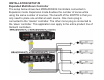
ATTACHING THE EMITTERS TO IR SENSOR WINDOWS
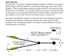
x Each emitter has a clear adhesive layer on the bottom flat surface of
the shell.
x Simply peel off the adhesive cover and affix the emitter to the center
of the IR sensor window on the controlled component’s front panel.
x In some cases it may be difficult to find the location of the IR sensor
on the component. Consult the owner’s manual of the unit, or the
manufacturer, for the exact IR sensor window location.
x Double-sided adhesive tape is included. If you move the emitter to a
different component, use this tape to replace the current adhesive
layer for the best adhesion.
x The shell, though dark in appearance, is transparent to infrared light,
allowing commands from a handheld remote control to pass through
it. This permits direct control of the equipment from a handheld
remote as well as from the 283TPD.
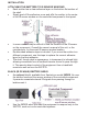
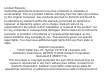
BLACK (IR OPAQUE) EMITTER SHIELD
x An optional shield, available from Xantech as model 28DES, fits over
the emitter head and the sensor window of the controlled component.
It prevents unwanted external IR signals from passing through or
leaking past it.
x Use the 28DES when you want the equipment to respond only to the
283TPD, such as in zone controlled systems.
...
IR&Red
Light
......
Output
~
§W~We,
./
~~~-wi
re
/
Top View
Side
Vi
ew
.....
-
-
IR
&
Red
LLght
Outpllt
(C
ompound
Side)
Cl
ear
, adheslve
l
~er.
(l{.eplacl;!,
if
ne~essar
y,
with a snort
piece
or the
2-si
ded
rape
SLJpplied)
.
Adhe
s
iv
e Layer
Controlled
Component
~C>C>~C>
o
C>C>OOO
000
0 0 0 0
E
mitt
er
\_
Shie
ld
a
nd
E
mitt
er
in
s
tall
ed
over
IR
se
nsor window