d TERMINAL PAYMENT CRADLE XC70-E INSTALLATION GUIDE
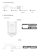
1. PACKAGE CONTENT XC70-E Cable holder*1 Adhesive Sticker*1 Screw*2(M 3x6L) (Optional) 2.
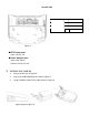
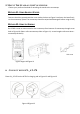
IO PORT SIDE IO PORT AREA Figure 3 ■XC70 Power spec: Input: 12V DC, 2A ■Power Adapter spec: Input: 100 ~240 ac Output: 12V DC, 2A min 3. INSTALLING CABLES 1. Plug in the DC Jack as Figure 4. 2. Plug in the USB/COM/Ethernet cable as Figure 5. 3. Using 2*M3x6L screws to fix cable holder as Figure 6.
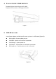
. POWER ON/OFF THE DEVICE To power ON the device:Plug-in the DC JACK To power OFF the device: Un-Plug the DC JACK Figure 7 5.
. MOUNT THE STAND ON THE COUNTERTOP Choose your preferred method of attaching the stand to the countertop. METHOD #1: USING ADHESIVE STICKER Remove the white protectivesticker cover under the base as Figure 9 and press the base firmly to the countertop. (Note: The countertop should be wiped with detergent before using sticker) METHOD #2: USING THE SCREWS Use 2*M3 screws to mount stand on the countertop from bottom of countertop through screw hole as Figure 10.
FEDERAL COMMUNICATION COMMISSION INTERFERENCE STATEMENT This device complies with Part 15 of the FCC Rules. Operation is subject to the following two conditions: (1) This device may not cause harmful interference, and (2) this device must accept any interference erence received, including interference that may cause undesired operation. Note: This equipment has been tested and found to comply with the limits for a Class B digital device, pursuant to Part 15 of the FCC F Rules.