d TERMINAL PAYMENT DEVICE XCL_AT-150 SERIES INSTALLATION GUIDE xCL_AT-150 series: - xCL_AT-150-R3-18U xCL_AT-150-R3-18E
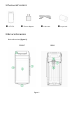
1. PACKAGE CONTENT AT-150 Power adaptor USB cable 2.
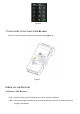
FRONT AREA REAR AREA 1 Printer Paper Cover 2 5” Display 3 Magnetic Strip Reader (MSR) slot 4 Power Button (Press > 3 seconds to power on/off) 5 Smart Card Reader (SCR) slot 6 Charging contact points (Optional) 7 USB port (type C) for charging 8 Battery Compartment ■ AT-150 Power spec: Input: 5V DC, 2A ■ Power Adapter spec: Input: 100 ~240 Vac Output: 5V DC, 2A This symbol is intended to alert the user before starting using the POS.
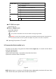
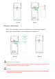
. USING THE MAGNETIC CARD READER Swipe the card through the slot with magnetic stripe side facing the same direction as the display. (Figure 3) Figure 3 (Figure 3) 5. USING THE IC CARD READER Insert an IC card into the slot (Figure 4) with the chip side facing the same direction as the touch panel (Figure 5). Figure 4 Figure 5 6. USING THE KEY PAD After inserting the chip card, Press the numeric key as below keypad (Figure 6) to enter the desirable numbers on touch panel.
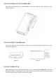
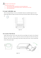
Figure 6 7. USING THE CONTACTLESS CARD READER Tap the contactless card on top of the contactless logo (Figure 7). Figure 7 8. REPLACE THE BATTERY 8-1 REMOVE THE BATTERY STEP 1: Push the latch to pull the bottom cover from AT-150 as Figure 8. STEP 2: After removing the bottom cover, pull up the battery connector as below Figure 9 to change a new battery.
Figure 8 Figure 9 8-2 INSTALL THE BATTERY STEP 1: Insert the battery connector into AT150 with correct direction as Figure 10. STEP 2: After install the battery, close the bottom cover as Figure 11. Figure 10 Figure 11 Bottom Cover Removal Warning When removing the bottom cover and screws for the purposes of changing battery, remember to put back the cover and screws before power on the POS. CAUTION: RISK OF EXPLOSION IF BATTERY IS REPLACED BY AN INCORRECT TYPE.
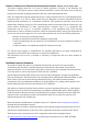
Warning for internal battery pack To reduce risk of fire or burns: 1. Do not attempt to open, disassemble, or service the battery pack. 2. Do not crush, puncture, short external contacts, or dispose of in fire or water. 3. Do not heat above 60 oC 9. INSERT SAM/SIM CARD After removing the battery, the user can find SAM*2 (left) slots and SIM*1(right) slot at the bottom side of device. Please insert the card correctly as the icon shown on the cover as Figure 12: Figure 12 10.
FEDERAL COMMUNICATION COMMISSION INTERFERENCE STATEMENT (Only for xCL_AT-150-R3-18U) This device complies with Part 15 of the FCC Rules. Operation is subject to the following two conditions: (1) This device may not cause harmful interference, and (2) this device must accept any interference received, including interference that may cause undesired operation. Note: This equipment has been tested and found to comply with the limits for a Class B digital device, pursuant to Part 15 of the FCC Rules.