
User's Manual
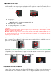
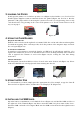

Figure 15 Figure 16
7. INSTALLING THE PRIVACY SHIELD
The privacy shield of the T103P shows as figure 18. We need to tear the tap around the privacy
shield (Figure 19), and please stick the privacy shield on around the 15-key keypad (Figure 20).
The terminal is compliant with PCI privacy screen design requirement when the detachable
privacy shield is installed on the device. Any change to or removal of this privacy shield will
cause security concerns.
Figure 18 Figure 19 Figure 20
Caution: When removing bottom cover for the purposes of cable or SAM card installation, remember to reinstallation the protective cover and make sure to keep
it in place.
Caution: Risk of explosion if the battery is replaced by an incorrect type. Please dispose of used battery according to the instructions.
Warning: This is a Class A product. In a domestic environment this product may cause radio interference in which case the user may be required to take
adequate measures.
Warning: If the device, T103, is used without the detachable privacy shield, the following criteria needs to be met by the Installed Environment of the PED for
complying with the PCI privacy screen design requirement:
A. Positioning of the PED on the check-stand in such way as to make visual observation of the PIN-entry process infeasible.
Visual shields designed into the check-stand.
Position the PED so that it is angled in such a way to make PIN spying difficult.
B. Pop-up (temporary) privacy shield attached to the PED mounting stand. Consumer (through education & prompting) or merchant would put the
shield in place during PIN entry.
C. Installing PED on an adjustable stand that allows consumers to swivel the terminal sideways and/or tilt it forwards/backwards to a position that
makes visual observation of the PIN-entry process difficult.
D. Positioning of in-store security cameras such that the PIN-entry keypad is not visible.
E. Instructing the cardholder regarding safe PIN-entry, done with a combination of:
Signage on the PED.
Prompts on the display, possibly with a "click-through" screen.
Potentially literature at the point of sale.
A logo for safe PIN-entry process.
Table A1: Matrix of Observation Corridors and PIN Protection Method
Observation Corridors
Method Cashier
Customers
in Queue
Customers
Elsewhere
On-Site
Cameras
Remote
Cameras
PED Stand A M H L L L
PED Stand B H H H L M
Check-Stand A L M M L H
Check-Stand B H H M H H
Customer Instruction
H* H* H* H* H*
z Customer Instruction methods are less repeatable and therefore should be used in combination with other methods. L = low , M = medium, H =
high.
Caution: This equipment should be installed and operated with minimum distance 20cm between the radiator & your body. This transmitter must not be
co-located or operating in conjunction with any other antenna or transmitter.
Caution: Use only shielded signal cables to connect I/O devices to this equipment. You are cautioned that changes or modifications not expressly approved by the
party responsible for compliance could void your authority to operate the equipment.
This device complies with Part 15 of the FCC Rules. Operation is subject to the following two conditions: (1) This device may not cause harmful interference, and (2)
this device must accept any interference received, including interference that may cause undesired operation.
Federal Communication Commission Interference Statement
This equipment has been tested and found to comply with the limits for a Class A digital device, pursuant to Part 15 of the FCC Rules. These limits are designed to
provide reasonable protection against harmful interference in a residential installation. This equipment generates, uses and can radiate radio frequency energy and,
if not installed and used in accordance with the instructions, may cause harmful interference to radio communications. However, there is no guarantee that
interference will not occur in a particular installation. If this equipment does cause harmful interference to radio or television reception, which can be determined by
turning the equipment off and on, the user is encouraged to try to correct the interference by one of the following measures:
- Reorient or relocate the receiving antenna.
- Increase the separation between the equipment and receiver.
- Connect the equipment into an outlet on a circuit different from that to which the receiver is connected.
- Consult the dealer or an experienced radio/TV technician for help.