
User's Manual

surge suppressor (recommended) after the power cord is connected to the power adapter. Press the “Cancel”
button at the front of device (Figure 10) until the system is booted up.
Figure 10
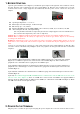
3. LOADING THE PAPER
Gently pop the printer cover’s latch to open the cover (Figure 11); then lift the cover. Load a roll of thermal
paper (Appleton 1012 recommended) into the printer (Figure 12). Load it so that the print-side of the paper will
feed out facing the operator. Close the cover by pressing down evenly on both side tabs, or by pressing on the
center of the printer cover. Use the serrated bar to tear off any excess paper.
Figure 11 Figure 12
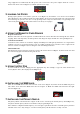
4. USING THE MAGNETIC CARD READER
Magnetic Card Reader
Find the card reader slot at the right side of terminal. Slide the card in either direction through the slot without
stopping. If the card swipe fails, check the position of the magnetic stripe and slide the card again (Figure 13).
Contactless Card Reader
Contactless reader antenna is around the display and PIN pad. It will light up with blue color signal when
terminal is powered on and that means reader is working normally. Put contactless card to approach the
antenna of card reader (Figure 14) for reading the card data during transaction.
Smart Card Reader
The Integrated Circuit Card (ICC) reader is located at the most bottom end (Figure 15). Please make sure that
ICC side is facing upward when inserting into the slot.
Figure 13 Figure 14 Figure 15
5. USING THE KEY PAD
To enter numbers or letters, simply press the appropriate key. For example, to type the letter B: Press and
release [B] twice times, then display shows B (Figure 16).
Figure 16
6. INSTALLING THE SAM CARD
There are four SA M slots located on the left side of the device (Figure 17). Before insert the SAM card, please
turn off the device. Insert the SAM card in the slot in figure 17. Make sure SAM cards inserted in the right
direction (Figure 18).
Figure 17 Figure 18
7. INSTALLING THE PRIVACY SHIELD
The privacy shield of the T103 shows as figure 19. We need to tear the tap around the privacy shield (Figure 20),
and please stick the privacy shield on around the 15-key keypad (Figure 21).
The terminal is compliant w ith PCI privacy screen design requirement when the detachable privacy shield is
installed on the device. Any change to or removal of this privacy shield will cause security concerns.