........................................................................................................................................ General 1 ........................................................................................................................................ Function elements 2 ........................................................................................................................................ Function selection 3 .........................................
1 General 1.1 D19C and D196 densitometer 1.2 Documentation structure 1.3 User 1.4 Safety 1.4.1 Reference signs 1.4.2 Safety information 1.
............................
1.1 D19C and D196 densitometer 1 Dear GretagMacbeth customer, Congratulations! You have just purchased a D19C or D190 densitometer. With its user-friendly operation, high measuring accuracy and rugged design, this unit is a truly unique instrument. You can therefore purchase the densitometer that will exactly meet your requirements. It’s modular design also allows you to order additional functions which are not yet included in your D19C unit at any time later on.
1.2 Documentation structure This operating manual is divided into separate chapters to guide you step by step in the operation of the D190 remission densitometer. Most of the examples in this manual are based on the D196 or the equivalent D19C densitometer. In the manual you find the description of all functions which can be available in the D19C, also those which are not included in the D196.
1.4.2 Safety information ........................................................................................................................................ The D190 remission densitometer is not intrinsically safe. It must therefore not be operated in a hazardous environment. ........................................................................................................................................ ..........................................................................................
2 Function elements 2.1 Overview 2.2 Operating elements 2.2.1 Control ball 2.2.2 Measurement key 2.3 Display 2.4 Menu line symbols 2.5 Setting protection 2.6 Electronic safeguard 2.6.1 Switching on the electronic safeguard 2.6.2 Switching off the electronic safeguard 2.7 Charging the battery 2.7.1 Battery status indication 2.7.1.1 Display for partially discharged battery 2.7.1.2 Display for charged battery 2.7.1.3 Display for fully discharged battery 2.7.2 Charger 2.3.3 Charging procedure 2.
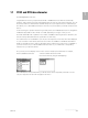
2.1 Overview 2 1 2 3 4 C D19 6 5 7 10 11 8 9 Legend 1 2 3 4 5 6 Control ball Measurement key Display Measuring module Measuring aperture Calibration card 7 8 9 10 11 Charger Charger plug Power cable Data interface Charger socket ............................ Function elements 2.
2.2 Operating elements The unit is operated with two operating elements, the and the . 2.2.1 Control ball The is turned backwards and forwards with the index finger or the thumb. It has the following functions: • Moving the graphics bar for the selection of menu lines on the display.
2.3 Display The high-resolution display allows to show the results of a complete measurement sequence as well as graphic representations. ........................................................................................................................................ To improve the readability of the display the contrast can be adjusted under Settings k Device settings k LCD-contrast. ..................................................................................................................
2.5 Setting protection ........................................................................................................................................ In the D19C you can activate a password protection of your settings (optional feature which is not included in all instruments). ........................................................................................................................................ ....................................................................................
2.6 Electronic safeguard ........................................................................................................................................ The D190 remission densitometer is equipped with an electronic safeguard. It prevents the measuring module from being extended if vibrations occur during transport. ........................................................................................................................................ ..............................................
2.6.2 Switching off the electronic safeguard ........................................................................................................................................ After turning the or after actuating the with the electronic safeguard switched on, a code number for the release of the electronic safeguard will be displayed. ......................................................................................................................................
2.7 Charging the battery ........................................................................................................................................ Battery type refer to Settings k Device Settings k Battery. ........................................................................................................................................ 2.7.1 Battery status indication ......................................................................................................................
2.7.1.3 Display for fully discharged battery ........................................................................................................................................ If the battery is discharged, the unit will display the message ‘battery empty’ and must then be recharged. ........................................................................................................................................ 2.7.2 Charger ....................................................................
3 Function selection 3.1 Overview of functions 3.2 Switching functions on/off 3.3 Function selection 3.
............................
Based on its versatility, the D190 remission densitometer is a unique instrument which decisively optimizes quality control in reprographics. It is designed to perform all conventional measurements and features a wide variety of additional technical improvements. The main menu contains a list of these functions. The selection of a function is carried out with the operating elements and . 3.1 3 Overview of functions The following functions can be selected: 3.
3.3 Function selection • Select the desired menu line by turning the . • Activate the selected function by pressing the . ........................................................................................................................................ The menu line Print header will be displayed if the D190 printer protocol is switched on and if the function print header is activated. ...................................................................................
4 Densitometric functions 4.1 General 4.1.1 Switching functions on/off 4.1.2 Select paper white or absolute white base 4.1.3 Automatic or manual color selection 4.1.3.1 Manual color selection in a densitometric function 4.1.3.2 Automatic color selection in a densitometric function 4.1.4 Printout of measuring results 4.2 Density 4.3 All densities 4.4 Density difference 4.4.1 Procedure if reference values have to be entered first 4.4.2 Procedure with preset reference values 4.
............................ 4.
4.1 General 4.1.1 Switching functions on/off ........................................................................................................................................ The functions can be switched on/off under Settings k Device settings k Available functions (refer to 6.5) Switched-off functions will not be shown in the main menu! Functions not available in your instrument will also not be shown in the main menu! ............................................................................
4.1.3.2 Automatic color selection in a densitometric function Procedure: • Select the menu line Color by turning the and confirm the selection by pressing the . • Select the automatic color selection. • Activate the automatic color selection by pressing the . 4.1.4 Printout of measuring results Procedure: • Configure your printer interface with the corresponding operating manual. ............................................................................
4.2 Density ........................................................................................................................................ Select paper white or absolute white base under Settings k Measurement parameters k White base. ........................................................................................................................................ ................................................................................................................................
4.3 All densities The function ‘All densities’ will be used if you are interested in all absorbtions of a printed color, not only the main absorbtion (e.g. for measuring the gray-balance). ........................................................................................................................................ Select paper white or absolute white base under Settings k Measurement parameters k white base. .......................................................................................
4.4 Density difference ........................................................................................................................................ Select paper white or absolute white base under Settings k Measurement parameters k White base. ........................................................................................................................................ .....................................................................................................................
• Position the measuring aperture on the color samples Black, Cyan, Magenta and Yellow, and initiate the measurements by pressing the . • • • • • • Select the entry line to be corrected by turning the and confirm the selection by pressing the . • The entry field for the density reference value appears on the display. • Correct the density reference value by turning the and terminate the entry by pressing the .
• Position the measuring aperture on the color sample and initiate a measurement by pressing the . • The measured density difference ∆D appears on the display. If the preset tolerance value for the density difference is exceeded, the note Out of tolerance will additionally be shown. • Select the menu line Return by turning the and actuate the to return to main menu. 4 ............................ Densitometric functions 4.4.
4.4.2 Procedure with preset reference values ........................................................................................................................................ Define the names of your jobs and the number of references per job under Settings k Jobs. ........................................................................................................................................ .....................................................................................................
4.5 All density differences The function ‘All density differences’ will be used if you are interested in the differences of all absorbtions of a printed color, not only the main absorbtion (e.g. for measuring the gray-balance). ........................................................................................................................................ Select paper white or absolute white base under Settings k Measurement parameters k White base. ................................................
• Select the menu line Measure paper white by turning the . • Position the measuring aperture on the paper white and initiate a measurement by pressing the . • The display White measurement done is shown for about 1 second. • Select the menu line Measure ‘color’ by turning the . • Position the measuring aperture on the color sample and initiate the measurements by pressing the .
• Select the menu line Accept data by turning the . • Accept the reference and tolerance values by pressing the . • Select the menu line Measure paper white by turning the . • Position the measuring aperture on the paper white and initiate a measurement by pressing the . • The display White measurement done is shown for about 1 second.
4.5.2 Procedure with preset reference values ........................................................................................................................................ Define the names of your jobs and the number of references per job under Settings k Jobs. ........................................................................................................................................ .....................................................................................................
4.6 Dot gain ........................................................................................................................................ Select automatic or manual filter selection under Settings k Color or in the selected densitometric function under the menu line Color. ........................................................................................................................................ .......................................................................................
• Position the measuring aperture on the 80% halftone patch and initiate a measurement by pressing the . • The display shows the dot gain of the 80% halftone patch. • Position the measuring aperture on the 40% halftone patch and initiate a measurement by pressing the . • The display shows the dot gain of the 40% halftone patch. • Select the menu line Return by turning the and press the to return to the main menu. ...........................
4.7 Print characteristic ........................................................................................................................................ Select automatic or manual filter selection under Settings k Color or in the selected densitometric function under the menu line Color. ........................................................................................................................................ ...........................................................................
• After pressing the , the graphic mode is shown on the display. • Pressing the again will switch the display to the numerical mode. • Select the menu line Return by turning the and press the to return to the main menu. 4.7.1 Print out of the print characteristic ........................................................................................................................................
4.8 Dot area ........................................................................................................................................ Select automatic or manual filter selection under Settings k Color or in the selected densitometric function under the menu line Color. ........................................................................................................................................ .......................................................................................
• Select the menu line Return by turning the and press the to return to the main menu. ............................ 4.
4.9 Printing plate The function ‘printing plate’ is used for measuring the dot area on printing plates for offset printing. The operating procedure is similar to the procedure of the function ‘dot area’, but instead of the paper white you have to measure the plate ground of the printing plate. The measurements of the solid tone and halftone have to be performed on the corresponding fields on the printing plate. The calculations of the dot area is done using the are the Yule-Nielsen.
• Select the menu line Return by turning the and press the to return to the main menu. ............................ 4.
4.10 Contrast ........................................................................................................................................ Select paper white or absolute white base under Settings k Measurement parameters k White base. ........................................................................................................................................ ...............................................................................................................................
4.11 Trapping ........................................................................................................................................ Select paper white or absolute white base under Settings k Measurement parameters k White base. ........................................................................................................................................ ...............................................................................................................................
4.12 Hue error ........................................................................................................................................ Select paper white or absolute white base under Settings k Measurement parameters k White base. ........................................................................................................................................ Procedure: • Select the menu line Hue error by turning the .
4.13 Greyness ........................................................................................................................................ Select paper white or absolute white base under Settings k Measurement parameters k White base. ........................................................................................................................................ Procedure: • Select the menu line Greyness by turning the .
4.14 Auto. function 1 ........................................................................................................................................ Auto. function 1 includes the automatic color recognition (Automatic) and the automatic function recognition for density, dot gain and trapping. The display indicates the printing sequence with the density values of the standard colors and the corresponding measured values for density, dot gain or trapping. ...........................................
• Position the measuring aperture on a solid tone patch, a halftone patch or an overprint patch and initiate a measurement by pressing the . • The display indicates the printing sequence with the density values of the standard colors and the corresponding measured values for density, dot gain or trapping. • Select the menu line Return by turning the and press the to return to the main menu. ..................................................................
4.15 Auto. function 2 ........................................................................................................................................ Auto. function 2 includes the automatic color recognition (Automatic) and the automatic function recognition for density, dot gain and trapping. The display indicates the printing sequence with the density values of the standard colors and the corresponding measured values for density, dot gain or trapping at the same time. ..........................
• Position the measuring aperture on the standard colors in the given printing sequence and initiate a measurement of each color by pressing the . • The display indicates the solid tone density values of the standard colors; the printing sequence is shown in brackets; in the example: B ( 4 ), C ( 1 ), M ( 2 ), Y ( 3 ). • • • • • • Position the measuring aperture on a solid tone patch, a halftone patch or an overprint patch and initiate a measurement by pressing the .
4.15.1 Print out of the measuring results ........................................................................................................................................ • • • • Configure and connect your printer to the D190 remission densitometer. Configure data interface under Settings k Data interface. Select the D190 printer protocol under Settings k Printer k Printer protocol. Return to the main menu. ..........................................................................................
5 Settings 5.1 Overview 5.1.1 Function selection 5.1.1.1 Function selection if the settings are not protected 5.1.1.2 Function selection if the settings are protected 5.2 Color 5.2.1 Manual color selection 5.2.2 Automatic color recognition 5.3 Jobs 5.3.1 5.3.2 5.4 5.5 Job definition 5.3.1.1 Accept data 5.3.1.2 Setting of default values 5.3.1.3 Reject data Job selection References 5.4.1 Reference entry by measurement 5.4.1.1 Accept data 5.4.1.2 Reject data 5.4.
5.5.5 5.5.6 Measurement parameters for dot area 5.5.5.1 Setting for dot area calculation according to Murray-Davies 5.5.5.2 Setting for dot area calculation according to Yule-Nielsen Measurement parameters for printing plate 5.5.6.1 Setting of the Yule-Nielsen coefficient for measuring printing plates 5.6 Calibration 5.6.1 GretagMacbeth calibration cards 5.6.2 Calibration with paper white base 5.6.2.1 Reject data 5.6.3 Check calibration with paper white base 5.6.4 Calibration with absolute white base 5.
5.
5.1.1.1 Function selection if the settings are not protected Procedure: • Select the menu line Settings by turning the and confirm the selection by pressing the . • Select the desired menu line by turning the and confirm the selection by pressing the . ............................ 5.1.1.
5.1.1.2 Function selection if the settings are protected Procedure: • Select the menu line Settings by turning the and confirm the selection by pressing the . • Press the again for entering the password. • Select the characters of the password by turning the and confirm the selections by pressing the .
5.2 Color ........................................................................................................................................ The setting for automatic or manual color selection can also be made in the menu line Color of the densitometric functions. ........................................................................................................................................ 5.2.1 Manual color selection Procedure: • Select the menu line Color by turning the .
5.2.2 Automatic color recognition Procedure: • Select the menu line Color by turning the . • Activate the selected function by pressing the . • Select the menu line Automatic by turning the . • Activate the automatic color recognition by pressing the . • The menu line Return is shown in reverse video on the display. • Press the to return to the next higher menu level. 5 ............................ Settings 5.2.
5.3 Jobs ........................................................................................................................................ For density difference measurements, it is necessary to measure or enter reference values. Tolerance values can be overwritten. Four jobs with four to eight references each can be defined. The names of the jobs can be freely selected. The names of the references one to four are preset. The names of the references five to eight can be freely selected.
• Delete the current job name by repeatedly pressing the . • Enter the new job name with the . • Select the menu line OK with the and press the . • The display shows in reverse video, i.e. the reference with the name GRETAG-01 is switched off. • Enter the number of reference values you wish to store under the name GRETAG-01. Four to eight reference values can be stored. • Terminate the entry by pressing the . 5 5.3.1.
5.3.1.2 Setting of default values Procedure: • Select the menu line Set default values by turning the and press the . • The display shows No in reverse video. • Press the if you wish to terminate the procedure. • Select Yes by turning the . • Press the if you wish to set default values. • The display shows Accept data in reverse video. • Press the to set all jobs to the default values. 5.3.1.
5.3.2 Job selection Procedure if jobs have already been defined: • Select the menu line Select job by turning the . • Activate the selected function by pressing the . • The display shows a table with the names of previously defined jobs. • Select the desired job by turning the and confirm the entry by pressing the . • The display shows Return in reverse video. • Press the several times to return to the main menu. 5 .........
5.4 References ........................................................................................................................................ For density difference measurements, it is necessary to measure or enter reference values. Tolerance values can be overwritten. Four jobs with four to eight references each can be defined. The names of the jobs can be freely selected. The names of the references one to four are preset. The names of the references five to eight can be freely selected.
• The display shows White measurement done for about 1 second. • Then the display shows Measure color in reverse video. • Position the measuring aperture on the color samples Black, Cyan, Magenta and Yellow, and initiate the measurements by pressing the . 5.4.1.1 Accept data Procedure: • Accept the reference values by pressing the . • The display shows Return in reverse video. • Press the several times to return to the main menu. 5.4.1.
5.4.2 Assignment of measured values to reference values ........................................................................................................................................ The measured values can be assigned either to a specific reference value or they can be automatically assigned to the “nearest” reference value. ........................................................................................................................................ 5.4.2.
5.4.2.2 Automatic assignment of measured values to references Procedure if no jobs have been defined: • Select the menu line References by turning the and confirm the selection by pressing the . • Select the menu line Reference. • Activate the function by pressing the . • The display shows a table with the menu lines Automatic, Black, Cyan, Magenta and Yellow. • Select Automatic by turning the .
5.4.3 Entry or correction of reference and tolerance values ........................................................................................................................................ After entering reference or tolerance values, the current values are indicated in the respective entry fields. ........................................................................................................................................
5.4.3.1 Accept data Procedure: • Accept the reference values by pressing the . The new data are stored. • The display shows Return in reverse video. • Press the several times to return to the main menu. 5.4.3.2 Reject data Procedure: • Select the menu line Reject data by turning the and confirm the action by pressing the . The new data will not be stored; stored data are retained. • The display shows the menu line Return in reverse video.
5.4.4 Job selection Procedure if jobs have been defined: • Select the menu line References by turning the and confirm the selection by pressing the . • The display shows Reference in reverse video. • Activate the function by pressing the . • The display shows Automatic in reverse video. • Select the menu line Job : Job... l by turning the and confirm the selection by pressing the .
5.4.5 Reference entry Procedure: • Select the menu line Reference entry by turning the and confirm the selection by pressing the . • Activate the function by pressing the . • The display shows Measure paper white in reverse video. • Position the measuring aperture on the paper white and initiate a measurement by pressing the . • The display White measurement done is shown for about 1 second.
5.4.5.1 Accept data Procedure: • Accept the reference values by pressing the . • The display shows Return in reverse video. • Press the several times to return to the main menu. 5.4.5.2 Reject data Procedure: • Select the menu line Reject data by turning the and confirm the action by pressing the . The new data will not be stored; stored data are retained. • The display shows the menu line Return in reverse video.
5.5 Measurement parameters 5.5.1 Overview In the menu Measurement parameters, the following settings can be made: • Selection of paper white or absolute white as white base. • Entry of one to three halftone reference values for dot gain measurements. • Entry of the halftone wedge gradation and the presetting for numerical or graphic representation of the print characteristic.
5.5.2 Measurement parameters for white base ........................................................................................................................................ The white base can be set to paper white or absolute white. ........................................................................................................................................ 5.5.2.1 Setting of paper white base Procedure: • Select the menu line White base by turning the .
5.5.3 Measurement parameters for dot gain ........................................................................................................................................ One to three halftone reference values in the range between 0% and 100% can be entered. At the upper and lower ends of this range, the selected halftone values can be switched off. This will be confirmed with on the display. ....................................................................................................
• Select the menu line 3.Screen percent and confirm the selection by pressing the . • The display shows the entry field for the 3rd halftone reference value. • Enter the 3rd halftone reference value by turning the and confirm the entry by pressing the . 5.5.3.1.1 Accept data Procedure: • Select the menu line Accept data by turning the and confirm the action by pressing the .
5.5.4 Measurement parameters for print characteristic ........................................................................................................................................ Entry of the halftone step wedge graduation in the range between 5% and 99%. Presetting for the numerical or graphic representation of the print characteristic. ........................................................................................................................................ 5.5.4.
5.5.4.2 Numerical or graphic representation of print characteristic ........................................................................................................................................ The presetting for numerical or graphic representation of the print characteristic determines the type of representation that will be used with the densitometric function Print characteristic. This function also allows to switch between the representation types. ..........................................
5.5.5 Measurement parameters for dot area ........................................................................................................................................ Selection of the desired formula for the dot area calculation according to Murray- Davies or Yule-Nielsen and entry of the Yule-Nielsen coefficients for Black, Cyan, Magenta and Yellow. ........................................................................................................................................ ........
• The entry field for the Yule-Nielsen coefficients is shown on the display. • Select the desired color for example Black by turning the and confirm the selection by pressing the . • Press the ; the Y-N coefficient for Black is shown in reverse video on the display. • Enter the Y-N coefficient for Black with the and confirm the entry by pressing the . • Enter the Y-N coefficients for Cyan, Magenta and Black as described above.
5.5.6 Measurement parameters for printing plate ........................................................................................................................................ The light trap effect will be corrected by using the Yule-Nielsen formula for the calculation of the dot area of printing plate. The Yule-Nielsen coefficient has to be entered. On most printing plates you achieve good results with coefficient values from 1.08 to 1.24 (typically 1.15).
5.6 Calibration ........................................................................................................................................ The unit can be calibrated with paper white base or with absolute white base. The desired white base, paper white or absolute white, can be selected in the menu Settings k Measurement parameters k White base. ........................................................................................................................................
5.6.2 Calibration with paper white base Procedure: ........................................................................................................................................ Select paper white base under Settings k Measurement parameters k White base. ........................................................................................................................................
• Press the to get into the entry field of the color Black. • Turn the to correct the calibration value until it corresponds with the target value indicated on the calibration card. • Terminate the entry by pressing the . • Correct the calibration values of the colors Cyan, Magenta and Yellow one after the other. • The graphics bar jumps to the menu line Accept data. • Store the calibration data by pressing the .
5.6.3 Check calibration with paper white base Procedure: ........................................................................................................................................ Select paper white base under Settings k Measurement parameters k White base. ........................................................................................................................................
• Position the measuring aperture on the color fields to be measured and initiate a measurement each by pressing the . • The calibration values and the corresponding colors appear on the display one after the other. • Compare the calibration values with the target values on the calibration card. If the values agree or if the difference is not more than ± 0.02 D, it is not necessary to recalibrate the densitometer.
5.6.4 Calibration with absolute white base Procedure: ........................................................................................................................................ Select absolute white base under Settings k Measurement parameters k White base. ........................................................................................................................................
• Position the measuring aperture on the paper white and initiate a measurement by pressing the . • The display shows White measurement done for about 1 second. • Then the request Measure color is shown on the display. • Position the measuring aperture on the color fields to be measured and initiate a measurement each by pressing the . • The uncorrected calibration values and the corresponding colors appear on the display one after the other.
• Press the to get into the entry field for the color Black. • Turn the to correct the calibration value until it corresponds with the target value indicated on the calibration card. • Terminate the entry by pressing the . • Correct the calibration values of the colors Cyan, Magenta and Yellow one after the other. • The graphics bar then jumps to the menu line Accept data. • Store the calibration data by pressing the .
5.6.5 Check calibration with absolute white base Procedure: ........................................................................................................................................ Select absolute white base Setting k Measurement parameters k White base. ........................................................................................................................................
• After the color Yellow has been measured, and if all calibration values are within the specified tolerance, the graphics bar will jump to the menu line Return. • Press the several times to return to the main menu. 5 ............................ Settings 5.6.
5.7 Printer The D190 remission densitometer can be connected to different types of printers or computers. ........................................................................................................................................ The D190 and the printer must be configured correctly. • Printout of measuring results (refer to chapter 4.1.4). • Baudrate setting (refer to chapter 5.8.1). • Handshake setting (refer to chapter 5.8.2).
• Activate the selected function by pressing the . • Select the desired type of printer or PC by turning the and confirm the selection by pressing the . • Select the menu line Return and press the several times to return to the main menu. 5.7.2 Printer protocol ........................................................................................................................................
• • • • The display shows the menu lines No, D180 and D190 Select the desired menu line by turning the . Activate the selected function by pressing the . Select the menu line Return and press the several times to return to the main menu. ........................................................................................................................................
5.7.4 Header printout If the D190 protocol is selected and the function ‘Print header’ is activated, the function Print header is shown in the main menu. By pressing the a header which is helpful for a perfect documentation of your measuring results will be printed. The header can be individually defined and can show information about your customer, your job, your company, the operator, date and time and the reference values.
5.7.4.1.1 Printing date and time All D19C and all D196 densitometers manufactured after 1.1.1995 have a built-in-clock. These instruments are able to print out date and time of the header printing. Procedure: • Select the menu Settings k Printer k Header. • Select the menu line Date and time by turning the and confirm the selection by pressing the . • Select on or off by turning the and confirm the selection by pressing the . 5.7.4.1.
5.7.4.1.3 User specifications Procedure: • Select the menu Settings k Printer k Header. • Select the menu line User specification by turning the and confirm the selection by pressing the . • Press the to get into the selection field for the User name. • Select the desired user (User1 ....User8) by turning the and confirm the selection by pressing the . • Select e.g.
• The display shows the first line of the entry field after pressing the . • Select the menu line o by turning the and delete the actual firm name by repeatedly pressing the . • Enter the new firm name: • Select entry line with . • Terminate entry with . • Select the menu line OK and terminate the entry by pressing the . • The display shows now the second line of the entry field; and so on.
5.8 Data interface ........................................................................................................................................ The D190 remission densitometer features a serial RS232 interface with adjustable baud rate. The following settings are available: No handshake, Software handshake (Xon/Xoff) or Hardware handshake. ........................................................................................................................................ ...................
5.8.2 Handshake setting Procedure: • Select the menu line Handshake by turning the and confirm the selection by pressing the . • Select the desired operating mode Xon/Xoff, Hardware or No by turning the . • Activate the selected function by pressing the . • Select the menu line Return by turning the and press the several times to return to the main menu. ............................ 5.8.
6 Device settings 6.1 Overview 6.1.1 Function selection 6.2 Turn display 6.3 LCD contrast 6.4 Decimal places 6.5 Available functions 6.5.1 All functions 6.5.2 User-defined functions 6.5.3 New functions 6.6 Setting protection 6.6.1 Activate the setting protection 6.7 Battery 6.7.1 Battery type 6.8 Date and Time 6.8.1 The menu date and time 6.8.2 Select the format of date and time 6.8.3 Set date 6.8.4 Set time 6.8.5 Clock adjustment 6.9 Service 6.9.1 Measuring system 6.9.1.
............................
6.
6.1.1 Function selection • Select the menu line Settings by turning the and confirm the selection by pressing the (setting protection refer to 5.). • Select the menu line Device settings by turning the and confirm the selection by pressing the . • Select the desired menu line by turning the . • Activate the selected function by pressing the . ............................ 6.1.
6.2 Turn display ........................................................................................................................................ The display of the D190 remission densitometer can be reversed 180°. In this way, the unit can be operated with either the left or the right hand. ........................................................................................................................................
6.4 Decimal places ........................................................................................................................................ The resolution of the density values displayed by the D190 remission densitometer can be defined by the user. Density values can be displayed with one to three decimal places. ........................................................................................................................................
6.5 Available functions ........................................................................................................................................ The user of a D190 remission densitometer can activate or densitometric functions. Only activated functions wil be displayed in the main menu. Also the menus for the settings of these functions are not shown.
6.5.2 User-defined functions ........................................................................................................................................ The user can define which functions are selectable in the main menu of the D190. ........................................................................................................................................
6.5.3 New functions ........................................................................................................................................ If you are an owner of a D19C, you can bye additional functions for your instrument. You can bye and enter all functions described in this manual into your D19C. This is possible at least 10 years after delivery of the instrument. If you buy a new function you get a code number which has to be entered into the D19C.
6.6 Setting protection ........................................................................................................................................ In the D19C you can protect the settings by means of a password (optional feature which is not included in all instruments). ........................................................................................................................................ ........................................................................................
6.7 Battery ........................................................................................................................................ The D190 remission densitometer can be operated with either nickel-cadmium or nickel-metal hydride batteries. ........................................................................................................................................ ..................................................................................................................
6.8 Date and time All D19C and all D196 densitometers manufactured after 1.1.1995 have a built-in-clock. These instruments are able to print out date and time of the measurements. You can set and adjust the clock and you can choose the time format. 6.8.1 The menu Date and time Procedure: • Select the menu Settings k Device settings. • Select the menu line Date and time by turning the and confirm the selection by pressing the . 6.8.
6.8.3 Set date Procedure: • Select the menu Settings k Device settingsk Set date and time (refer to 6.8.1). • Select the menu line Set date by turning the and confirm the selection by pressing the . • Select the menu line Day by turning the and confirm the selection by pressing the . • Enter the day by turning the and confirm the selection by pressing the . • Proceed in the same way for entering month and year.
6.8.5 Clock adjustment The internal clock can be adjusted. If the clock of your instrument is to fast e.g. 2 seconds per day the setting value in sec/day should be corrected by -2.0. Procedure: • Select the menu Settings k Device settingsk Set date and time (refer to 6.8.1). • Select the menu line Clock adjustment by turning the and confirm the selection by pressing the .
6.9 Service ........................................................................................................................................ The software of the D190 remission densitometer has different capabilities for servicing the instrument (test features and initialization). In normal application, this features are not used by the operator. ........................................................................................................................................
6.9.1.1 Switching the lamp on/off Procedure: • Select the menu line Lamp by turning the . • Press the ; the display shows . • Switch the lamp on or off by turning the . • Press the ; the display shows Lamp in reverse video. • Select the menu line Return by turning the and press the several times to return to the main menu. 6.9.1.
6.9.1.3 Measurement counter The measurement counter indicates the number of performed measurements. ........................................................................................................................................ The measurement counter is reset to zero with the function Initialize device . See Settings k Device settings k Initialize device . ........................................................................................................................................ 6.
6.10 Type data ........................................................................................................................................ The storage of the D190 remission densitometer contains unit-specific data. ........................................................................................................................................ ........................................................................................................................................
6.11 Electronic safeguard ........................................................................................................................................ The D190 remission densitometer is equipped with an electronic safeguard. It prevents the measuring module from being extended if vibrations occur during transport. ........................................................................................................................................ ..............................................
6.11.2 Switching off the electronic safeguard ........................................................................................................................................ After turning the or pressing the with the electronic safeguard switched on, a code number for the release of the electronic safeguard will be displayed. ........................................................................................................................................
6.12 Language ........................................................................................................................................ The D190 remission densitometer offers a selection of different operating languages. ........................................................................................................................................ ........................................................................................................................................
7 Help 7.1 Texts in a foreign language 7.2 No measurements can be performed 7.3 Desired function cannot be found 7.4 Doubtful measuring results 7.5 Bad readability of the display 7.6 Printer does not print or no communication with the computer 7.
............................
7.1 Texts in a foreign language Procedure to refind the menu Language (refer to 6.12.2) 7.2 No measurements can be performed No measurements can be performed with an activated safe guard for transportation (refer to 6.11.2 Switching off the electronic safe guard). 7.3 Desired function cannot be found Non active functions cannot be selected in the main menu. Activation or deactivation of measuring functions refer to 6.5 Available functions. The densitometers D190 contain different numbers of functions.
7.6 Printer does not print or no communication with the computer • Check connections: Check connections between D190 and printer or computer • Check power supplies: Check power supplies of printer or computer. • Check D190 settings: - Printer or computer protocol selected k refer to 5.7.2 Printer protocol. - Printer type selection O.K. k refer to 5.7.1 Printer or PC. - Baudrate setting O.K. k refer to 5.8.2. - Handshake setting O.K. k refer to 5.8.2.
7.7 Messages ........................................................................................................................................ Messages are shown on the display as follows: Message: (1...n) Brief description Message numbers in brackets are not shown on the display. ........................................................................................................................................
Message No. Message on display Error source Reméde 23 Not calibrated Missing calibration values Calibrate instrument 24 Temperature failure The instrument’s temperature exceeded the limit of 50°C during the charging of the battery. The ambient temperature was to high. Charge the battery at room temperature conditions (25) Measure different color The same color was measured two times in the trapping function.
Message No.
............................ 7.
8 Maintenance 8.1 Battery replacement 8.2 Adjustment of the measuring aperture 8.
............................
........................................................................................................................................ The D190 remission densitometer can be operated either with a nickel-cadmium or a metal-hydride battery. The battery type is coded on the connector and will be registered by the software. ........................................................................................................................................ .................................................
8.3 Replacement of measuring lamp and tube U Procedure: • Undo mounting screws and remove measuring aperture. • Manually set adjustment knob to position A. • Withdraw measuring module manually until adjustment knob is in position B (matched arrows). • Undo screws and remove tube. • Replace lamp module (snap connection). • Insert tube and screw tight. • Install and then adjust measuring aperture (see chapter 8.2). ............................ 8.
9 Options 9.1 Overview 9.2 Measuring functions 9.3 Printers 9.4 Cases 9.5 Filter sets 9.6 Optical tubes 9.7 Measuring lamps 9.8 Calibration cards 9.9 Measuring apertures 1 2 3 4 9.10 Rechargeable batteries 9.11 Chargers 9.12 Data cables and converters 9.12.1 Connection to printer or PC 9.12.
............................
9.1 Overview ........................................................................................................................................ Available options: • Measuring functions ( for D19C) • Printers • Cases • Filter sets according to DIN or ANSI standards • Optical tubes for measurements with or without polarization filters • Measuring lamps • Calibration cards for DIN or ANSI standards • Measuring apertures • Rechargeable batteries • Chargers • Data cables and converters ..................
9.3 Printers ........................................................................................................................................ The densitometers D190 are able to print out measuring results directly to a printer. Inkjet- or thermal printers are recommended. ........................................................................................................................................ 9.4 Part number GretagMacbeth designation Density standard 36.50.98 36.50.
9.5 Filter sets ........................................................................................................................................ Filter sets can be replaced by your nearest GretagMacbeth representative or GretagMacbeth Service agent. ........................................................................................................................................ 9.6 Part number GretagMacbeth designation Density standard 34.16.61 Filter set 47B DIN 16536 34.16.
9.8 Calibration cards ........................................................................................................................................ Calibration cards must be ordered according to the designation on the type plate of the unit. ........................................................................................................................................ 9.9 Part number GretagMacbeth designation Remarks 34.19.
9.10 Rechargeable batteries ........................................................................................................................................ Use only original GretagMacbeth spare parts. ........................................................................................................................................ ........................................................................................................................................
9.12 Data cables and converters ........................................................................................................................................ The densitometer D190 can be connected to different other equipment like serial printers, parallel printers, computers IBM PC or computers Apple Macintosh. Refer to this manual for the corresponding cables and converters. ........................................................................................................................
10 Technical data 1 2 3 4 5 6 7 8 9 10 11
............................
10 Technical data Operation Control ball and measurement key Display Digital, LCD, 160 x 128 pixels, full graphics Measuring geometry 0° / 45°, ring lens system Light source Incandescent lamp, approx. 3000 K (DIN) or approx. 2856 K (ANSI) Receiver Si photodiode Densitometric standard DIN 16536 ANSI Status T DIN 16536 narrow band CIE ANSI PH 2.18 (other filters on request) Measuring range 0.00 D - 2.50 D 0.00 D - 2.20 D yellow (interference filter) Reproducibility ± 0.
Data interface RS232C, remote operation of remission densitometer with computer Weight Approx. 890 g Dimensions 8.3 x 8.0 x 24.5 cm Accessories Calibration card Charger Operating Manual ........................................................................................................................................ Subject to technical modifications ........................................................................................................................................ .......
11 Appendices 1 APPENDIX A 1 1.1 1.2 1.3 1.4 1.5 Formulas and terms Remission, R Density, D Density difference, ∆D Dot gain, G Dot area, A 1.5.1 Dot area according to Murray-Davies 1.5.2 Dot area according to Yule-Nielsen 1.6 Printing plate, A 1.7 Relative print contrast, C 1.8 Trapping, T 1.9 Greyness, G 1.10 Hue error, H APPENDIX B 1 1.1 1.2 1.3 1.
............................
Appendix A 1 Formulas and terms 1.1 Remission, R R = Φ1 / Φ0 [0≤R≤1] R = 10 -D 1.2 Φ 0: Φ 1: D: Luminous flux before sample Luminous flux after sample Density ∆D: DMeas: DRef: Density difference Density measurement value Density reference value Density, D D = log10 ( 1 / R ) D = - log10 ( R ) 1.3 Density difference, ∆D ∆D = DMeas - DRef 1.4 Dot gain, G G = A%Print - A%Film 1.5 Dot area, A 1.5.1 Dot area according to Murray-Davies 1 - 10 -DR A % pos = x 100% 1 - 10 -DV 1.5.
1.6 Printing plate, A Dot area according to Yule-Nielsen 1 - 10 - DR / n A % pos = x 100% 1 - 10 - DV / n 1.7 Density of solid tone patch Density of halftone patch D1: D2: D3: First printed color Second printed color Overprint Dmin: Dmax: Minimum density Maximum density Dmin: Dmax: Dmean: Minimum density Maximum density Mean density Greyness, G Dmin G = x 100% Dmax 1.10 DV: DR: Trapping, T D3 - D1 T = x 100% D2 1.
Appendix B 1 Serial interface All D190 remission densitometers are equipped with a true serial RS232 interface with bipolar levels. 1.1 1.2 1.3 Specifications Description D190 input D190 output Level for logic 0 -15.0 V ...+ 0.5 V - 8.0 V ... - 5.0 V at IL <1.6 mA Level for logic 1 + 3.5 V ...+15.0 V +8.0 V ... +5.0 V at IL <1.6 mA Input resistance > 6 kOhm Parameters Parameter Specification Data transmission rate 110 ...
1.4 Typical connections to a peripheral unit D-Sub 25 pin Signal Mini DIN Signal 20 DTR → DATA TERMINAL READY → 1 HS_POWER 5 CTS → CLEAR TO SEND ← 2 HS_OUT 6 DSR → DATA SET READY 3 RD → READ DATA ← 5 DATA_OUT 2 TD → TRANSMIT DATA → 3 DATA_IN 4 RTS → REQUEST TO SEND → 6 HS_IN 7 GND → GROUND 4 GND 1 FG → FRAME GROUND ............................ B 1.
Appendix C GretagMacbeth Reflection Densitometer Calibration to support ISO 9000 1 GretagMacbeth Density Calibration Reference 1.1 Expiration date The expiration date of the density calibration reference is printed on the card. The Density Calibration Reference has to be replaced after the expiration date. 1.2 Handling Always keep your density calibration reference in its protective cover in a dry place.
3 „Zeroing“ the GretagMacbeth Reflection Densitometer The unit must be “zeroed“ for all measurements based on paper white and for all relative measurements (dot area, dot gain trapping, contrast) with absolute white as white base before starting a measurement series on a new paper. Zeroing must be performed at least once daily or if the ambient temperature changes more than 10°C. ............................
Konformitätserklärung Declaration of conformity Déclaration de conformité Declaración de Conformidad Verklaring de overeenstemming Dichiarazione di conformità Wir/We/Nous/WIJ/Noi: Gretag-Macbeth AG Althardstrasse 70 CH-8105 Regensdorf erklären, in alleiniger Verantwortung, dass dieses Produkt, declare under our sole responsibility that the product, déclarons sous notre seule responsabilité que le produit, declaramos, bajo nuestra sola responsabilidad, que el producto, verklaren onder onze verantwoordelij
Switzerland: Tel: +41 1 842 24 00, Fax: +41 1 842 22 22 United States: Tel: 800-622-2384, 845-565-7660 (Outside USA and Canada), Fax: 845-565-0390 Germany: Tel: +49 61 02 79 57 0, Fax: +49 61 02 79 57 57 United Kingdom: Tel: +44 1928 280050, Fax: +44 1928 280080 France: Tel: +33(0)1 6106 2180, Fax +33 (0)1 3462 0947 Italy: Tel: +39 0574 527755, Fax: +39 0574 527671 Russia: Tel: +7 095 502 9265 Fax: +7 095 502 9267 China (Hong Kong): Tel: +852 2368 7738, Fax: +852 2368 6717 China (Shanghai): el: +86 21 6267