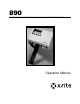
890 AUTOMATIC STRIP READING DENSITOMETER Operation Manual
Dear Customer: Congratulations! We at X-Rite, Incorporated are proud to present you with X-Rite 890 Auto Strip Reading, Color Photographic Densitometer. This instrument represents the very latest in microcontrollers, integrated circuits, optics, and display technology. As a result, your X-Rite instrument is a rugged and reliable instrument whose performance and design exhibit the qualities of a finely engineered instrument, which is not surpassed.
INTRODUCTION FCC This equipment has been tested and found to comply with the limits for a Class A digital device, pursuant to Part 15 of the FCC Rules. These limits are designed to provide reasonable protection against harmful interference when the equipment is operated in a commercial environment. This equipment generates, uses, and can radiate radio frequency energy and, if not installed and used in accordance with the instruction manual, may cause harmful interference to radio communications.
USER INFORMATION CE DECLARATION Manufacturer's Name: Manufacturer's Address: X-Rite, Incorporated 4300 44th Street, S.E. Grand Rapids, Michigan 49512 U.S.A. Model Name: Model No.: Densitometer 890 Directive(s) Conformance: EMC 89/336/EEC LVD 73/23/EEC WEEE As of August 13, 2005, X-Rite products meet the European Union – Waste Electrical and Electronic Equipment (WEEE) directive. Please refer to www.xrite.com for more information on X-Rite’s compliance with the WEEE directive.
INTRODUCTION LIMITED WARRANTY X-Rite, Incorporated (“X-Rite”) warrants each instrument manufactured to be free of defects in material and workmanship (excluding battery pack) for a period of 12 months. This warranty shall be fulfilled by the repair or replacement, at the option of X-Rite, of any part or parts, free of charge including labor, F.O.B. its factory or authorized service center.
TABLE OF CONTENTS This manual is organized into eight sections and four appendices. In order to make the best use of your instrument, it is recommended that you read all sections and appendices.
INTRODUCTION SECTION FOUR - Strip Operation Measuring Strips _________________________________________ 4-1 View Strip Data ___________________________________ 4-3 Manually Transmitting Strip Data____________________________ 4-5 SECTION FIVE - Service and General Maintenance Repair Information _______________________________________ 5-1 Cleaning the Instrument ___________________________________ 5-2 General Cleaning __________________________________ 5-2 Cleaning the Optics ________________________________
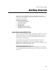
SECTION ONE Getting Started This section covers unpacking, inspection, and general set up of your instrument. Product description, paper guide adjustments, and measurement techniques are also include. Section One Contents • • • • • • Unpacking and Inspection Product Description Applying Power User Interface Adjusting the Paper Guides Strip Measurement Techniques UNPACKING AND INSPECTION After removing the instrument from the shipping carton, inspect for possible damage.
SECTION ONE PRODUCT DESCRIPTION The X-Rite 890 automated instruments measures paper, film, and printer balance control strips. Simply insert the strip into the instrument for motorized, automatic measurements. Red, green, and blue density data is sorted for fields such as HD, LD, and Stain, then simultaneously displayed and transmitted to a minilab printer for analysis. To accommodate the different size control strips, the instrument has adjustable paper guides on each side of the control strip entrance.
GETTING STARTED APPLYING POWER To apply power to the instrument: 1. Verify that the voltage indicated on the adapter complies with the AC line voltage in your area. If not, contact X-Rite or your authorized representative. 2. Insert the small plug from the adapter into the power-input connector on the instrument. 3. Plug the detachable line cord into the adapter. 4. Plug the line cord into an AC wall receptacle.
SECTION ONE USER INTERFACE The 890 instrument incorporates a three page menu system. Menu pages are displayed by continually pressing keyswitch l (p#) on the instrument. The first page contains all the predefined control strips. The last two pages provide access to the instrument setup options and strip measurement data. Main Menu • • • pap (paper) - accesses the paper measurement channel. The format selected remains selected until changed. film - access the film measurement channel.
GETTING STARTED Display and Keyswitch Definition The characters in the bottom row of the display dictate which function is selected or which action takes place when a corresponding keyswitch is pressed. Normally, upper-case lettering in the top row of the display is used for messages, and lower-case lettering in the bottom row is used for menu options that are selectable. Each keyswitch is embossed with identification marks signifying its number.
SECTION ONE ADJUSTING THE PAPER GUIDES To accommodate various size paper strips, the instrument has an adjustable paper guide on each side of the strip entrance. Each paper guide has a pointer (triangle) that is aligned with a number on the guide rail. The guide setting numbers are shown on the instrument display when a paper strip is selected. The paper guide rail has setting marks that range from “9-30” to the left and right of the center diamond.
GETTING STARTED STRIP MEASUREMENT TECHNIQUES All control strip types should have at least a 30.5mm (1.25”) leader before the first measurable patch. However, strips with less than a 30.5mm leader can also be measured reliably if required. Refer to your Control Strip and Balance Print Format Guide for leaderless strip measurement procedure. Supported strip definitions and strip insertion direction information is available in your Control Strip and Balance Print Format Guide shipped with your instrument.
SECTION ONE Single Pass Single pass strips require the strip to be inserted into the instrument once. In this example, the strip—Kodak RA4—can be inserted in either direction. Refer to your Control Strip and Balance Print Format Guide for information on all strips supported. 30 20 10 10 20 READ k:RA–4 ALL 18>other AT<18 30 Indicates ALL patches are measured Multi Pass Typically, a multi pass strip requires three pass through the instrument to obtain measurement data.
GETTING STARTED 20 20 10 10 PASS TWO 30 READ f:CP21 MAG 26>other AT<17 30 Indicates magenta patches are Guide number flashes, indicting strip positioning 20 20 10 10 PASS THREE 30 READ f:CP21 YEL 26>other AT<17 30 Indicates yellow patches are measured Guide number flashes, indicting strip positioning The third pass requires the strip to be rotated to take the measurement.
SECTION ONE Film Strip The Film category requires that the film strip be inserted into the 35mm slot located above the center diamond. In this example—Kodak C41—the strip can be inserted in either direction. Refer to your Control Strip and Balance Print Format Guide for information on all strips supported.
SECTION TWO Instrument Calibration This section covers the calibration procedures for your instrument. Section Two Contents • • • Calibration Information Auto Calibration Procedure Manual Calibration Procedure CALIBRATION INFORMATION The instrument has two types of calibration procedures available, automatic and manual. AUTO is the standard method of calibration. If you want your instrument to measure the same as another densitometer that has the same response, you would use the MANUAL procedure.
SECTION TWO AUTO CALIBRATION PROCEDURE NOTE: Make sure the Auto-Cal strip is free of dust, dirt, and smudgemarks. Refer to Section Eight for cleaning procedure. Handle cal strip by the edges. 1. Press key lll (cal) located on Function Menu page (p3) to initiate calibration. FUNCTION MENU p3 cnfg cal load • The instrument screen momentarily displays CALIBRATING TRANSMISSION during automatic transmission calibration (reading air), and CALIBRATING MOTOR SPEED.
INSTRUMENT CALIBRATION MANUAL CALIBRATION PROCEDURE The manual calibration procedure is used to correlate the low densities of the instrument to another densitometer. Doing this allows the instrument to measure approximately the same as another densitometer that has Status A reflection response, and has been calibrated to ANSI Standards. 1. Using the instrument's own reference, calibrate the densitometer that you want this instrument to correlate with. 2.
SECTION TWO 5. Enter the Red, Green, and Blue values you previously recorded into the designated fields. Press key llll (→) to move the cursor to the desired location, and to advance to the next step after editing the values. Press key ll (↑) to increase value and key lll (↓) to decrease value. RED GREEN BLUE Cursor 0.04 _ 0.07 0.08 → CAL R ↑ ↓ 6. INSERT CAL STRIP re-appears on the screen.
SECTION THREE Setting System Configuration The system configuration allows you to customize your instrument to meet your requirements. The configuration should be viewed and edited as needed before any measurements are taken. Section Three Contents • Instrument Configuration INSTRUMENT CONFIGURATION The configuration functions are contained in two main screen pages. Page one contains setup functions for instrument beeper tone, and network.
SECTION THREE Page 2 Configuration Options IO preset This options provides several QC system selections. All the necessary RS-232 interface parameters are automatically set when a predefined I/O preset is selected. A “CUSTOM” preset is available which allows you manually set all available I/O options. Below is a chart that contains all available I/O presets and their parameter settings. NOTE: Certain parameters are mandatory for the I/ O preset and cannot be changed.
SETTING SYSTEM CONFIGURATION XON When set to On (XON), this enables bi-directional transmit On/Off protocol. When set to Off (xon), the instrument ignores XON/OFF codes. Note, usage is limited to output at this point. Page 2b Configuration Options DPT (Decimal Point) Controls the decimal point availability during data output. When off (dtp), no decimal is output with data. When on (DTP), decimal points are included with the output data. COMP (Compact) Varies the output format of the data.
SECTION THREE • You can save and exit the configuration at anytime without editing all options. This is accomplished by simultaneously pressing key l and key ll when SAVE is displayed in the screen. • Configuration can be exited at anytime without saving changes by simultaneously pressing key lll and key llll (MENU keys). 1. Press key ll (cnfg) located on the Function Menu screen (p3) to enter Page1 Configuration screen. FUNCTION MENU p3 cnfg cal load 2.
SETTING SYSTEM CONFIGURATION 4. Page 2a Configuration Screen • Press key ll (RCI) to page through and select a remote control interface option (OFF, ON, TTL). • Press key lll (PIN5) to page through and select a handshake option (OFF, BUSY, and CTS). • Press key llll (XON) to select bi-directional transmit On/Off protocol option. Each key depression alternates between xon (off) and XON (on). • After editing Page 2a Configuration options, press key l (P2a) to advance to Page 2b Configuration screen.
SECTION THREE 7. Page 2d Configuration Screen • Press key ll (baud) to page through and select a baud rate option (300, 600, 1200, 2400, 4800, 9600, 19200, 38400, 57600). • Insert a piece of paper into the paper slot at least 1-¼” to activate the read switch—heavy paper or film works best. Press key llll (lock) to select lock option. Each key depression alternates between lock (off) and LOCK (on). A “LOCK” selection (padlock icon closed) prevents any option changes from occurring .
SECTION FOUR Strip Operation It is important to make sure control strips and reference strips used are from the same batch number. Always inspect control strips for damage before measuring. Care must also be taken when handing strips. Fingerprints on measurable patches can affect density values. IMPORTANT! When inserting strips into the instrument, there should be at least a 30.5mm (1.25”) leader before the outside edge of the first measurable target or the first target may not be detected.
SECTION FOUR 3. Measure strip • For paper strips, adjust the paper guides according to the number displayed on the screen. If multiple pass, note what color is to be measured first. Insert strip until it comes to rest against the drive rollers. • For film strips, note insertion direction and insert strip into the 35mm slot until it comes to rest against the drive rollers. • For printer balance strips, note insert direction and center bull’s-eye over middle diamond.
STRIP OPERATION View Strip Data Control strip data consists of the “actual” values measured by the instrument. Control strip data is viewed after a strip measurement or by selection from the Main Menu (p2). Viewing Data after Control Strip Measurement 1. Press key l (Stain) to page through RGB data fields of the strip. 2. After viewing data, press key llll (exit) to exit. Red Green Blue 0.29 0.34 0.54 Stain exit Viewing Control Strip Data from View Menu 1.
SECTION FOUR MANUALLY TRANSMITTING STRIP DATA The manual transmit function allows you to transmit data for the last measurement taken in the paper, film, and printer balance categories. 1. Press key lll (xmit) located on Main Menu page (p2) to enter Xmit Menu screen. MAIN MENU p2 view xmit 2. Press key ll (pap), key lll (film), or key llll (bal) to select strip category. XMIT MENU pap film bal NOTE: CHANNEL IS EMPTY appears in the display if no control strip data is available in the selected channel.
SECTION FIVE Service and General Maintenance This section covers repair information, cleaning, general maintenance, and troubleshooting tips for your instrument. Section Five Contents • • • • Repair Information Cleaning the Instrument Replacing the Read Lamp Troubleshooting Tips REPAIR INFORMATION The X-Rite 890 is covered by a one-year limited warranty and should be referred to the factory or an authorized service center for repairs within the warranty period.
SECTION FIVE CLEANING THE INSTRUMENT Your instrument requires very little maintenance to achieve years of reliable operation. However, to protect your investment and maintain reading accuracy, a few simple cleaning procedures should be performed from time to time. General Cleaning Whenever required, the exterior of the instrument may be wiped clean with a cloth dampened in water or a mild cleaner. NOTE: DO NOT use any ketone solvents to clean the unit, this will cause damage to the cover.
SERVICE AND GENERAL MAINTENANCE Cleaning the Calibration Strip (Part Number 880-100) The Auto-Cal strip can be cleaned with a mild soap detergent, and wiped dry with a clean, lint-free cloth. You must let the calibration strip dry completely before taking a calibration measurement. DO NOT clean below the bottom triangle. The attached label is not coated and smears when moisture is applied. DO NOT get fingerprints on any portion of the strip, handle by the edge.
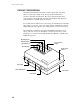
SECTION FIVE REPLACING THE READ LAMP (PART NUMBER 880-07) NOTICE: New lamp may appear bent, DO NOT attempt to straighten. 1. Remove four screws (2) securing the bottom cover (3) with a phillipshead screwdriver. Leave bottom cover (3) on unit. 2. Holding top (1) and bottom (3) covers in place, turn unit over so it rests on the bottom cover (3). Remove top cover (1). 3. Locate optics assembly (4) and remove screw and washer (5) in the middle of lamp assembly P.C.B. (6). 4.
SERVICE AND GENERAL MAINTENANCE TROUBLESHOOTING TIPS Reflection measurement incorrect: • Recalibrate instrument. • Clean reflection cal strip or replace if bad. • Replace read lamp.* • Contact X-Rite or Authorized Service Center. Transmission measurement incorrect: • Recalibrate instrument. • Replace read lamp.* • Contact X-Rite or Authorized Service Center. Transmission and Reflection measurement incorrect: • Recalibrate instrument. • Replace read lamp.
SECTION 5-6 FIVE
APPENDIX A Technical Specifications Transmission Process Control Film Width 35mm fixed slot or 1.4–6.0in. adjustable Measurement Speed 1.1 to 1.4 in./sec. (1.2 in./sec. typical) Spectral Response Status M Density Range 0–4.0D Density Accuracy ±.02D (0–3.0D), ±1% (3.1–3.4D) ±3% (3.5–4.0D) Density Repeatability ±.01D (0–3.0D) Control Strip Measurement Area 0.375” (length) x 0.5” (wide) minimum Reflection (paper) Process Control and Printer Balance Paper Width 1.4–6.0in.
APPENDIX A-2 A
APPENDIX B Error Messages Below is a list of typical error messages that can appear on your instrument’s display screen. If any error messages listed, or not listed should appear, make a note of it and take the appropriate steps to try to correct it. If an error message is consistently displayed, contact X-Rite or an authorized service center. Message Reason Possible Cause Solution INVALID READING PLEASE RE-READ! Unit did not recognize strip. Wrong strip selection. Select correct format.
APPENDIX B Message Reason Possible Cause UNRECOGNIZABLE AUTO-CAL STRIP! Unit did not feed consistently. Strip inserted in Insert strip correctly, Sec. 1. backwards or upsidedown. Cal strip is dirty. Clean cal strip, Sec. 8. Strip path is blocked by Clean strip path, Sec. 8. debris keeping cal strip from feeding properly. Motor drive roller Remove restraint/obstruction slippage due to restraint or dry drive rollers with air.
APPENDIX C Term Abbreviations ALF Automatic Line Feed ALL Strip is one pass and may be read in either direction (strip measurement mode) AXMT Automatic Transmit bal Printer Balance baud Varies unit of data transmission speed.
APPENDIX C Q.C.
APPENDIX D Parts List and Packaging Drawings Parts List D-1
APPENDIX D Packaging Drawing D-2
APPENDIX E 890 Instrument Firmware Update The instrument’s firmware is upgraded using Interface Cable P/N SE108-70 and DB Adapter P/N 881-71, both available from X-Rite. The following items are required to perform a 890 instrument firmware update: • • • • Computer with an available serial port 890 instrument with AC adapter Update firmware disk Interface cable (P/N SE108-70) and DB25 adapter (P/N 881-71) NOTE: Computer screen savers must be disabled during the update procedure.
APPENDIX E Step 2 Setting Instrument to Receive Update • Apply AC power to the instrument. NOTE: Make sure modem baud is set to "57.6K." To check baud, from P3 Function menu, press "Load" key, and then press "cfg" key. Next press "mod" key, and then press "baud" key. Adjust baud rate if required. • Enter the Load Menu by pressing key ll (netwk) on page 3 (p3) Function Menu. • Press key lll (load), Waiting for Host is displayed. Step 3 Firmware Update Procedure If you are running DOS under Windows 3.
Corporate Headquarters - USA 4300 44th Street SE Grand Rapids, Michigan 49512 Phone 1 800 248 9748 or 1 616 803 2100 Fax 1 800 292 4437 or 1 616 803 2705 Corporate Headquarters - Europe Althardstrasse 70 8105 Regensdorf Switzerland Phone (+41) 44 842 24 00 Fax (+41) 44 842 22 22 Corporate Headquarters - Asia Room 808-810 Kornhill Metro Tower, 1 Kornhill Road Quarry Bay, Hong Kong Phone (+852) 2 568 6283 Fax (+852) 2 885 8610 Please visit www.xrite.com for a local office near you. P/N 890-500 Rev.