WLAN 11g Broadband Router User Manual ver 1.
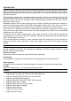
INFORMATION TO USER Product Name: X-Micro WLAN 11g Broadband Router Model Name: XWL-11GRAR FCC Radiation Exposure Statement This equipment complies with FCC radiation exposure limits set forth for an uncontrolled environment. This equipment should be installed and operated with minimum distance 20cm between the radiator & your body. This transmitter must not be co-located or operating in conjunction with any other antenna or transmitter.
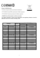
Europe - R&TTE Directive This device complies with the specifications listed below • ETS 300-826 General EMC requirements for Radio equipment. • ETS 300-328 Technical requirements for Radio equipment. • EN60950 SAFETY REQUIREMENTS FOR RADIO EQUIPMENT The channel identifiers, channel center frequencies, and regulatory domains of each 22MHz-wide channel are shown in following Table. COUNTRY CHANNELS MAX. OUT POWER INDOOR OUTDOOR Spain 2400-2483.
Copyright Copyright 2006 by X-Micro Technology Corp., All rights reserved. No part of this publication may be reproduced, transmitted, transcribed, stored in a retrieval system, or translated into any language or computer language, in any form or by any means, electronic, mechanical, magnetic, optical, chemical, manual or otherwise, without the prior written permission of X-Micro Technology Corp. Disclaimer X-Micro Technology Corp.
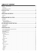
TABLE OF CONTENT ABOUT THIS GUIDE ............................................................................ 1 Purpose............................................................................................................................................................................... 1 Terms/Usage ...................................................................................................................................................................... 1 Overview of this User’s Guide ...
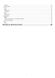
Dynamic ........................................................................................................................................................................ 33 Routing Table ................................................................................................................................................................ 34 Access ...................................................................................................................................................
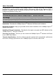
ABOUT THIS GUIDE Congratulations on your purchase of this 108Mbps Super-GTM Wireless LAN Router. This integrated access device combines Internet gateway functions with wireless LAN and Fast Ethernet switch. It provides a complete solution for Internet surfing and office resources sharing, and it is easy to configure and operate for every users. Purpose This manual discusses how to install the 108Mbps Super-GTM Wireless LAN Router.
INTRODUCTION With the explosive growth of the Internet, accessing information and services at any time, day or night has become a standard requirement for most people. The era of the standalone PC is waning. Networking technology is moving out of the exclusive domain of corporations and into homes with at least two computers. This integrated access device combines Internet gateway functions with wireless LAN and Fast Ethernet switch.
¾ ¾ ¾ ¾ ¾ Supports DNS Simple Firewall protection. Upgradeable firmware for future function. Simple setting using Setup Wizard. Easy configuration via WEB Browser.
UNPACKING AND SETUP This chapter provides unpacking and setup information for the 108Mbps Super-GTM Wireless LAN Router. Unpacking Open the box of the WLAN Router and carefully unpack it. The box should contain the following items: One 108Mbps Super-GTM Wireless LAN Router One dipole antenna One external power adapter One CD-ROM with this User’s Guide If any item is found missing or damaged, please contact your local reseller for replacement.
HARDWARE INSTALLATION Front Panel The figure below shows the front panel of the 108Mbps Super-GTM Wireless LAN Router. Front Panel Power This indicator lights green when the hub is receives power, otherwise it is off. Status This indicator blinking green means the WLAN Router is working successful. Otherwise, this indicator always on or off means the function of the WLAN Router is fail. WAN (Link/ACT) The indicators light green when the WAN port was connected to an xDSL/Cable modem successfully.
Rear Panel The figure below shows the rear panel of the 108Mbps Super-GTM Wireless LAN Router. Rear Panel Antenna There is one 2dBi Gain Antenna in the rear panel for wireless connection. LAN (1-4) Four RJ-45 10/100Mbps Auto-MDIX ports for connecting to either 10Mbps or 100Mbps Ethernet connections. WAN In the four port broadband router, there is an RJ-45 10/100Mbps Auto-MDIX port for the WAN that will fit the xDSL/Cable modem’s specification need.
Hardware connections Connecting the WLAN Router 1. Plug in one end of the network cable to the WAN port of the WLAN Router. 2. Plug in the other end of the network cable to the Ethernet port of the xDSL or Cable modem. 3. Use another network cable to connect to the Ethernet card on the computer system; the other end of the cable connects to the LAN port of the WLAN Router. Since the 108Mbps Super-GTM Wireless LAN Router has four ports, you can connect up to four computers directly to the unit.
PC NETWORK TCP/IP SETTING The network TCP/IP settings differ based (Win95/98/ME/NT/2000/XP) and are as follows. on the computer’s Windows 95/98/ME 1. 2. 3. 4. Click on the “Network neighborhood” icon found on the desktop. Click the right mouse button and a context menu will be show. Select “Properties” to enter the TCP/IP setting screen. Select “Obtain an IP address automatically” on the “IP address” field. 5. Select “Disable DNS” in the “DNS” field. 6. Select “None” for the “Gateway address” field.
Windows 2000 Double click on the “My computer” icon on the desktop. When “My computer” window opens, open the “Control panel” and then open the “Network dialup connection” applet. Double click on the “Local area network connection” icon. Select “Properties” to enter the TCP/IP setting window. 1. In the “Local area network status” window, click on “Properties.” 2. In the “Local area network connection” window, first select TCP/IP setting and then select “Properties.” 3.
10
CONFIGURATION First make sure that the network connections are functioning normally. This WLAN Router can be configured using Internet Explorer 5.0 or newer web browser versions. Login to the WLAN Router through Wireless LAN Before configuring the WLAN Router through WLAN, make sure that the SSID, Channel and the WEP is set properly.
Step 1: Set up new Password User can change the password and then click “Next” to continue.
Step 2: Choose time zone Select the time zone from the drop down list. Please click “Next” to continue. Step 3: Set LAN connection and DHCP server Set user’s IP address and mask. The default IP is 192.168.1.1. If user likes to enable DHCP, please click “Enabled”. DHCP enabled is able to automatically assign IP addresses. Please assign the range of IP addresses in the fields of “Range start” and “Range end”. Please click “Next” to continue.
Step 4: Set Internet connection Select how the router will set up the Internet connection: Obtained IP automatically; Fixed IP address; PPPoE to obtain IP automatically; PPPoE with a fixed IP address; PPTP. Obtain IP automatically (DHCP client): If user has enabled DHCP server, choose "Obtain IP automatically (DHCP client)" to have the WLAN Router assign IP addresses automatically.
Fixed IP Address: If the Internet Service Providers assign a fixed IP address, choose this option and enter the assigned IP address, subnet mask, gateway IP and DNS IP addresses for the WLAN Router.
PPPoE to obtain IP automatically: If connected to the Internet using a PPPoE (Dial-up xDSL) Modem, the ISP will provide a Password and User Name, and then the ISP uses PPPoE. Choose this option and enter the required information.
PPPoE with a fixed IP address: If connected to the Internet using a PPPoE (Dial-up xDSL) Modem, the ISP will provide a Password, User Name and a Fixed IP Address, choose this option and enter the required information.
PPTP: If connected to the Internet using a (PPTP) xDSL Modem, enter the your IP Address, Subnet Mask, Gateway, Server IP, PPTP Account and PPTP Password, Your Subnet Mask required by your ISP in the appropriate fields. If your ISP has provided you with a Connection ID, enter it in the Connection ID field, otherwise, leave it zero.
L2TP: If connected to the Internet using a L2TP (Dial-up xDSL) Modem, the ISP will provide a Server IP. Account and Password. Choose this option and enter the required information.
Step 5: Set Wireless LAN connection Click “Enable” to enable wireless LAN. If user enables the wireless LAN, type the SSID in the text box and select a communications channel. The SSID and channel must be the same as wireless devices attempting communication to the router. Step 6: Setup completed The Setup wizard is now completed. The new settings will be effective after the Wireless router restarted. Please click “Restart” to reboot the router.
Advanced configuration LAN Setting The screen enables user to configure the LAN & DHCP Server, set WAN parameters, create Administrator and User passwords, and set the local time, time zone, and dynamic DNS. LAN & DHCP Server This page leads to set LAN and DHCP properties, such as the host name, IP address, subnet mask, and domain name. LAN and DHCP profiles are listed in the DHCP table at the bottom of the screen. Host Name: Type the host name in the text box. The host name is required by some ISPs.
Connection Type: Select the connection type, either DHCP client, Fixed IP, PPPoE, PPTP or L2TP from the drop-down list. WAN IP: Select whether user wants to specify an IP address manually, or want DHCP to obtain an IP address automatically. When Specify IP is selected, type the IP address, subnet mask, and default gateway in the text boxes. User’s ISP will provide with this information. DNS 1/2/3: Type up to three DNS numbers in the text boxes. User’s ISP will provide with this information.
Password This screen enables user to set administrative and user passwords. These passwords are used to gain access to the router interface. Administrator: Type the password the Administrator will use to log in to the system. The password must be typed again for confirmation. The authority if Administrator allow user configuration of the WLAN Router. User: Type the password the User will use to log in to the system. The password must be typed again for confirmation.
Local Time: Displays the local time and date. Time Zone: Select the time zone from the drop-down list. Synchronize the clock with: Select the clock adjustment method form the drop-down list. Automatic: Automatically adjust the system time from NTP Server. Manual: Manually adjust the system time when you press the Set Time button. Default NTP server: The Simple Network Time Protocol (SNTP) server allows the WLAN Router to synchronize the system clock to the global Internet through the SNTP Server.
Wireless This section enables user to configuration the wireless communications parameters for the WLAN Router. Basic This page allow user to enable and disable the wireless LAN function, create a SSID, and select the channel for wireless communications. Enable/Disable: Enables and disables wireless LAN via the WLAN Router. SSID: Type an SSID in the text box. The SSID of any wireless device must match the SSID typed here in order for the wireless device to access the LAN and WAN via the router.
Authentication The authentication type default is set to disable. There are four options: Disable, WEP, WPA, and WPA2. Authentication Type: The authentication type default is set to open system. There are three options: Open System; Shared Key, WPA and WPA-PKS. WEP Encryption WEP: Open System allows public access to the router via wireless communications; Shared Key requires the user to set a WEP key to exchange data with other wireless clients that have the same WEP key..
If WPA or WPA2 is selected, the below screen is shown. Please set the length of the encryption key and the parameters for the RADIUS server. Lifetime: Select the Lifetime of the Encryption Key from 5 Minutes to 1 Day. As soon as the lifetime of the Encryption Key is over, the Encryption Key will be renewed by the Radius server. Encryption Key: Select the Encryption Key Length Size ranging from 64 to 128 Bits that you would like to use. RADIUS Server: 1.
Advanced This screen enables user to configure advanced wireless functions. Beacon Interval: Type the beacon interval in the text box. User can specify a value from 1 to 1000. The default beacon interval is 100. RTS Threshold: Type the RTS (Request-To-Send) threshold in the text box. This value stabilizes data flow. If data flow is irregular, choose values between 256 and 2346 until data flow is normalized. Fragmentation Threshold: Type the fragmentation threshold in the text box.
Status This selection enables user to view the status of the router LAN, WAN and Wireless connections, and view logs and statistics pertaining to connections and packet transfers. Device Information This screen enables user to view the router LAN, Wireless and WAN configuration. Firmware Version: Displays the latest build of the router firmware interface. After updating the firmware in Tools - Firmware, check this to ensure that the firmware was successfully updated.
Click “Last Page” to view the final page of the log Click “Previous Page” to view the page just before the current page Click “Next Page” to view the page just after the current page Click “Clear Log” to delete the contents of the log and begin a new log Click “Refresh” to renew log statistics Time: Displays the time and date that the log entry was created. Message: Displays summary information about the log entry. Source: Displays the source of the communication.
Log Setting This screen enables user to set router logging parameters. SMTP Server: Type the SMTP server address for the email that the log will be sent to in the next field. Send to: Type an email address for the log to be sent to. Click “Email Log Now” to immediately send the current log. Syslog Server: Type the IP address of the Syslog Server if user wants the router to listen and receive incoming Syslog messages.
Statistic This screen displays a table that shows the rate of packet transmission via the router LAN, Wireless and WAN ports (in bytes per second). Click “Reset” to erase all statistics and begin logging statistics again. Wireless This screen enables user to view information about wireless devices that are connected to the WLAN Router. Connected Time: Displays how long the wireless device has been connected to the LAN via the router. MAC Address: Displays the devices wireless LAN interface MAC address.
Routing This selection enables user to set how the router forwards data: Static and Dynamic. Routing Table enables user to view the information created by the router that displays the network interconnection topology. Static It enables user to set parameters by which the router forwards data to its destination if user’s network has a static IP address. Network Address: Type the static IP address user’s network uses to access the Internet.
NAT: Click the radio buttons to enable or disable the NAT function. Transmit: Click the radio buttons to set the desired transmit parameters, disabled, RIP 1, or RIP 2. Receive: Click the radio buttons to set the desired transmit parameters, disabled, RIP 1, or RIP 2. Routing Table This screen enables user to view the routing table for the router. The routing table is a database created by the router that displays the network interconnection topology.
35
MAC Filters MAC Filter: Enables you to allow or deny Internet access to users within the LAN based upon the MAC address of their network interface. Click the radio button next to Disabled to disable the MAC filter. Disable: Disable the MAC filter function. Allow: Only allow computers with MAC address listed in the MAC Table. Deny: All users are allowed Internet access except those computers in the MAC Table are deny Internet access.
Enable / Disable: Enable or Disable the URL blocking function of the WLAN Router. Add: Add the specific URL to the URL blocking list. Delete: Selected a URL from the blocking list then click the Delete button to remove the URL from the URL Blocking list.
IP Filters This screen enables you to define a minimum and maximum IP address range filter; all IP addresses falling in the range are not allowed Internet access. The IP filter profiles are listed in the table at the bottom of the page. (Note: Click anywhere in the item. Once the line is selected, the fields automatically load the item's parameters, which you can edit.) Enable: Click to enable or disable the IP address filter. Range Start: Type the minimum address for the IP range.
Domain Blocking You could specify the domains that allow users to access or deny by clicking one of the two items. Also, add the specified domains in the text box. Disable: Disable the Domain Blocking function. Allow: Allow users to access all domains except “Blocking Domains”. Deny: Deny users to access all domains except “Permitted Domains”. Blocked/Permitted Domains: List domains you will Blocked or Permotted. Add: Click to Add button to add domain to the Blocked/Permitted Domains list.
Protocol Filters This screen enables you to allow and deny access based upon a communications protocol list you create. The protocol filter profiles are listed in the table at the bottom of the page. Note: When selecting items in the table at the bottom, click anywhere in the item. The line is selected, and the fields automatically load the item's parameters, which you can edit. Enable: Click to enable or disable the Protocol filter. Name: Type the name of the user to be denied access.
Virtual Server This screen enables user to create a virtual server via the router. If the router is set as a virtual server, remote users requesting Web or FTP services through the WAN are directed to local servers in the LAN. The router redirects the request via the protocol and port numbers to the correct LAN server. The Virtual Sever profiles are listed in the table at the bottom of the page. Note: When selecting items in the table at the bottom, click anywhere in the item.
Special AP This screen enables user to specify special applications, such as games, that require multiple connections that are inhibited by NAT. The special applications profiles are listed in the table at the bottom of the page. Note: When selecting items in the table at the bottom, click anywhere in the item. The line is selected, and the fields automatically load the item's parameters, which user can edit. Enable: Click to enable or disable the application profile.
Trigger: Defines the outgoing communication that determines whether the user has legitimate access to the application. ● Protocol: Select the protocol (TCP, UDP, or ICMP) that can be used to access the application. ● Port Range: Type the port range that can be used to access the application in the text boxes. ● Incoming: Defines which incoming communications users are permitted to connect with. ● Protocol: Select the protocol (TCP, UDP, or ICMP) that can be used by the incoming communication.
Enable: Click to enable or disable the firewall rule profile. Name: Type a descriptive name for the firewall rule profile. Action: Select whether to allow or deny packets that conform to the rule. Source: Defines the source of the incoming packet that the rule is applied to. ● Interface: Select which interface (WAN or LAN) the rule is applied to. ● IP Range Start: Type the start IP address that the rule is applied to. ● IP Range End: Type the end IP address that the rule is applied to.
SNMP This screen enables you to configure the SNMP. Enabled/Disabled: Click to enable or disable SNMP. System Name: A name given to the router. System Location: Description the location of the router (normally, the DNS name). System Contact: Description the contact information for the person responsible for the router. Community: SNMP system name for exchanging SNMP community messages. The name can be used to limit SNMP messages passing through the network. The default name is 'public.
Allow to Ping WAN Port: Type a range of router IP addresses that can be pinged from remote locations UPNP Enable: UPNP is short for Universal Plug and Play that is a networking architecture that provides compatibility among networking equipment, software, and peripherals. The Router is an UPnP enabled router and will only work with other UPnP devices/software. If user does not want to use the UPnP functionality, selecting “Disabled” can disable it.
Tools This page enables user to restart the system, save and load different settings as profiles, restore factory default settings, run a setup wizard to configure router settings, upgrade the firmware, and ping remote IP addresses. Reset Click “Restart” to restart the system in the event the system is not performing correctly. Settings This screen enables user to save settings as a profile and load profiles for different circumstances.
Please follow the below instructions: Download the latest firmware from the manufacturer's Web site, and save it to disk. Click “Browse” and go to the location of the downloaded firmware file. Select the file and click “Upgrade” to update the firmware to the latest release. Ping Test The ping test enables user to determine whether an IP address or host is present on the Internet. Type the host name or IP address in the text box and click Ping.
TECHNICAL SPECIFICATIONS General Standards Protocol Radio Technology Data Transfer Rate Topology Receiver Sensitivity TX Power Network Cables Frequency Range Modulation Schemes Security Channels Number of Ports IEEE 802.3u 100BASE-TX Fast Ethernet IEEE 802.11g; IEEE 802.11b CSMA/CD IEEE 802.11g Orthogonal Frequency Division Modulation 802.11b: 1, 2, 5.5, 11Mbps (auto sense) 802.
www.x-micro.