X – 6 CUBED K 030 CONVERSION KIT INSTRUCTION MANUAL Version 1.0 X – 6 CUBED K 030 X – 6 Cubed Instruction Manual v1.
TABLE OF CONTENTS B 4.2 Disassembly……………………………………………………….... 6 Bag A – Transmission Assembly………………..……………………….. 11 Bag B – Nose Piece………………………………………………………... 21 Bag C – Shock Tower ……………………………………………………… 24 Bag D – Transmission Installation…….…………………………………... 26 Bag E – Rear Suspension ……………………………………. 30 Bag F – Finish It up………………………………………………………… 34 Parts List…………………………………………………………………….. 39 Race Prep…………………………………………………………………….. 40 Tuning Section………………………………………………………………...
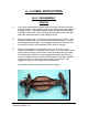
X – 6 CUBED ASSEMBLY INSTRUCTIONS FIRST THINGS FIRST A) ASSUMPTIONS These instructions assume several things: 1. You have at least some experience building R/C cars. These instructions are not written for a first-timer. 2. You have the usual assortment of R/C tools. 3. You have a Team Associated B 4, 4.1, or 4.2 rolling chassis.. If you do not meet all the assumptions above, please contact us immediately. Contact information is on Page 5.
CARE AND FEEDING OF CARBON FIBER Throughout your Kit we have deliberately cut the bolt holes in the CF parts on the small side for a good tight fit. Thread them up through and then give an extra twist or two so they will be snug but free. Carbon fiber is a laminate, much like plywood, and is produced similar to laying up fiberglass. While the material is extremely strong and light, without proper attention it can begin to delaminate, leaving a “frayed” appearance around the edges.
SOME IMPORTANT INFORMATION We are not perfect. If you experience the slightest difficulty assembling your X – 6 Cubed, either because a part does not fit properly or because you have difficulty with the instructions, please contact us immediately. Even if you figure out what needs to be done, or make a modification that allows the part to fit, we want to make changes that help the next person. You are much more than a customer at X Factory.
X – 6 CUBED INSTRUCTIONS B 4.2 DISASSEMBLY GENERAL 1) You are too experienced to require photos for these first few instructions. Remove the body. We suggest you store the clips by putting them back in the body mounts. Remove the wheels. Again, store the nuts by putting them back on the axles. We store things this way often so they are right where we need them when we are looking for them. 2) Remove the gear cover. You will not need this part or the screws.
4) From beneath the chassis, remove the two flat head screws which hold the bumper to the chassis & bulkhead. Save the bumper and screws for re-use. 5) Still working beneath the chassis, remove the two flat head screws which hold the bulkhead to the chassis. Save these screws for re-use. 6) From the top, remove the three screws and washers that hold the top plate to the chassis. Save the screws for re-use. 7) Carefully remove the front suspension and steering assembly and set it aside for re-use.
C.V.D.S & HUB CARRIERS 8) Remove the rear shock assemblies. From each side, take out the bottom bolt, then remove the plastic nut from the top. Save shocks and their bolts & nuts. Don’t lose the aluminum bushing in the bottom shock eyelet! Now remove the upper mounting bolts and bushings. Save everything for reuse. 9) Twist the camber link inner ball cups off their ball studs, then remove the ball studs.
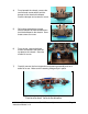
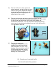
TRANSMISSION 11) Remove the gear cover. Two flat head screws from the bottom and two button heads from the top. Save the flat head screws for Inst. # E14 and the button heads for # F7. 12) Remove the two 5/8” flat head screws that hold the wing mounts to the shock tower and save the screws for Inst. # B1. 13) Remove the long bolt that holds the wing mounts to the transmission. This bolt will not be used. Remove the left wing mount. 14) Remove the two bolts holding the transmission in the car.
15) Remove the 5-40 nut which secures the slipper assembly, and pull off the nut, spring retainer, spring, outer slipper plate, slipper housing assembly with pads, spur gear, inner slipper pad, and inner slipper plate. All slipper parts will be re-used. 16) Remove the three long cap head screws (long arrows) from the transmission and take off the motor plate and wing mount. Then remove the last shorter cap head screw (short arrow), and separate the transmission case halves.
BAG A TRANSMISSION BALL DIFFERENTIAL The B 4.2 and 4.1 diff uses metric outdrives and the X Factory 4-Gear transmission uses U.S. measurement, so we’ll re-build the whole thing now. If your donor truck is a B4, you have the U.S. sized outdrives & bearings. They fit the 4-Gear. A1) Hold the outdrive with the T-nut (AE6575) in one hand and insert the Allen driver through the white protector cap (AE6575) and into the head of the diff thrust bolt (AE6573). Unscrew the bolt.
A4) Check your diff rings for wear. If they’re not new, there will be a thin line on the face of each one where the balls run. Darker line = more wear. You can use both sides of the rings, so if one side has not been used, flip them over. Carbide diff balls like X Factory’s #6500 are much harder than the rings, so one set of balls should last through several sets of rings. Many X Factory drivers prefer B Fast diff rings for smoother, longer-lasting diffs.
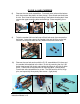
A7) Install the spring and T-nut into the male outdrive. Be certain the lugs on the T-nut engage properly in the slots of the outdrive. Set aside until A10. A8) Check the thrust washers for wear. They wear just as the diff rings do, and are also reversible. Stand the diff bolt up on end and install one washer on it with a new side up (left photo). Put some thrust grease all around the exposed surface of the washer and place the six thrust balls on the washer (center photo).
A10) Now slide the male outdrive from step A7 into the female outdrive assembly from step A9. Slide the diff bolt through the male outdrive and screw it into the T-nut. Do not tighten very much yet. See A11 below. A11) As the bolt begins to tighten, stop every revolution or two, remove the wrench, and rotate the two outdrives at the same time in opposite directions while pushing them together (left photo). This helps seat the balls, rings, and thrust bearing while it distributes the grease.
ASSEMBLE THE X – 6 Cubed TRANSMISSION A13) Remove the transmission case (XF5001) from Bag A and separate the two halves. Note the small round ejector pin bosses on the mounting tabs. You may wish to file these flat for ease of installation in the truck. A14) Install a saved 3/16” X 3/8” rubber sealed bearing (XF6200) all the way into the top shaft boss in the left transmission case half (short arrow) and a 3/8” X 5/8” (XF6203) bearing from Bag A in the boss for the differential (long arrow).
A16) Gather together the idler gear from the B 4.2 (AE9360) along with its 3/16” X 3/8” bearings (XF6202) and shaft (XF5201) along with the same parts from bag A so you have two gears, two shafts, and four bearings. Install a bearing into each side of both idler gears. Team drivers do it by pushing on the outer race with a socket. A17) Slide an idler shaft through the bearings in each idler gear, then place the shafts in their bosses in the left transmission half.
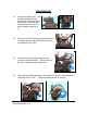
transmission should be free and smooth. A19) Install the remaining 3/16” X 3/8” rubber seal bearing and 3/8” X 5/8” bearing into their bosses in the right transmission case half. (long arrows) There is a small hole in the case where the top shaft bearing goes so you can use a hex wrench to push out the bearing. Some drivers like to run a small bead of inexpensive grease around the mating surface of the right transmission case half.
A21) Install the 4-40 X 3/8” cap head bolt (XF6001) in the lower corner of the trans case, just finger tight for now to hold things together. A22) The X Factory 4-Gear motor plate (XF1234) has four “extra” holes. Two of them (left photo, short arrows) are used to install the optional #5050 heatsink and fan. Two more may be used later if we make a gear cover (center photo, short arrows). Long arrows in the right photo point to the three holes that attach the motor plate to the transmission.
SLIPPER INSTALLATION A24) Install a slipper plate (XF5530) onto the top shaft, flat side out. The flats inside the plate will key to the flats on the shaft. A25) Put the inner slipper pad (AE9603) on the spur gear (AE9651) (left & center photos). The hex of the pad fits into the molded hex in the gear. Now turn the transmission so the top shaft with slipper plate is facing down.
A27) Install the spring (AE9739) on the shaft so it fits into the slipper plate’s hub, then place the black retainer (AE7486) over the spring, flat side up. Install the 5-40 nut (XF6074) to hold it all together, tightening until there is one thread of the shaft showing. Final adjustment later. That’s it for the hardest, longest bag. All downhill from here! Set the trans aside and we’ll do the front end. K 030 X – 6 Cubed Instruction Manual v1.
BAG B NOSE PIECE B1) Place a 5/8” flat head screw (XF 6024) you saved from inst. # 12 up from the bottom of the chassis in the second hole from the front at the outside of right side of the chassis (short arrow). Place a 7/8” flat head screw (XF 6026) from Bag B up through the front outside hole (long arrow). B2) Place a Nose Bridge Spacer (XF 1534) over the two bolts. B3) Place a Nose Bridge (XF 1533) over the screws onto the spacer, curved side out.
B5) Now repeat the first four steps for the left side. B6) Let’s do both sides together now. Put the Lower Nose Bridge Stiffeners (XF 1535) over the 7/8” flat heads. They should fit snugly against the top deck support (short arrow). B7) Guess what? Now the Top Nose Bridge Stiffeners (XF 1536) Again, nice and snug against the top deck support (short arrow). Both sides, please, even though the photo only shows one.
B10) Back to the top. Put the 13/32” Stand-Offs (XF 6803) on the two front screws (long arrows). They should snuggle up with the top stiffener (short arrow). If you are using thread lock, put a drop in the stand-off here. Hold them with a pliers and tighten from the bottom. Team drivers put a cloth between the stand-off and the pliers to keep the stand-off nice and shiny. Secure the other four screws with locking nuts (XF 6071).
BAG C REAR SHOCK TOWER C1) Install the wing mounts first. You will need the Rear Shock Tower (XF3315), Wing Mounts (XF 3500), and Wing Mount Spacers (XF 6806). C2) Place two 4-40 X 5/8” cap head screws (long arrows) through the left wing mount holes. There are two sets of holes; here we are using the lower set. Consult the Set-Up Sheet and Tuning Section to determine which you want. Then put two Wing Mount Spacers over the bolts (short arrows). C3) Install the one wing mount, then the other.
C5) Place the Ball Stud Lands (XF 3800) on the shock tower, then install finger tight with the 5/8” flat head screws (XF 6024) If you use thread lock, put a drop now in the lower tapped holes of the ball stud lands to prepare for inst. C6.. C6) Turn the bulkhead over and install the two 5/8” cap head screws (XF 6004) with flat washers (XF 6080). Now tighten the flat heads from C5. C7) Check the Set-Up Sheet and Tuning Section. Install the two ball studs you saved with any washers.
BAG D TRANSMISSION INSTALLATION D1) Place two 3/8” flat head screws (XF 6022) up from under the chassis, put the 2mm Hinge Pin Brace Spacer (XF 3262) over the screws, and install the Hinge Pin Brace (XF 3260) with the bushing holes (arrows) facing back. D2) Place two 3/8” flat head screws (short arrows) up from under the chassis for the front of the transmission cradle and two 1” flat head screws (XF 6027, long arrows) for the back of the cradle D3) Install the transmission cradle (XF5030).
D4) Place two 3/8” flat head screws up from under the chassis for the Motor plate support bracket. Put one 0.030” spacer (XF 3250) on each screw, and install the motor plate support bracket (XF 1130). Leave these screws finger tight for now. Note that the bracket is off-set to the left. D5) Place the bulkhead and shock tower assembly into the rear of the transmission cradle and secure with the 1/2” cap head you saved from inst # 16 (long arrow).
D8) Place a transmission shim over each of the 1” bolts that come up through the bulkhead. For this photo we have used 0.060” shims so they show well. This is strictly for purposes of clarity. It is important that all four shims be the same size on your X – 6 Cubed! D9) Place the other two T\transmission shims over the front bosses of the transmission cradle. In this photo we have used the 0.030” shims for clarity.
D12) Put a washer over the other 4-40 X 3/8” bolt and secure the right front of the transmission. Make sure the shim is still in there! Make this bolt finger tight for now. D13) One last check now to be sure the correct shims stayed under the transmission at the rear, then put #4 flat washers over the 1” bolts (left photo) and secure with the #4 mini nuts (right photo).
BAG E REAR SUSPENSION E1) Take the rear control arms (XF3012) from Bag E and remove the gurfelmurgles (arrows). Many drivers touch the arms with a file here. E2) We’ll do the right side first. Take the C.V.A. out of the hub. The bearings can stay in the hub, though we suggest you clean and inspect them now. Team drivers install the X Factory CF Hub Camber Plates (XF 9502) now. They use the lowered plates in many set-ups. E3) We will add two 0.
E5) Again, the right side first. Insert a hinge pin you saved into a control arm from the rear. Consult the Set-Up Sheet and Tuning section to determine your hub spacing. Here we have the two shims on the rear for hubs forward. The shock mounting holes are on the rear of the arm. E6) Place the right hub (Marked R) on the hinge pin and continue sliding the pin forward. The two shims have remained behind the hub (arrows). E7) Secure the hinge pin with the little 256 X 1/8” button head screw.
E9) Install the hinge pins (XF 6141) in the bushings. E10) Check the Set-Up Sheet and Tuning Section to determine how you will space your control arms on the hinge pin. Slide at least one thin shim over the hinge pin to prevent friction between the control arm and hinge pin brace. Here we have used two dialed Real Men Wear Black 0.030” shims. E11) Place the two control arms on the hinge pins. Shock holes to the rear! E12) Two Toe-In Bars (XF 3211) are in Bag E, marked 3 and 4.
E14) Place the shims under the toe-in bar and secure with two 4-40 X 1/2” flat head screws saved from inst # 11. The photos show one of each shim, or 0.090”. E15) Using the hardware you saved from the rear shocks, install the upper shock mounting bolt in the tower. Check the Set-Up Sheet and Tuning Section to determine how your shocks will be mounted. Here we are using the #2 hole. If you have Big Bore shocks, install a 0.060” spacer (XF 5702).
BAG F FINISH IT UP F1) Place two 3/8” flat head screws up through the two holes at the right rear corner of the chassis. F2) Remove the bag of Chassis Shims (XF 1012) from Bag F and place one of the medium-size shims over the two bolts from F1 above. Then bolt on a Rear Top Deck Support (XF 1311). If you use thread lock, a drop in each hole of the top deck support. Repeat for the left side.
F5) Place four 4-40 X 3/8” flat head screws up through the chassis, one at each corner of the battery compartment, and put a 0.060” shim on each bolt. F6) Install the four 7/8” Stand-Offs (XF 6802). If you are into thread lock, a drop in each one. F7) Find the two button head screws you saved from inst. 11 and the two 4-40 X 1/4 button head screws (XF 6041) from Bag F. Install the four 0.156” Hex Stand-Offs (XF 6805) in the slots of the battery strap (XF 1229). Finger tight for now.
F9) SADDLE PACK Use the battery spacer foam (AE 9238) from your B 4.2 between the two saddle batteries to space them out to the edge of the battery compartment. For pack forward (left photo) use only the rear two hex stand-offs, adjusting them to hold the battery tight against the front of the battery compartment. For pack back (right photo), use the front two hexes. SHORTY PACK Here you have more choice of placement. The pack can go anywhere in the battery compartment.
F11) We are showing you the top deck here because it makes sense to us this way, but you may want to install the electronics before the top deck. Place the smallest two chassis shims on the front top deck supports (left photo) and place the top deck over its supports. Use seven 4-40 X 3/8” cap head screws for the front deck supports and center posts. F12 Place a 4-40 X 3/8” Button Head screw through each dialed carbon fiber (!) Body Mount (XF 6321), then attach the rear of the top deck.
F14) If your servo is wide, it may foul the corners of the nose piece. Not to worry, just use a file or a rotary tool to remove about 1/8” of material from raised corner of the nose piece where indicated. We have been doing this for several years and there is lots of material here, so you won’t weaken it. Only the left side has been done in this photo so you can see the difference. F15) Install the antenna tube into its mount by pushing it through from the top.
PARTS LIST PART # DESCRIPTION 1002 1012 1013 1130 1229 1234 1311 1313 1400 1503 1533 1534 1535 1536 3012 3211 3250 3260 3262 3315 3500 3800 5001 5030 5201 5702 6001 6003 6004 6022 6023 6024 6026 6027 6041 6042 6043 6071 6073 6080 6141 6142 6202 6203 6321 6450 6801 6802 6803 6805 6806 8024 8243 9001 Nose Piece Chassis Spacers, CF Chassis, CF, X – 6 Cubed Motor Plate Support Bracket Battery Strap, CF, X – 6 Cubed Motor Plate, Lowered Top Deck Support, Rear Bulkhead, Rear, Tower Forward Top Deck Support, Fr
FINAL SET-UP AND PREP ELECTRONICS Now that the car is built and electronics installed, it’s time to make certain it runs straight and well. First, familiarize yourself with the set-up procedures of your various electronics: how to bind the receiver to the radio transmitter, how to set the speed controller to the radio, and how to adjust the steering settings on your transmitter.
BREAK IN THE DIFF We’re ready to run now, right? Not Quite. The next thing to do is break in the differential. This is exceedingly important to the car’s performance and diff life. With the car all prepped as above, install a charged battery and put the car back on its stand with the rear wheels off the ground. Turn on the transmitter and car, then adjust the trim on the throttle so that, with no throttle input, the motor begins running at a slow constant speed.
RACE PREPARATION The 5 Ps: Proper Preparation Prevents Poor Performance. You want a well-built car when you arrive at the track, but top drivers also have a routine before every run to make sure the car’s settings are consistent each time out. This makes sure the car on the track is indeed what you want, and any performance difference is the result of deliberate changes. Here is a list of things we check each time the car hits the track, for practice or racing.
TUNING SECTION ABOUT ADJUSTMENTS R/C race cars, in general, are some of the most adjustable racing machines of any scale. What’s really amazing is just how easy and quick it is to make all of our changes: remove a ball stud to change roll center, one screw to change springs, or tape in some weight to change the car’s distribution.
racing lines, while the rear end stays more planted. Watch out that you don’t slam into the motor guards of other cars through the infield! The initial disadvantage of the mid-motor concept was a lack of forward bite out of corners, especially on slick tracks. X Factory designed the 4-gear transmission to solve this problem: by turning the motor so it rotates in the same direction as the wheels, the motor itself helps transfer weight to the rear under acceleration, dramatically increasing forward bite.
slipper accordingly. On super high-bite surfaces, you’ll actually back the slipper off some to prevent the car from pulling hard wheelies. The nice thing about slippers is the ease of adjustment: have a friend take a ¼” wrench out to the track, and a few brief pit stops later you can have the car completely dialed.
anti-squat; with approximately 0.120” (3 mm) of rear spacing the car has 0o, so every .030” (.74 mm) of spacers is a degree less. The thin white nylon shims included in the kit are .030”; the thicker ones are .060”. More anti-squat (rear of pins down) will generally take away rear side bite, add forward bite, and let the car spring more off jumps, generating a higher arc in the air. A car with more anti-squat will ‘rotate’ easier in sharp corners.
TRANSMISSION HEIGHT The X – 6 Cubed features X Factory’s adjustable-height transmission. While not the easiest adjustment, it’s a very powerful tuning tool to adapt the car to different surfaces. Included in Bag D (step D7) are several sets of transmission shims, four each of .030”, .060”, and .090”. Counting zero, that’s four transmission height positions. When you change transmission height, make sure to re-check rear ride-height (remember the race preparation list?).
The rear tires are always run with toe-in, but the amount can be changed. It is adjusted by switching the rear tor-in block (installed in step E12). More rear toe-in (the 4o block) gives the car more forward traction but makes it harder to pivot the car. Less rear toe-in (the 3o block) will let the car flow through corners and pivot well, but at a loss of stability off the line and out of corners. A drag car would use lots of rear toe-in.
flat front-to-rear, or perhaps a touch higher in the back. Lowering one end of the car will give that end a little more grip, but extreme differences can make it more difficult to control on the track. CAMBER LINKS Camber links are a complicated but effective adjustment on any R/C Car, and your X – 6 Cubed is no different. The inside hole groups are referred to by numbers, and the outside holes are called by letter. The more inside the hole is, the lower the value.
A final note about camber links: keep an eye on the balance of the front and rear links. Having a short link up front and a long one in the back can make the car feel less confident and consistent. If you find yourself liking a long rear link, try a longer front one to go with it, and vice versa.
Increase pack with #3’s and 25 wt Decrease pack with #1’s and 35 wt and all three shocks would feel very similar on the bench (static damping). Increased pack is good over smooth tracks and very good for big jumps with flat landings; it also carries more corner speed. If your car is bottoming out hard landing jumps, try increasing pack in the rear. Less pack is good for bumpy sections, as the suspension can soak up high speed movement better.
THAT BODY AND… WOW, IS THAT THE WING? The body on the X – 6 Cubed is different than most other “cab-forward bodies in several respects; it was designed primarily to create traction but still looks great!ll: The rear is upswept like all X Factory bodies to generate rear traction. In the front, the X – 6 Cubed’s windshield is a bit further forward than most and has a steeper angle to create bite on the front wheels at the end of the straight and help keep the nose down in jumping.