
User's Manual
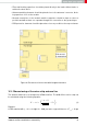

• Filter and blocking capacitors should be placed directly in the tracks without stubs, to
achieve the best effect.
• Antenna matching elements should be placed close to the antenna / connector, block-
ing capacitors close to the module.
• Ground connections for the module and the capacitors should be kept as short as
possible and with at least one separate through hole connection to the ground layer.
• ESD protection elements should be placed as close as possible to the exposed areas.
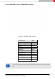
Figure 9: Placement of the module with integrated antenna
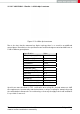
16.2 Dimensioning of the micro strip antenna line
The antenna track has to be designed as a 50Ω feed line. The width W for a micro strip can
be calculated using the following equation:
W = 1.25 ×
5.98 × H
e
50×
√
r
+1.41
87
− T
met
!
(3)
Example:
A FR4 material with ε
r
= 4.3, a height H = 1000 µm and a copper thickness of T
met
= 18 µm
Themisto-I reference manual version 1.0 © August 2019
www.we-online.com/wireless-connectivity 78