
User's Manual
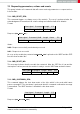
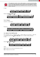

Start signal Command | 0x40 Length Status CS
0x02 0x4E 0x01 1 Byte 1 Byte
Status:
0x00: Request successfully received and processed
0x01: Request not successful
To wake-up from shut down mode, a falling edge has to be applied to the WAKE-UP pin.
In this case, the module restarts such that all volatile settings are lost. As soon as it has
restarted a
CMD_RESET_IND
message is printed on the UART. Please note that in shut down
mode, the WAKE-UP pin has an internal pull-down to ensure the wake-up is not performed
accidentally due to a floating pin.
7.3.4 CMD_STANDBY_REQ
This command triggers the standby mode of the chip, a low power mode with RAM retention.
The standby mode is entered after the command confirmation message is transmitted. The
UART interface is disabled in standby mode. The latency is smaller than the latency caused
by a complete restart of the module as done in the shut down mode.
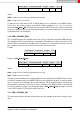
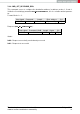
Format:
Start signal Command Length CS
0x02 0x0F 0x00 0x0D
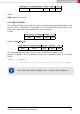
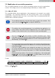
Response (
CMD_STANDBY_CNF
):
Start signal Command | 0x40 Length Status CS
0x02 0x4F 0x01 1 Byte 1 Byte
Status:
0x00: Request successfully received and processed
0x01: Request not successful
To wake-up from standby mode, a falling edge has to be applied to the WAKE-UP pin. Please
note that in standby mode, the WAKE-UP pin has an internal pull-down to ensure the wake-
up is not performed accidentally due to a floating pin. When a falling edge is detected, the
module wakes up but does not revert to factory settings as the RAM content is retained and
all volatile settings are kept. Upon being idle again, a
CMD_STANDBY_IND
message is printed
on the UART and the /RTS pin will show a low level.
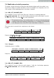
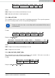
7.3.5 CMD_STANDBY_IND
This message indicates that the module woke up from standby mode and is ready for oper-
ation.
Themisto-I reference manual version 1.0 © August 2019
www.we-online.com/wireless-connectivity 29