Test report no. 19011843 EUT: 2609041191000 Themisto-I Page 1 of 116 FCC ID: R7T0904119 FCC Title 47 CFR Part 15 Date of issue: 2019-10-09 Annex acc. to FCC Title 47 CFR Part 15 relating to Würth Elektronik eiSoos GmbH Co. KG 2609041191000 Themisto-I Annex no. 5 User Manual Functional Description Title 47 - Telecommunication Part 15 - Radio Frequency Devices Subpart C – Intentional Radiators ANSI C63.4-2014 ANSI C63.10-2013 Date: 2019-03-11 Created: P4 TÜV NORD Hochfrequenztechnik GmbH & Co.
Test report no. 19011843 EUT: 2609041191000 Themisto-I Page 2 of 116 FCC ID: R7T0904119 FCC Title 47 CFR Part 15 Date of issue: 2019-10-09 User Manual / Functional Description of the test equipment (EUT) Date: 2019-03-11 Created: P4 TÜV NORD Hochfrequenztechnik GmbH & Co. KG LESKANPARK, Gebäude 10, Waltherstr. 49-51, 51069 Köln, Germany Reviewed: P9 Released: P1 Vers. No. 1.19 Tel.
T HEMISTO -I REFERENCE MANUAL 2609041191000 V ERSION 1.
Revision history Manual version FW version HW version 1.0 2.4.0 1.0 Notes • Initial version Date July 2019 ? For firmware history see chapter Firmware history Themisto-I reference manual version 1.0 www.we-online.
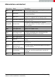
Abbreviations and abstract Abbreviation Name Description ACK Acknowledgement Acknowledgement pattern confirming the reception of the transmitted data packet. CS Checksum XOR checksum to check the correct transmission of the prepended Bytes. DC Duty cycle Transmission time in relation of one hour. 1% means, channel is occupied for 36 seconds per hour. FSE Field Sales Engineer Support and sales contact person responsible for limited sales area.
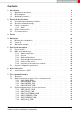
Contents 1 Introduction 1.1 Operational description . . . . . . . . . . . . . . . . . . . . . . . . . . . . . 1.2 Block diagram . . . . . . . . . . . . . . . . . . . . . . . . . . . . . . . . . . . 1.3 Ordering information . . . . . . . . . . . . . . . . . . . . . . . . . . . . . . . 2 Electrical specifications 2.1 Recommended operating conditions 2.2 Absolute maximum ratings . . . . . . 2.3 Power consumption . . . . . . . . . . 2.3.1 Static . . . . . . . . . . . . . 2.4 Radio characteristics . . . . . . .
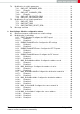
.4 . . . . . . . . . . . . . . . . . . . . . . . . . . . . . . . . . . . . . . . . . . . . . . . . 31 31 31 31 32 32 33 34 34 35 35 37 8 UserSettings - Module configuration values 8.1 Difference between volatile and non-volatile settings . . . . . . . . . . 8.2 Modifying the UserSettings . . . . . . . . . . . . . . . . . . . . . . . . 8.2.1 UART_Baudrate: Configure the UART speed . . . . . . . . . 8.2.1.1 Example 1 . . . . . . . . . . . . . . . . . . . . . . . . . . . 8.2.1.2 Example 2 . . . . . . .
.2.11 OpMode: Read the operating mode of the module . . . . . 8.2.11.1 Example 1 . . . . . . . . . . . . . . . . . . . . . . . . . 8.2.12 CfgFlags: Configure the configuration flags of the module 8.2.12.1 Example 1 . . . . . . . . . . . . . . . . . . . . . . . . . 8.2.12.2 Example 2 . . . . . . . . . . . . . . . . . . . . . . . . . 8.2.13 RpFlags: Configure the repeater flags of the module . . . 8.2.13.1 Example 1 . . . . . . . . . . . . . . . . . . . . . . . . . 8.2.13.2 Example 2 . . . . . . . . . . . .
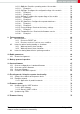
16 Design in guide 16.1 Advice for schematic and layout . . . . . . . . . . . . . . . . . . . . . . . . 16.2 Dimensioning of the micro strip antenna line . . . . . . . . . . . . . . . . . 16.3 Antenna solutions . . . . . . . . . . . . . . . . . . . . . . . . . . . . . . . 16.3.1 Wire antenna . . . . . . . . . . . . . . . . . . . . . . . . . . . . . 16.3.2 Chip antenna . . . . . . . . . . . . . . . . . . . . . . . . . . . . . 16.3.3 PCB antenna . . . . . . . . . . . . . . . . . . . . . . . . . . . . . 16.3.
23 Important notes 23.1 General customer responsibility . . . . . . . . 23.2 Customer responsibility related to specific, in plications . . . . . . . . . . . . . . . . . . . . 23.3 Best care and attention . . . . . . . . . . . . 23.4 Customer support for product specifications . 23.5 Product improvements . . . . . . . . . . . . . 23.6 Product life cycle . . . . . . . . . . . . . . . . 23.7 Property rights . . . . . . . . . . . . . . . . . 23.8 General terms and conditions . . . . . . . . .
1 Introduction 1.1 Operational description The Themisto-I is a radio sub module for wireless communication between devices such as control systems, remote controls, sensors etc. It offers several radio configurations, address modes and relieves the host system of radio-specific tasks as • checksum calculation, • address resolution • repetition of unacknowledged telegrams (if enabled) It can be deployed wherever the wireless exchange of data packets between two or more parties is required.
1.2 Block diagram Figure 1: Block diagram 1.3 Ordering information WE order code Former order code Description 2609041191009 Themisto-I DEV Development Kit: 3* Themisto-I radio module 915 MHz with antenna pad 2609041191000 Themisto-I Radio module 915 MHz with antenna pad, Tape & Reel Table 1: Ordering information Themisto-I reference manual version 1.0 www.we-online.
2 Electrical specifications As not otherwise stated measured on the evaluation board Themisto-I-EV with T=25°C, VDDS=3.3V, internal DC-DC converter active and a 50 Ω connection. Any radio transmission in the standard firmware uses boost mode independent of the chosen output power. 2.1 Recommended operating conditions Description Min. Typ. Max. Unit Ambient temperature -40 25 85 °C 1 3.0 3.7 V Supply voltage (VDDS) 2.
2.3 Power consumption As a DC/DC voltage regulator is integrated, the current consumption is strongly depending on the supplied voltage level. The transmit and receive currents are depending on the impedance matching, and therefore may vary depending on antenna selection and matching. The indicated values are the complete current consumption for radio and active MCU. Not to be confused with only radio or only CPU core currents, as sometimes stated by others.
Description Min Typ. Max Unit Frequency band 902.5 905 927.5 MHz Radio data rate 30 400 400 kbit/s RX sensitivity Profile 6 -99 dBm RX sensitivity Profile 8 -105 dBm RX sensitivity Profile 9 -111 dBm TX power 0 25 25 dBm Table 5: Radio characteristics 2.5 Pin characteristics Property typ. Value Unit Default GPIO maximum current 2 mA Maximum current of RX_IND,TX_IND 4 mA Pull up current (T=25°C, VDDS=1.8 V) 71.7 µA Pull down current (T=25°C, VDDS=1.8 V) 21.
3 Pinout 1 ANT 23 GND GND RESERVED VCC UTXD TX_IND URXD RX_IND /RTS /RESET RESERVED RESERVED RESERVED RESERVED RESERVED RESERVED RESERVED RESERVED WAKE-UP 13 i1 12 BOOT i4 RESERVED RESERVED TEST TEST TEST TEST Figure 2: Pinout (top view) Themisto-I reference manual version 1.0 www.we-online.
No Designation 1 ANT 2 GND Supply Ground 3 VCC Supply Supply voltage 4 UTXD Output UART module TX 5 URXD Input 6 /RTS Output 7 RESERVED I/O Reserved for future use. Uses an internal pull-up. Do not connect. 8 RESERVED I/O Reserved for future use. down. Do not connect. Uses an internal pull- 9 RESERVED I/O Reserved for future use. down. Do not connect. Uses an internal pull- 10 RESERVED I/O Reserved for future use. down. Do not connect.
No Designation I/O Description 13 RESERVED I/O Reserved for future use. down. Do not connect. 14 WAKE-UP Input 15 RESERVED I/O Reserved for future use. down. Do not connect. Uses an internal pull- 16 RESERVED I/O Reserved for future use. down. Do not connect. Uses an internal pull- 17 RESERVED I/O Reserved for future use. down. Do not connect. Uses an internal pull- 18 RESERVED I/O Reserved for future use. down. Do not connect.
4 Quickstart 4.1 Minimal pin configuration In factory state, the module is immediately ready for operation in command mode. The following pins are required in the minimal configuration: /RESET, BOOT, VCC, GND, /RTS, UTXD and URXD. The antenna pad ANT must be connected accordingly in case it is used. If the module is to be connected to a PC, a converter cable/IC (3.3V TTL to USB) is necessary to achieve interface compatibility.
Figure 3: Power up 4.3 Quickstart example Sending and receiving: Hello World Connect the two devices (modules, EV-boards or USB dongles) to a PC. You may need to install FTDI VCP drivers manually (see ) or using windows update. A minimum distance of 2 meters between the two devices should be kept at all time to avoid over modulation of the receiver. A terminal program, for example hterm, is used to perform the communication via COM ports.
To send the string "Hello World" the corresponding CMD_DATA_REQ has to be inserted into the input line of hterm. The "Type" needs to be change from "ASC" to "HEX" before entering the first byte. The command CMD_DATA_REQ has the following structure: Start signal Command Length Payload CS 0x02 0x00 1 Byte Length Bytes 1 Byte In this example the payload 0x48 0x65 0x6C 0x6C 0x6F 0x20 0x57 0x6F 0x72 0x6C 0x64 0x21 (Hello World!) has a length of 12 (0x0C) Bytes.
5 Functional description The Themisto-I can be configured to operate in several modes at the physical, MAC as well as the network layer. This chapter describes all the available modes of operation. 5.1 Physical layer At the physical layer, the Themisto-I can be configured to use one of the following radio profiles (see parameter RADIO_DefaultRfProfile).
Please note that the RF settings (e.g. RF profile, RF channel, address mode, repeater settings) must be the same for all nodes in the network. Violation may cause interrupted transmission, or received packets that cannot to be interpreted correctly. In addition, the timing parameters in case of repeater or enabled ACKs must be the same for all nodes in a network. The address mode 3 (254 network ids and 65534 addresses) is only supported by the Tarvos-II and Tarvos-III.
Please note that each CMD_SET_REQ will consume one flash erase/write cycle, which are limited due to the hardware (guaranteed are 100k cycles, see TI CC1310 datasheet). On the other hand, the volatile settings (called "RuntimeSettings") can be accessed by explicit commands (see chapter 7.4) and used to quickly (but temporarily) modify specific parameters without using flash cycles. These settings are only valid until a reset is performed and shall be used when frequent updates of settings are necessary.
6 Host connection 6.1 Serial interface: UART The configuration in factory state of the UART is 115200 baud with data format of 8 data Bits, no parity and 1 stop Bit ("8n1"). The baud rate of the UART can be configured by means of the UserSetting UART_Baudrate. The data format is fixed to 8n1. The output of characters on the serial interface runs with secondary priority. For this reason, short interruptions may occur between the outputs of individual successive Bytes.
7 The command interface 7.1 Overview The module acts as a slave and can be fully controlled by an external host. The configuration as well as the operation of the module can be managed by predefined commands that are sent as telegrams over the UART interface of the module. The commands of the command interface can be divided into 3 groups: • Requests: The host requests the module to trigger any action, e.g. in case of the request CMD_RESET_REQ the host asks the module to perform a reset.
7.2 Data transfer and reception in the command mode This group of commands include the commands that either are used to request a radio telegram to be send or indicates a received frame. 7.2.1 CMD_DATA_REQ This command serves the simple data transfer in the command mode. Transmission takes place on the configured channel to the previously parametrised destination address (taken from the volatile RuntimeSettings). This command is especially suitable for transmission for a point-to-point connection.
Start signal Command Length Channel Payload CS 0x02 0x01 Payload len. + 1 1 Byte Payload len. Bytes 1 Byte Address mode 1: Start signal Command Length 0x01 Payload len. + 2 0x02 Channel 1 Byte Dest. address Payload CS 1 Byte Payload len. Bytes 1 Byte Address mode 2: Start signal Command Length 0x01 Payload len. + 3 1 Byte 1 Byte Command Length Channel Dest. netID 0x01 Payload len. + 4 0x02 Channel Dest. netID Dest. address Payload CS 1 Byte Payload len.
7.2.3 CMD_DATAEX_IND This telegram indicates the reception of data Bytes and represents the counterpart to the commands CMD_DATA_REQ and CMD_DATAEX_REQ. Apart from the RX field strength (RSSI value given in two’s complement notation), this telegram also displays the source address of the sending device (depending on the parametrised address mode). Please note that the format of this command depends on the configured MAC_DefaultAddressMode.
7.2.4 CMD_REPEAT_IND This command indicates that the module has repeated a data packet when acting in repeater mode. The source address and network id is the address of the origin sender of the RF packet, the destination address and network id is the address of the device that is supposed to receive the RF packet. Format in address mode 0: Start signal Command Length Status Address mode CS 0x02 0x80 0x02 1 Byte 0x00 1 Byte Dest.
7.3 Requesting parameters, actions and events This group includes all commands that will return read-only parameters or request actions in the module. 7.3.1 CMD_RESET_REQ This command triggers a software reset of the module. The reset is performed after the acknowledgment is transmitted. All volatile settings are initialized with their defaults.
Start signal Command | 0x40 Length Status CS 0x02 0x4E 0x01 1 Byte 1 Byte Status: 0x00: Request successfully received and processed 0x01: Request not successful To wake-up from shut down mode, a falling edge has to be applied to the WAKE-UP pin. In this case, the module restarts such that all volatile settings are lost. As soon as it has restarted a CMD_RESET_IND message is printed on the UART.
Start signal Command | 0x80 Length Status CS 0x02 0x8F 0x01 0x00 0x8C Status: 0x00: wake-up successful 7.3.6 CMD_RSSI_REQ This command returns the RX level of the last received packet determined by the transceiver IC in the form of a signed two’s complement. The current RSSI value of the radio IC ("live RSSI value") cannot be requested by means of this command.
7.4 Modification of volatile parameters This group contains all functions that will modify RuntimeSettings while the module is running. These settings are volatile and will be reset to their defaults (see chapter 8) on a reset of the module or when waking up after a shut down command. 7.4.1 CMD_SET_PAPOWER_REQ This command is used to set the radio TX-power. Unlike the UserSettings parameter RADIO_DefaultRfTXPower, this is a volatile runtime parameter, but it’s power value is used in the same way.
The parameter must be chosen with prudence to reach good functionality (radio environment dependent) and compliance with valid regulatory requirements as the EN 300 220 in the European Union or the FCC in the United States of America. Format: Start signal Command Length Channel CS 0x02 0x06 0x01 1 Byte 1 Byte Response (CMD_SET_CHANNEL_CNF): Start signal Command | 0x40 Length Configured channel CS 0x02 0x46 0x01 1 Byte 1 Byte 7.4.2.
7.4.4 CMD_SET_DESTADDR_REQ This command serves to configure the destination address in address modes 1, 2 and 3. Unlike the UserSettings parameter MAC_DefaultDestAddr, this is a volatile runtime parameter. Format: Mode 1 + 2: Start signal Command Length Dest.
7.5 Modification of non-volatile parameters The non-volatile parameters are also called UserSettings and are stored in a special flash location. This settings can also be configured using our windows pc software "ACC". 7.5.1 CMD_SET_REQ This command enables direct manipulation of the parameters in the module’s non-volatile UserSettings. The respective parameters are accessed by means of the corresponding SettingsIndex.
Start signal Command | 0x40 Length Status CS 0x02 0x49 0x01 1 Byte 1 Byte Status: 0x00: Request successfully received and processed 0x01: Operation failed due to invalid parameter 7.5.2 CMD_GET_REQ This command can be used to query the UserSettings parameters. The respective parameters are accessed by means of the corresponding SettingsIndex. Parameters with size of two or more Bytes will be transmitted LSB first unless noted otherwise.
Start signal Command | 0x40 Length Status CS 0x02 0x52 0x01 1 Byte 1 Byte Status: 0x00: Request successfully received and processed 0x01: Request not successful Themisto-I reference manual version 1.0 www.we-online.
7.
8 UserSettings - Module configuration values 8.1 Difference between volatile and non-volatile settings The so-called UserSettings are stored permanently into the internal flash of the module. At start-up, these UserSettings are loaded as start values into the volatile settings ("RuntimeSettings"). Some of the RuntimeSettings can be modified by special commands (see chapter 7.4). These RuntimeSettings are lost and replaced by the UserSettings content when the module is restarted. See chapters 7.4 and 7.
Please double check that the Byte-order of the parameter. It is to be used L̈SB first¨. Wrong values may lead to a condition where talking with the module is not possible anymore. 8.2.1.
8.2.2 RADIO_DefaultRfProfile: Configure the RF-settings Settings index Designation Permissible values Default value Permissions Number of Bytes 1 RADIO_DefaultRfProfile 6,8,9 6 read/write 1 The UserSetting RADIO_DefaultRfProfile is an 8 Bit field that addresses the applied RF configuration. The parameter must be chosen with prudence to reach good functionality and compliance with valid regulatory requirements as the FCC in the United States of America.
8.2.2.2 Example 2 Request the radio profile using CMD_GET_REQ: Start signal Command Length Settings index CS 0x02 0x0A 0x01 0x01 0x08 Response CMD_GET_CNF: Successfully read out the radio as 6. Start signal Command | 0x40 Length Status Parameter CS 0x02 0x4A 0x02 0x00 0x06 0x4C Themisto-I reference manual version 1.0 www.we-online.
8.2.3 RADIO_DefaultRfTXPower: Configure the RF TX-power Settings index Designation Permissible values Default value Permissions Number of Bytes 2 RADIO_DefaultRfTXPower 12, 18, 21, 23, 24, 25 25 read/write 1 This UserSetting defines the radio output power of the module. The UserSettings parameter RADIO_DefaultRfTXPower is entered as a complement on two. This value represents the power at the radio ic without taking the antenna into account.
8.2.4 RADIO_DefaultRfChannel: Configure the RF channel Settings index Designation Permissible values Default value Permissions Number of Bytes 3 RADIO_DefaultRfChannel 201 - 251 226 read/write 1 This UserSetting determines the wireless channel of the module to be used after a reset. The dependence between channel and frequency is as follows: ChannelRF = F requencyRF − 802M Hz 0.5M Hz (1) Check chapter 10.1 for more information.
8.2.5 MAC_DefaultAddressMode: Configure the address mode Settings index Designation Permissible values Default value Permissions Number of Bytes 4 MAC_DefaultAddressMode 0-3 0 read/write 1 This setting defines the address mode of the module. The following modes have been implemented: No addressing (mode 0): Each module receives the transmitted RF telegram and delivers the received data to the host system via UART. No address information is transmitted in the radio telegram.
The receiver and transmitter modules must always operate in the same address mode! Otherwise, the receiver cannot interpret the received data packet meaning that the packet is discarded! 8.2.5.1 Example 1 Set the address mode to 2 using the CMD_SET_REQ: Start signal Command Length Settings index Parameter CS 0x02 0x09 0x02 0x04 0x02 0x0F Response CMD_SET_CNF: Successfully modified the setting. Start signal Command | 0x40 Length Status CS 0x02 0x49 0x01 0x00 0x4A 8.2.5.
8.2.6 MAC_NumRetrys: Configure the number of retries Settings index Designation Permissible values Default value Permissions Number of Bytes 6 MAC_NumRetrys 0 - 255 0 read/write 1 This UserSetting determines the maximum number of wireless transmission retries. If this parameter is set to a value other than zero, the receiver module will automatically be prompted to send a wireless acknowledgement ("ACK").
8.2.7 MAC_DefaultDestNetID: Configure the destination network id Settings index Designation Permissible values Default value Permissions Number of Bytes 7 MAC_DefaultDestNetID 0 - 255 255 read/write 1 This UserSetting specifies the default destination network ID, which is used in address modes 2 and 3. If the special broadcast id and the broadcast address are set to 255, the packets will be received by all network participants.
8.2.8 MAC_DefaultDestAddr: Configure the destination address Settings index Designation Permissible values Default value Permissions Number of Bytes 8 MAC_DefaultDestAddr 0 - 65535 65535 read/write 1-2 This UserSetting specifiest destination address, which is used in address modes 1, 2 and 3. If a broadcast address (255 in addressmodes 1 and 2, or 65535 in address mode 3) is used, the packets will be received by all network participants or by participants in the same network id.
Start signal Command Length Settings index CS 0x02 0x0A 0x01 0x08 0x01 Response CMD_GET_CNF: Successfully read out the default destination address as 0 (0x0000). The 2 byte parameter has the order LSB first. The return value of this Settings index is always read as 2 byte parameter. Start signal Command | 0x40 Length Status Parameter CS 0x02 0x4A 0x03 0x00 0x00 0x00 0x4B Themisto-I reference manual version 1.0 www.we-online.
8.2.9 MAC_SourceNetID: Configure the source network id Settings index Designation Permissible values Default value Permissions Number of Bytes 10 MAC_SourceNetID 0 - 254 0 read/write 1 This UserSetting specifies the source network id to be used in address modes 2 and 3. Setting the Source Net ID to Broadcast (255) is not allowed. 8.2.9.
8.2.10 MAC_SourceAddr: Configure the source address Settings index Designation Permissible values Default value Permissions Number of Bytes 11 MAC_SourceAddr 0 - 65534 0 read/write 1-2 This UserSetting specifies the source device address to be used in address modes 1, 2 and 3. The LSB corresponds to the first byte in "parameter" the MSB (if used) to the second byte.
Start signal Command Length Settings index CS 0x02 0x0A 0x01 0x0B 0x02 Response CMD_GET_CNF: Successfully read out the source address as 2 (0x0002). The 2 byte parameter is to be used LSB first. Start signal Command | 0x40 Length Status Parameter CS 0x02 0x4A 0x03 0x00 0x02 0x00 0x49 Themisto-I reference manual version 1.0 www.we-online.
8.2.11 OpMode: Read the operating mode of the module Settings index Designation Permissible values Default value Permissions Number of Bytes 14 OpMode 16 16 read 1 The OpMode 0x10 (16) is indicating that the module is in command mode. Currently no other OpMode is available. 8.2.11.
8.2.12 CfgFlags: Configure the configuration flags of the module Settings index 15 Designation Permissible values Default value Permissions Number of Bytes CfgFlags See description 0 read/write 2 This parameter is used for the general module configuration. Repeater and sniffer mode cannot be enabled at the same time. A module configured as sniffer will not send any ACKs even if requested by the sender. Bit no. Filter Description 0 0x0001 Set this Bit to ’1’ to enable the sniffer mode.
Start signal Command | 0x40 Length Status Parameter CS 0x02 0x4A 0x03 0x00 0x00 0x00 0x4B Themisto-I reference manual version 1.0 www.we-online.
8.2.13 RpFlags: Configure the repeater flags of the module Settings index Designation Permissible values Default value Permissions Number of Bytes 16 RpFlags See description 0 read/write 2 This parameter is used for the repeater configuration. See chapter 13 for more information about the repeater mode. Repeater and sniffer mode cannot be enabled at the same time. The repeater function shall not be enabled in radio profiles 3 and 4.
Start signal Command | 0x40 Length Status CS 0x02 0x49 0x01 0x00 0x4A 8.2.13.2 Example 2 Request the repeater flags using CMD_GET_REQ: Start signal Command Length Settings index CS 0x02 0x0A 0x01 0x10 0x19 Response CMD_GET_CNF: Successfully read out the value of RpFlags. The 2 byte parameter is to be used LSB first. A parameter value 0x0000 indicates that the repeater mode is disabled. A value of 0x0001 indicates that the repeater mode is enabled.
8.2.14 RP_NumSlots: Configure the repeater data base Settings index Designation Permissible values Default value Permissions Number of Bytes 17 RP_NumSlots 1 -255 32 read/write 1 An 8 Bit field that contains the number of time slots to be used for the packet repetition. When using several repeater devices in a single network, repeated data packets may collide on the frequency channel, when all repeater devices send the received packet at the same time.
Start signal Command Length Settings index Parameter CS 0x02 0x09 0x02 0x11 0x40 0x58 Response CMD_SET_CNF: Successfully modified the setting. Start signal Command | 0x40 Length Status CS 0x02 0x49 0x01 0x00 0x4A 8.2.14.2 Example 2 Request the number of repeater slots using CMD_GET_REQ: Start signal Command Length Settings index CS 0x02 0x0A 0x01 0x11 0x18 Response CMD_GET_CNF: Successfully read out the number of repeater slots as 32 (0x20).
8.2.15 FactorySettings: Read out the factory settings Settings index Designation Permissible values Default value Permissions Number of Bytes 32 FactorySettings - - read 8 This parameter defines the factory settings of the module. Byte no. Description 3:0 Serial number: 3 byte ID (LSB first), 1 byte PID 6:4 Hardware version: Major , Minor, Patch 7 Frequency correction factor 8.2.15.
8.2.16 FirmwareVersion: Read out the firmware version Settings index 33 Designation Permissible values Default value Permissions Number of Bytes FirmwareVersion - - read 3 This parameter defines the version of the firmware currently running on the module. 8.2.16.1 Example 1 Request the factory settings of the module using CMD_GET_REQ: Start signal Command Length Settings index CS 0x02 0x0A 0x01 0x21 0x28 Response CMD_GET_CNF: Successfully read out the firmware version as 2.1.0.
9 Timing parameters 9.1 Reset behavior Following a reset, a CMD_RESET_IND and a stable low level on the /RTS pin signalizes that the module is ready for operation. During restart the /RTS may be pulled to GND level for a short time (<100µs, see figure 4) until it is configured accordingly by the application on the module. 9.1.1 Reset via /RESET pin To force a module restart by means of the /RESET pin, it must first be drawn to low for at least 100µs.
Figure 4: Wake-up from standby 9.2.2 Wake-up latency from shutdown The wake-up time from shutdown is 5 ms. Figure 5: Wake-up from shutdown 9.3 Latencies during data transfer / packet generation The data transfer is always buffered, i.e. data received via UART is buffered in the module until a specific event occurs (i.e. packet completed with the CS field of a command).
10 Radio parameters The default radio parameters are determined by the values of RADIO_DefaultRfProfile, RADIO_DefaultRfChannel and RADIO_DefaultRfTXPower in the user settings. These nonvolatile parameters can be modified using CMD_SET_REQ. To modify their volatile counterparts the commands CMD_SET_PAPOWER_REQ and CMD_SET_CHANNEL_REQ can be used.
Channel 200 201 202 203 204 205 206 207 208 209 210 211 212 213 214 215 216 217 218 219 220 221 222 223 224 225 226 Frequency [MHz] 902 902.5 903 903.5 904 904.5 905 905.5 906 906.5 907 907.5 908 908.5 909 909.5 910 910.5 911 911.5 912 912.5 913 913.5 914 914.
11 Battery powered operation For battery-powered operation, the module provides two sleep modes. Each mode can be entered by a specific command and left by applying a falling edge at the WAKE-UP pin. Shutdown Standby Enter mode By command CMD_SHUTDOWN_REQ By command CMD_STANDBY_REQ Typical current consumption [µA] 0.9 2 Wake-up trigger Falling edge at the WAKE-UP pin CPU wake-up time [ms] See chapter 9 Wake-up behavior The module restarts such that all volatile settings are lost.
12 Custom firmware 12.1 Custom configuration of standard firmware The configuration of standard firmware includes adoption of the non-volatile Usersettings (see chapter 8) to customer requirements and creating a customized product on base of the standard product with a unique ordering number for a specific customer that needs this configuration. For example if the UART baud rate shall be changed from the default value to another value.
The qualification(s) and certification(s) of the standard firmware cannot be applied to this customer firmware solution without a review and verification. 12.4 Contact for firmware requests Please contact your local field sales engineer (FSE) or wireless-sales@we-online.com for quotes regarding this topics. Themisto-I reference manual version 1.0 www.we-online.
13 Flooding mesh: Using the repeater functionality The module can be run as a repeater to artificially extend the range of sending devices in an existing network. If the module is configured as repeater, it can be simply added to existing Figure 6: Range extension using several repeaters wireless networks consisting of compatible modules. With this, the newly generated mesh network uses the so-called "flooding technique" to deliver data packets from their source to their destination device.
13.1 Setup of the network and repeater device The repeater mode can be enabled with setting Bit 0 accordingly in the RpFlags. As ACKs are not supported by the repeater mode all network members must make sure that the UserSettings value of MAC_NumRetrys is set to 0. If the module is configured as repeater, the following notes have to be considered: 1. Requirements on the network: a) The repeater devices have to be line-powered (no battery), since due to packet repetition it demands more energy.
c) Every repeater sends each packet only once. However, receivers can receive each packet several times (sent by different repeaters), if there are packets of different content in the network temporally close to each other. Thus, on the side of the receiving device, a mechanism shall be implemented that detects and filters double packets. 13.2 Example network Figure 7: Example network In the example network shown above, the goal is to send a packet from device 1 to 5.
ii. Repeater 2 does not accept it, since it has been already received before (1.2). b) Repeater 2 sends the packet. i. Repeaters 3 does not accept it, since it has been already received before (1.3). ii. Sender 1 does not accept it, since its address is wrong (unequal 5). iii. Repeater 4 receives and accepts the packet. 3. Repeater 4 delays and sends the packet. a) Sender 6 and 7 do not accept it, since their addresses are wrong (unequal 5).
14 Firmware update We highly recommend having the UART or JTAG accessible in any application to have the possibility to perform a firmware update. Firmware updates can only be performed through this interfaces once a module is implemented into a customer PCB. Flashing a customer or non standard firwmare makes all regulatory and conformity information and certificates of chapter 22 invalid. 14.1 Update using the UART interface Only the UTDX, URXD and GND signals are needed for this connection.
14.2 Update using JTAG Using this interface option allows performing a fail-safe firmware update even in case of a broken firmware or misconfiguration. The user needs hardware and software tools to be able to perform this procedure. In detail those are: • Flash adapter for Cortex M µC supporting TI CC1310 (Not every adapter supports the used connection methods).
15 Firmware history Version 2.4.0 "Release" • Initial release. • Known issues: – TI-RTOS: Additional latencies up to 5ms due to task priorities may occur. – In case a CMD_DATAEX_REQ is used with a wrong channel number, the module answers with a CMD_DATAEX_CNF (0x02 0x41 0x01 0x02 0x40) instead of a CMD_DATA_CNF (0x02 0x40 0x01 0x02 0x41) message. Themisto-I reference manual version 1.0 www.we-online.
16 Design in guide 16.1 Advice for schematic and layout For users with less RF experience it is advisable to closely copy the relating evaluation board with respect to schematic and layout, as it is a proven design. The layout should be conducted with particular care, because even small deficiencies could affect the radio performance and its range or even the conformity. The following general advice should be taken into consideration: • A clean, stable power supply is strongly recommended.
• Elements for ESD protection should be placed on all pins that are accessible from the outside and should be placed close to the accessible area. For example, the RF-pin is accessible when using an external antenna and should be protected. • ESD protection for the antenna connection must be chosen such as to have a minimum effect on the RF signal. For example, a protection diode with low capacitance such as the LXES15AAA1-100 or a 68 nH air-core coil connecting the RF-line to ground give good results.
• Filter and blocking capacitors should be placed directly in the tracks without stubs, to achieve the best effect. • Antenna matching elements should be placed close to the antenna / connector, blocking capacitors close to the module. • Ground connections for the module and the capacitors should be kept as short as possible and with at least one separate through hole connection to the ground layer. • ESD protection elements should be placed as close as possible to the exposed areas.
Figure 10: Dimensioning the antenna feed line as micro strip will lead to a trace width of W ∼ 1.9 mm. To ease the calculation of the micro strip line (or e.g. a coplanar) many calculators can be found in the internet. • As rule of thumb a distance of about 3×W should be observed between the micro strip and other traces / ground. • The micro strip refers to ground, therefore there has to be the ground plane underneath the trace. • Keep the feeding line as short as possible. 16.
16.3.1 Wire antenna An effective antenna is a λ/4 radiator with a suiting ground plane. The simplest realization is a piece of wire. It’s length is depending on the used radio frequency, so for example 8.6 cm 868.0 MHz and 3.1 cm for 2.440 GHz as frequency. This radiator needs a ground plane at its feeding point. Ideally, it is placed vertically in the middle of the ground plane.
16.3.4 Antennas provided by Würth Elektronik eiSos 16.3.4.1 2600130011 - Helike - 169 MHz dipole antenna Figure 11: 169 MHz dipole-antenna Specification Value Frequency range [MHz] 169 Impedance [Ω] 50 VSWR ≤ 2.1 Gain [dBi] 1 Dimensions (L x d) [mm] 320 x 15 Weight [g] 42 Connector SMA plug Operating Temp. [°C] -40 – +85 This antenna requires a ground plane which will influence the electrical parameters. Themisto-I reference manual version 1.0 www.we-online.
16.3.4.2 2600130041 - Herse - 434 MHz dipole antenna Figure 12: 434 MHz dipole-antenna Specification Value Frequency range [MHz] 433 Impedance [Ω] 50 VSWR ≤ 1.5 Polarization Vertical Radiation Omni Gain [dBi] 0 Antenna Cover TPEE Dimensions (L x d) [mm] 90 x 12 Weight [g] 9.6 Connector SMA plug Operating Temp. [°C] -40 – +80 This antenna requires a ground plane which will influence the electrical parameters. Themisto-I reference manual version 1.0 www.we-online.
16.3.4.3 2600130081 - Hyperion-I - 868 MHz dipole antenna Figure 13: 868 MHz dipole-antenna Ideally suited for applications where no ground plane is available. The 2600130081 antenna can be also used for 902MHz - 928MHz range. Specification Value Center frequency [MHz] 868 Frequency range [MHz] 853 – 883 Wavelength 0.5 wave VSWR ≤ 2.0 Impedance [Ω] 50 Connector SMA (Male) Dimensions (L x d) [mm] 142 x 10 Peak gain [dBi] -2.3 Operating temp.
16.3.4.4 2600130082 - Hyperion-II - 868 MHz magnetic base antenna Well suited for applications where the RF is lead through a metal wall that could serve as ground plane to the antenna. Figure 14: 868 MHz magnet foot antenna with 1.5 m antenna cable The 2600130082 is a kind of λ/4 radiator and therefore needs a ground plane at the feeding point. Specification Value Frequency range [MHz] 824 – 894 VSWR ≤ 2.
16.3.4.5 2600130021 - Himalia - 2.4 GHz dipole antenna Figure 15: 2.4 GHz dipole-antenna Due to the fact, that the antenna has dipole topology there is no need for an additional ground plane. Nevertheless the specification was measured edge mounted and 90° bent on a 100 x 100 mm ground plane. Specification Value Frequency range [GHz] 2.4 – 2.5 Impedance [Ω] 50 VSWR ≤ 2:1 Polarization Linear Radiation Omni-Directional Peak Gain [dBi] 2.8 Average Gain [dBi] -0.
17 Reference design Themisto-I was tested and certified on the corresponding Themisto-I evaluation board. For the compliance with the FCC §15.247, the evaluation board serves as reference design. This is no discrepancy due to the fact that the evaluation board itself does not fall within the scope of FCC §15.247 according to 47 CFR §2.803 (c) exemptions (iv) evaluation kit, as the module is tested on the evaluation board, which is also the recommended use.
17.1 Schematic Themisto-I reference manual version 1.0 www.we-online.
Themisto-I reference manual version 1.0 www.we-online.
17.2 Layout Figure 16: Assembly diagram Themisto-I reference manual version 1.0 www.we-online.
Figure 17: Top and Bottom Layer Themisto-I reference manual version 1.0 www.we-online.
18 Manufacturing information 18.1 Moisture sensitivity level This wireless connectivity product is categorized as JEDEC Moisture Sensitivity Level 3 (MSL3), which requires special handling. More information regarding the MSL requirements can be found in the IPC/JEDEC J-STD-020 standard on www.jedec.org. More information about the handling, picking, shipping and the usage of moisture/reflow and/or process sensitive products can be found in the IPC/JEDEC J-STD-033 standard on www.jedec.org. 18.
Package thickness Volume mm3 <350 Volume mm3 350-2000 Volume mm3 >2000 < 1.6mm 260°C 260°C 260°C 1.6mm - 2.5mm 260°C 250°C 245°C > 2.5mm 250°C 245°C 245°C Table 12: Package classification reflow temperature, PB-free assembly, Note: refer to IPC/JEDEC J-STD-020E It is recommended to solder this module on the last reflow cycle of the PCB. For solder paste use a LFM-48W or Indium based SAC 305 alloy (Sn 96.5 / Ag 3.0 / Cu 0.5 / Indium 8.9HF / Type 3 / 89%) type 3 or higher.
18.2.2 Cleaning Do not clean the product. Any residue cannot be easily removed by washing. Use a "no clean" soldering paste and do not clean the board after soldering. • Do not clean the product with water. Capillary effects can draw water into the gap between the host PCB and the module, absorbing water underneath it. If water is trapped inside, it may short-circuit adjoining pads. The water may also destroy the label and ink-jet printed text on it.
• Do not touch any exposed area of the antenna to avoid electrostatic discharge. Do not let the antenna area be touched in a non ESD-safe manner. • When soldering, use an ESD-safe soldering iron. 18.4 Safety recommendations It is your duty to ensure that the product is allowed to be used in the destination country and within the required environment. Usage of the product can be dangerous and must be tested and verified by the end user.
19 Physical dimensions 19.1 Dimensions Dimensions 17 x 27 x 3.8 mm Table 13: Dimensions 19.2 Weight Weight 3g Table 14: Weight Themisto-I reference manual version 1.0 www.we-online.
19.3 Module drawing 24,0 12 23 2,0 13 4,0 1,5 14,0 1 1,0 3,8 ±0,2 22,0 17,0 ±0,4 27,0 ±0,4 Figure 19: Module dimensions [mm] Themisto-I reference manual version 1.0 www.we-online.
19.4 Footprint 22,0 1,5 2,0 4,0 1,0 18,0 6,0 2,0 2,2 4,0 24,0 Figure 20: Footprint and dimensions [mm] The following points have to be considered: • To avoid the risk of short circuits, a minimum clearance of at least 14 mm between the opposing pad rows has to be maintained! No routing on the top layer of a carrier PCB (i.e. "under" the module) shall be performed. • For the module variant with integrated antenna the marked corner area of 7.3 x 13.8 mm has to be kept free from metal, on any layer.
20 Marking 20.1 Lot number The 15 digit lot number is printed in numerical digits as well as in form of a machine readable bar code. It is divided into 5 blocks as shown in the following picture and can be translated according to the following table. Figure 21: Lot number structure Block Information Example(s) 1 eiSos internal, 3 digits 439 2 eiSos internal, 2 digits 01 3 Hardware version, 3 digits V2.4 = 024, V12.
20.2 General labeling information The module labels may include the following fields: • Manufacturer identification WE, Würth Elektronik or Würth Elektronik eiSos • WE Order Code and/or article alias • Serial number or MAC address • Certification identifiers (CE, FCC ID, IC, ARIB,...) • Bar code or 2D code containing the serial number or MAC address The serial number includes the product ID (PID) and an unique 6 digit number. The first 1 to 3 digits represent the PID, then the ".
21 Information for Ex protection In case the end product should be used in Ex protection areas the following information can be used: • The module itself is unfused. • The maximum output power of the module is 25dBm. • The total amount of capacitivity of all capacitors is 56.7µF. • The total amount of inductivity of all inductors is 6.9 µH. Themisto-I reference manual version 1.0 www.we-online.
22 Regulatory compliance information 22.1 Important notice FCC The use of RF frequencies is limited by national regulations. The Themisto-I has been designed to comply with the FCC Part 15. The Themisto-I can be operated without notification and free of charge in the area of the United States of America. However, according to the FCC Part 15, restrictions (e.g. in terms of maximum allowed RF power and antenna) may apply. 22.2 Conformity assessment of the final product The Themisto-I is a subassembly.
22.4 FCC Compliance Statement FCC ID: R7T0904119 This device complies with Part 15 of the FCC Rules. Operation is subject to the following two conditions: (1) this device may not cause harmful interference, and (2) this device must accept any interference received, including interference that may cause undesired operation. (FCC 15.19) Modifications (FCC 15.
• A label must be affixed to the outside of the host product with the following statements: This device contains FCCID: R7T0904119 This equipment contains equipment certified under ICID: 5136A-0904119 • The final host / module combination may also need to be evaluated against the FCC Part 15B criteria for unintentional radiators in order to be properly authorized for operation as a Part 15 digital device.
• The OEM shall perform testing in accordance to 996369 D04 Module Integration Guide V01. 22.7 Pre-certified antennas The certification is valid for antennas with gain smaller than 1.7dB, for example: • 1/2 dipole (1.6dBi). • 1/4 wave ground plane antenna (0.3dBi). Using antennas with higher gain the requirements for power spectrum density might be violated for radio profile 9. Using other antennas, the integrator has to retest and either reduce the output power or limit the duty cycle.
23 Important notes The following conditions apply to all goods within the wireless connectivity product range of Würth Elektronik eiSos GmbH & Co. KG: 23.1 General customer responsibility Some goods within the product range of Würth Elektronik eiSos GmbH & Co. KG contain statements regarding general suitability for certain application areas.
23.5 Product improvements Due to constant product improvement, product specifications may change from time to time. As a standard reporting procedure of the Product Change Notification (PCN) according to the JEDEC-Standard, we inform about major changes. In case of further queries regarding the PCN, the field sales engineer, the internal sales person or the technical support team in charge should be contacted. The basic responsibility of the customer as per section 23.1 and 23.2 remains unaffected.
24 Legal notice 24.1 Exclusion of liability Würth Elektronik eiSos GmbH & Co. KG considers the information in this document to be correct at the time of publication. However, Würth Elektronik eiSos GmbH & Co. KG reserves the right to modify the information such as technical specifications or functions of its products or discontinue the production of these products or the support of one of these products without any written announcement or notification to customers.
a failure of the product is reasonably expected to cause severe personal injury or death, unless the parties have executed an agreement specifically governing such use. Moreover, Würth Elektronik eiSos GmbH & Co. KG products are neither designed nor intended for use in areas such as military, aerospace, aviation, nuclear control, submarine, transportation (automotive control, train control, ship control), transportation signal, disaster prevention, medical, public information network etc.
25 License terms This License Terms will take effect upon the purchase and usage of the Würth Elektronik eiSos GmbH & Co. KG wireless connectivity products. You hereby agree that this license terms is applicable to the product and the incorporated software, firmware and source codes (collectively, "Software") made available by Würth Elektronik eiSos in any form, including but not limited to binary, executable or source code form.
design-in stage. In certain customer applications requiring a very high level of safety and in which the malfunction or failure of an electronic component could endanger human life or health, you must ensure to have all necessary expertise in the safety and regulatory ramifications of your applications.
25.6 Limitation of liability Any liability not expressly provided by Würth Elektronik eiSos shall be disclaimed. You agree to hold us harmless from any third-party claims related to your usage of the Würth Elektronik eiSos’ products with the incorporated Firmware, software and source code. Würth Elektronik eiSos disclaims any liability for any alteration, development created by you or your customers as well as for any combination with other products. 25.
List of Figures 1 2 3 4 5 6 7 8 9 10 11 12 13 14 15 16 17 18 19 20 21 22 Block diagram . . . . . . . . . . . . . . . . . . . . . . . . Pinout (top view) . . . . . . . . . . . . . . . . . . . . . . Power up . . . . . . . . . . . . . . . . . . . . . . . . . . Wake-up from standby . . . . . . . . . . . . . . . . . . . Wake-up from shutdown . . . . . . . . . . . . . . . . . . Range extension using several repeaters . . . . . . . . Example network . . . . . . . . . . . . . . . . . . . . . . Layout . . . . . . .
more than you expect Internet of Things Contact: Würth Elektronik eiSos GmbH & Co. KG Division Wireless Connectivity & Sensors Rudi-Schillings-Str. 31 54296 Trier Germany Tel.: +49 651 99355-0 Fax.: +49 651 99355-69 www.we-online.