Chelton Avionics Inc. A Chelton Group Company 6400 Wilkinson Drive Prescott, AZ 86305 U.S.A. Series III Avionics Pilot's Guide Publication No. 150-040564 Rev.
Series III Avionics Pilot's Guide Wulfsberg Electronics Division, located in Prescott, Arizona, designs and manufactures the Chelton Series III line of products, including the VCS-40A VHF Communications System. For more than 25 years, Wulfsberg Electronics has distinguished itself by providing top quality avionics products for civil, air transport, and military applications. Information in this manual is subject to change without notice.
Series III Avionics Pilot's Guide VCS-40A VHF Communications System...................................................................................................................1 General Description................................................................................................................................................1 CD-402B Control Display Unit ..............................................................................................................................
Series III Avionics Pilot's Guide VCS-40A VHF Communication System General Description The Chelton VCS-40A VHF Communications System is a fully synthesized ATC VHF transceiver. The VCS-40A system consists of a lightweight, remote-mounted VC-401B transceiver and a panel-mounted CD-402B Control Display Unit. The VC-401B transceiver is available with fixed 25 kHz channel spacing, fixed 8.33 kHz channel spacing for European airspace, and switchable 25 kHz - 8.33 kHz channel spacing.
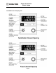
Series III Avionics Pilot's Guide CD-402B Control Display Unit Page 2
Series III Avionics Pilot's Guide CD-402B Controls (Switchable Channel Spacing) Off/On Channel Spacing Selector and TEST Pushbutton OFF - Deactivates the VCS-40A System. Records the last frequencies displayed in the system's non-volatile memory. 25 - Activates the VCS-40A System. Selects 25 kHz channel spacing. The last frequencies displayed reappear on the display. 8.33 - Selects 8.33 kHz channel spacing. The last frequencies displayed reappear on the display.
Series III Avionics Pilot's Guide CD-402B Controls (All) Frequency Knobs The outer knob tunes the transmit/receive frequency in whole MHz steps (118, 119, 120, etc.). The inner knob tunes in 25 or 8.33 kHz steps (refer to the table on page 6). Volume Control (Optional) - Inner knob controls the receiver audio volume. Frequency Transfer Button Press and release to exchange active and standby frequencies. Press and hold 2 seconds to remove the standby frequency so that the active frequency can be changed.
Series III Avionics Pilot's Guide CD-402B Display Active Frequency The upper line of the display always shows the active frequency… Active Annunciator …which is indicated by the Active Annunciator (the letters ACT). Standby Frequency The lower line of the display shows the standby frequency. When both frequencies are shown, rotating the FREQUENCY KNOBS changes the standby frequency. Transmit Annunciator The Transmit Annunciator (the letters Tx) indicates an RF output of the transmitter.
Series III Avionics Pilot's Guide Operating the VCS-40A 1. Turn the SELECTOR to ON (fixed channel spacing) or to 25 or 8.33 (switchable channel spacing). The last frequencies selected prior to System turnoff reappear in the display. 2. If these are not the desired frequencies, rotate the appropriate FREQUENCY KNOB until the desired frequency is displayed as the standby frequency in the lower line of the display.
Series III Avionics Pilot's Guide 3. Press and release the FREQUENCY TRANSFER button. This exchanges the two displayed frequencies. The desired frequency is now active and may be used immediately. 4. Use the VOLUME CONTROL to adjust volume if a station is broadcasting. 5. To set a new standby frequency, rotate the appropriate FREQUENCY KNOB until the desired frequency is displayed in the lower line of the display.
Series III Avionics Pilot's Guide VCS-40A Notes 1. The FREQUENCY SELECTOR knobs tune the VC-401B transceiver directly. The display shows the frequencies to which the VC-401B transceiver is actually tuned. The transceiver may also be tuned by an ARINC 429 digital bus. 2. Display intensity and panel lighting are controlled by external dimmer controls. 3. Pressing and holding the FREQUENCY TRANSFER button for at least 7 seconds before releasing it sets the COM frequency to 121.50 MHz.
Series III Avionics Pilot's Guide VCS-40A System Block Diagram (Typical) Page 9
Series III Avionics Pilot's Guide VNS-41A VHF Navigation System General Description The Chelton VNS-41A VHF Navigation System is a lightweight 200-channel microprocessor-based VHF navigation receiving system that combines VOR/LOC, glideslope, and marker beacon reception in the same unit. The VNS-41A is compatible with most HSIs, CDIs, and conventional marker beacon displays.
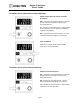
Series III Avionics Pilot's Guide CD-412B Control-Display Page 11
Series III Avionics Pilot's Guide VNS-41A Controls Function Selector and Volume Control OFF - Deactivates the VNS-41A System. Records the last frequencies displayed into the system's non-volatile memory. ON - Activates the VNS-41A System. The last frequencies displayed reappear on the display. RAD - Displays the radial the aircraft is on from the selected VOR. It is displayed digitally below the selected VOR frequency. BRG - Displays the bearing to the selected VOR.
Series III Avionics Pilot's Guide VNS-41A Display When the VNS-41A is turned on, the last display before turnoff is displayed again. The upper line of the display always shows the active frequency (indicated by the letters ACT. The lower display may show the standby frequency, digital radial or bearing, or LOC annunciation, depending on the FUNCTION SELECTOR setting. When two frequencies are displayed, rotating the FREQUENCY knobs changes the bottom (standby) frequency.
Series III Avionics Pilot's Guide When the top (active) frequency is a localizer station, bearing or radial cannot be displayed. Setting the FUNCTION SELECTOR switch to BRG or RAD will cause the letters LOC to appear on the bottom line instead of the standby frequency. This is a reminder that this display cannot be used for bearing or radial data while on an ILS approach. NOTE: When LOC is displayed, return the FUNCTION SELECTOR to the ON position so that the standby frequency is displayed instead.
Series III Avionics Pilot's Guide Operating the VNS-41A 1. Set the FUNCTION SELECTOR to ON. 2. If these are not the desired frequencies, rotate the FREQUENCY KNOBS until the desired frequency is displayed on the bottom portion of the display 3. Press and release the FREQUENCY TRANSFER button. This exchanges the two displayed frequencies. The desired frequency is now active and may be used immediately. 4. Adjust the VOLUME CONTROL for the desired audio level. 5.
Series III Avionics Pilot's Guide VNS-41A Notes 1. The FREQUENCY SELECTOR KNOBS tune the VNS-41A receiver directly. The display is directly controlled by the receiver, so the frequency display shows the actual frequency to which the receiver is tuned. The transceiver may also be tuned by an external ARINC 429 digital data bus. 2. The VOLUME control on the CD-412B control/display does not adjust the volume of the Marker Beacon receiver in the VNS-41A receiver. This volume is preset.
Series III Avionics Pilot's Guide VNS-41A System Block Diagram (Typical) Page 17
Series III Avionics Pilot's Guide TRS-42A ATC Transponder System General Description The Chelton TRS-42A ATC Transponder System is a digital, microprocessor-controlled 325 Watt transponder that allows positive identification in the Air Traffic Control environment. Features include: Dual transmitter output devices Encoding altimeter readout Dual transponder control from a single Control Display Unit.
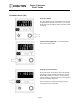
Series III Avionics Pilot's Guide CD-422B Control Display Unit Page 19
Series III Avionics Pilot's Guide TRS-42A Controls Function Selector OFF - Deactivates the TRS-42A System. Records the last data displayed into the system's non-volatile memory. TST - Displays barometric altitude from an encoding altimeter in the lower line of the display. An unsuccessful test displays FAIL in upper line of the display. Pressing the IDENT button in the TST mode causes upper line of the display to read 8888 and lower line to read 88888.
Series III Avionics Pilot's Guide SBY - Applies power to the TRS-42A system circuits without activating the transmitter. The last displayed code appears in the upper line of the display and may be changed with CODE SELECT knobs. Lower line of the display is blank. ON - Enables the TRS-42A to respond to ATC radar interrogations. Altitude is not encoded into the TRS-42A response. ALT - Same as ON except altitude is encoded into the response when the TRS-42A is interrogated by ATC radar.
Series III Avionics Pilot's Guide CODE SELECT Knobs - The outer knob selects the left two digits of the transponder code. the inner knob selects the right two digits. The range for each knob is 00 through 77. When the FUNCTION SELECTOR is in VFR position, the CODE SELECT knobs are disabled because the VFR code (1200 in the U.S.A.) is automatically selected. IDENT Pushbutton - During normal operation, this pushbutton is pressed and released only when ATC requests "squawk ident".
Series III Avionics Pilot's Guide CD-422B Display In normal operation, the upper display is the transponder code. It is selected either by the CODE SELECT knobs or by setting the FUNCTION SELECTOR to VFR. The displayed code is active only when the annunciation ACT is present in the display. When a displayed code is changed, the new code will appear on the display for 3 seconds before the annunciation ACT appears.
Series III Avionics Pilot's Guide If a system failure occurs in any mode, the annunciation FAIL appears in either the upper or lower line of the display. The system is not usable in this condition. Barometric altitude is indicated in lower line of display when the MODE SELECTOR is in TST mode. This is the altitude that will be encoded into the transponder output when operating in an altitude-reporting mode (ALT or VFR positions of FUNCTION SELECTOR).
Series III Avionics Pilot's Guide Operating the TRS-42A Preflight 1. Set the FUNCTION SELECTOR to TST. 2. Select System 1 or System 2 (if more than one transponder system is installed). 3. Note the encoding barometric altitude in lower display. 4. Press the IDENT pushbutton. Note that the numbers 8888 are present in upper line of the display, and that 88888 is displayed in lower line. 5. Set the FUNCTION SELECTOR to SBY. The system is now ready for operation. Flight Operation 1.
Series III Avionics Pilot's Guide TRS-42A Notes 1. Airborne ATC transponders are designed to operate in the Air Traffic Control Radar Beacon System (ATCRBS) environment to support inflight aircraft identification and traffic control. 2. Airborne ATC transponders respond to signals from ATC secondary radar that scans the same volume of airspace as, and in synchronization with, ATC primary radar. The ATC secondary radar operates on 1030 MHz.
Series III Avionics Pilot's Guide TRS-42A System Block Diagram (Typical) Page 27
Series III Avionics Pilot's Guide DFS-43A Automatic Direction Finder System General Description The DFS-43A Direction Finder System provides reception of low-frequency navigational aids and AM broadcast stations in the 190.0 – 1860 kHz frequency range. The DFS-43A System consists of the DF-431B Receiver, the CD-432B Control Display Unit, and the AT434 Loop/Sense Antenna.
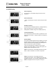
Series III Avionics Pilot's Guide CD-432B Control Display Unit Page 29
Series III Avionics Pilot's Guide DFS-43A Controls Function Selector and Volume Control OFF - Deactivates the DFS-43A System. Records the last frequencies displayed in the system's non-volatile memory. ANT - Enables the DFS-43A System and the non-directional sense antenna. The last frequencies displayed reappear on the display. Frequency tuning is enabled, but no direction-finding capability exists in this mode. External pointers park at 90°. ADF - Standard direction finding mode.
Series III Avionics Pilot's Guide TST - Test Mode 1. Sends a park-at-90° command to external indicators. 2. Displays the letter L along with a number in Standby Frequency window, used for maintenance purposes. 3. Pressing the WHOLE/HALF KHZ button in this mode interrupts the park-at-90° command and provides station relative bearing to external indicators. Simultaneously, the lower line of the display will indicate the same relative bearing digitally to the nearest tenth of a degree.
Series III Avionics Pilot's Guide When the large knob is rotated clockwise from 18 to the next detent, 2100 will appear in the display. Next, rotating the small knob one detent clockwise will cause 2182 to appear in the display. The small knob may then be used to tune from 2181 through 2183 about the maritime emergency frequency of 2182 kHz. WHOLE/HALF KHZ Pushbutton switch. Alternates between one-half kHz tuning and whole (units) tuning by the small FREQUENCY KNOB.
Series III Avionics Pilot's Guide The top line of the display is always the active frequency, indicated by the letters ACT. The number 1 or 2 below the letters ACT indicate the ADF System Number when more than one system is installed. Data in the lower line of the display depends on position of FUNCTION SELECTOR. In ANT, ADF, or BFO mode, the bottom line of the display indicates the standby frequency. In BRG mode, the bottom line of the display indicates the magnetic bearing of active station.
Series III Avionics Pilot's Guide Operating the DFS-43A 1. Set the FUNCTION SELECTOR to ANT. Note that the external ADF pointer moves to 90° and stops. 2. If frequencies displayed are not the ones desired, rotate the FREQUENCY KNOBS until the desired frequency is displayed on the bottom line of the display. 3. Press and release the FREQUENCY TRANSFER button. This exchanges the two displayed frequencies. The desired frequency is now active.
Series III Avionics Pilot's Guide DFS-43A Notes 1. The FREQUENCY SELECTOR knobs tune the DF-431B receiver directly. The display actually shows the frequencies to which the receiver is tuned. In addition to rotation of the FREQUENCY SELECTOR KNOBS, the receiver may be tuned by an external ARINC 429 digital bus. 2. Display intensity and panel lighting are controlled by external dimmer controls. 3.
Series III Avionics Pilot's Guide DFS-43A System Block Diagram (Typical) Page 36
Series III Avionics Pilot's Guide DMS-44A Distance Measuring System General Description The DMS-44A is a digital, solid-state distance measuring system that can provide data from three DME stations simultaneously. A system consists of a DM-441B transceiver and one or two SD-442B Selector-Displays. The transceiver unit may be front or rear antenna connector mounted. An efficient, advanced-design heat sink and cooling fin dissipate internal heat and keep the unit cool even at its full 325 Watt output.
Series III Avionics Pilot's Guide SD-442B Selector Display Unit Page 38
Series III Avionics Pilot's Guide DMS-44A Controls The DMS-44A has only three controls, all located on the SD-442B Selector-Display Unit. Each is a momentary, spring-loaded type that releases when finger pressure is removed. On-off power is through an external switch such as a radio or avionics master switch, or a dedicated DME switch. Volume control of DME station identification audio is also external, typically located on an audio panel. NAV - Alternately places annunciator 1, 2, or RNV in display.
Series III Avionics Pilot's Guide TTS - (Time-To-Station) While this switch is held pressed, time-to-station will be shown on the display above the switch. When the switch is released, the display returns to its previous readout of ground speed. If in hold when the TTS switch is pressed, the HLD FREQ on the display will blink twice to alert the pilot. NOTE: When DME is being tuned by an MLS, receive DME hold is inhibited.
Series III Avionics Pilot's Guide Operating the DMS-44A 1. Apply power to the DMS-44A (depending on installation, the power-on switch may be an avionics master switch, radio switch, or a dedicated DME switch). The SD-442B display(s) will come on immediately, displaying either data, dashes (flag condition) or the word FAIL. 2. Select a NAV Receiver to control the DM-441B by pressing the NAV pushbutton to display a 1, 2, or RNAV. 3.
Series III Avionics Pilot's Guide DMS-44A Notes 1. DME operates within a band of 252 internationally assigned frequency channels from 962 Megahertz to 1213 Megahertz. All channels are not currently in use, but the DMS-44A is tunable to all 252. 2. DME equipment aboard the aircraft measures the delay between interrogation pulses transmitted and reply responses received. This delay is converted to distance, and, as distance changes with time, to ground speed.
Series III Avionics Pilot's Guide DMS-44A System Block Diagram (Typical) Page 43