WORK SHOP MANUAL ENGINE BASE N4.40 (Before serial number KTF08040093) NANNI INDUSTRIES S.A.S – Zone Industrielle 11 avenue MARIOTTE B.P.
TO THE READER This Workshop Manual has been prepared to provide servicing personnel with information on the mechanism, service and maintenance of 03-E2B series. It is divided into three parts, “General”, “Mechanism” and “Servicing”. Q General Information on the engine identification, the general precautions, maintenance check list, check and maintenance and special tools are described. Q Mechanism Information on the construction and function are included.
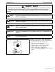
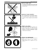
SAFETY INSTRUCTIONS 03-E2B SERIES, WSM SAFETY INSTRUCTIONS SAFETY FIRST This symbol, the industry’s “Safety Alert Symbol”, is used throughout this manual and on labels on the machine itself to warn of the possibility of personal injury. Read these instructions carefully. It is essential that you read the instructions and safety regulations before you attempt to repair or use this unit. DANGER : Indicates an imminently hazardous situation which, if not avoided, will result in death or serious injury.
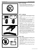
SAFETY INSTRUCTIONS 03-E2B SERIES, WSM SAFETY STARTING • Do not start the engine by shorting across starter terminals or bypassing the safety start switch. • Unauthorized modifications to the engine may impair the function and / or safety and affect engine life. SAFETY WORKING • Do not work on the machine while under the influence of alcohol, medication, or other substances or while fatigued. • Wear close fitting clothing and safety equipment appropriate to the job. • Use tools appropriate to the work.
SAFETY INSTRUCTIONS 03-E2B SERIES, WSM VENTILATE WORK AREA • If the engine must be running to do some work, make sure the area is well ventilated. Never run the engine in a closed area. The exhaust gas contains poisonous carbon monoxide. DISPOSE OF FLUIDS PROPERLY • Do not pour fluids into the ground, down a drain, or into a stream, pond, or lake. Observe relevant environmental protection regulations when disposing of oil, fuel, coolant, electrolyte and other harmful waste.
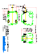
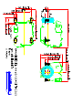
19/02/2009 TECHNICAL DATA ENGINE MODEL N4.40 (up to serial number: KTF08040092) LUBRIFICATION ENGINE SPECIFICATIONS Number of cylinders: 4 Displacement: 1857 cc Bore - Stroke: 80 X 92.4 mm Compression ratio: 23/1 Max. pressure difference between cyl. : 10% Compression pressure: 36 to 38 bars Maximum speed without load: 3050 rpm Maximum speed in load: 2800 rpm Idle speed in forward gear: 850 rpm Max.
GENERAL CONTENTS 1. ENGINE IDENTIFICATION ............................................................................. G-1 [1] MODEL NAME AND ENGINE SERIAL NUMBER ................................ G-1 [2] E2B ENGINE............................................................................................. G-2 [3] CYLINDER NUMBER ............................................................................... G-2 2. GENERAL PRECAUTIONS ........................................................................
G GENERAL 03-E2B SERIES, WSM 1. ENGINE IDENTIFICATION [1] MODEL NAME AND ENGINE SERIAL NUMBER When contacting the manufacture, always specify your engine model name and serial number. The engine model and its serial number need to be identified before the engine can be serviced or parts replaced. Q Engine Serial Number The engine serial number is an identified number for the engine. It is marked after the engine model number. It indicates month and year of manufacture as follows.
G GENERAL 03-E2B SERIES, WSM • Month of manufacture Month Engine Serial Number 0001 ~ 9999 10000 ~ January A0001 ~ A9999 B0001 ~ February C0001 ~ C9999 D0001 ~ March E0001 ~ E9999 F0001 ~ April G0001 ~ G9999 H0001 ~ May J0001 ~ J9999 K0001 ~ June L0001 ~ L9999 M0001 ~ July N0001 ~ N9999 P0001 ~ August Q0001 ~ Q9999 R0001 ~ September S0001 ~ S9999 T0001 ~ October U0001 ~ U9999 V0001 ~ November W0001 ~ W9999 X0001 ~ December Y0001 ~ Y9999 Z0001 ~ e.g.
G GENERAL 03-E2B SERIES, WSM 2. GENERAL PRECAUTIONS • During disassembly, carefully arrange removed parts in a clean area to prevent confusion later. Screws, bolts and nuts should be replaced in their original position to prevent reassembly errors. • When special tools are required, use KUBOTA genuine special tools. Special tools which are not frequently used should be made according to the drawings provided.
G GENERAL 03-E2B SERIES, WSM 3. MAINTENANCE CHECK LIST To maintain long-lasting and safe engine performance, make it a rule to carry out regular inspections by following the table below. Item 50 hrs * Checking fuel hoses and clamp bands Changing engine oil (depending on the oil pan) (1) Oil pan depth (90 mm, 3.54 in.) (2) Oil pan depth (124 mm, 4.88 in.
G GENERAL 03-E2B SERIES, WSM CAUTION • When changing or inspecting, be sure to level and stop the engine. Q NOTE Lubricating Oil With the emission control now in effect, the CF-4 and CG-4 lubricating oils have been developed for use of a lowsulfur fuel on-road vehicle engines. When an off-road vehicle engine runs on a high-sulfur fuel, it is advisable to employ the CF, CD or CE lubricating oil with a high total base number.
G GENERAL 03-E2B SERIES, WSM 4. CHECK AND MAINTENANCE [1] DAILY CHECK POINTS Checking Engine Oil Level 1. Level the engine. 2. To check the oil level, draw out the dipstick (1), wipe it clean, reinsert it, and draw it out again. Check to see that the oil level lies between the two notches. 3. If the level is too low, add new oil to the specified level. Q IMPORTANT • When using an oil of different maker or viscosity from the previous, drain old oil. Never mix two different types of oil.
G GENERAL 03-E2B SERIES, WSM Checking and Replenish Coolant 1. Without recovery tank : Remove the radiator cap (1) and check to see that the coolant level is just below the port. With recovery tank (2) : Check to see that the coolant level lies between FULL (A) and LOW (B). 2. If coolant level is too low, check the reason for decreasing coolant. (Case 1) If coolant is decreasing by evaporation, replenish only fresh, soft water.
G GENERAL 03-E2B SERIES, WSM [2] CHECK POINTS OF INITIAL 50 HOURS Changing Engine Oil • 1. 2. 3. 4. 5. Q • • • • CAUTION Be sure to stop engine before changing engine oil. Start and warm up the engine for approx. 5 minutes. Place an oil pan underneath the engine. To drain the used oil, remove the drain plug (1) at the bottom of the engine and drain the oil completely. Screw the drain plug (1). Fill new oil up to upper line on the dipstick (2).
G GENERAL 03-E2B SERIES, WSM Replacing Oil Filter Cartridge • 1. 2. 3. 4. Q • CAUTION Be sure to stop the engine before replacing filter cartridge. Remove the oil filter cartridge (1) with the filter wrench. Apply a slight coat of oil onto the new cartridge gasket. To install the new cartridge, screw it in by hand. Over tightening may cause deformation of rubber gasket. After the new cartridge has been replaced, the engine oil normally decrease a little.
G GENERAL 03-E2B SERIES, WSM [3] CHECK POINTS OF EVERY 50 HOURS Checking Fuel Hoses and Clamp Bands 1. If the clamp (2) is loose, apply oil to the threads and securely retighten it. 2. The fuel hose (1) is made of rubber and ages regardless of the period service. Change the fuel hose together with the clamp every two years. 3. However, if the fuel hose and clamp are found to be damaged or deteriorate earlier than two years, then change or remedy. 4.
G GENERAL 03-E2B SERIES, WSM [4] CHECK POINTS OF EVERY 100 HOURS Cleaning Air Cleaner Element 1. Remove the air cleaner element. 2. Use clean dry compressed air on the inside of the element. Pressure of compressed air must be under 205 kPa (2.1 kgf/cm2, 30 psi). Maintain reasonable distance between the nozzle and the filter. Q NOTE • The air cleaner uses a dry element. Never apply oil to it. • Do not run the engine with filter element removed. • Change the element once a year or every 6th cleaning.
G GENERAL 03-E2B SERIES, WSM Fan Belt Damage and Wear 1. Check the fan belt for damage. 2. If the fan belt is damaged, replace it. 3. Check if the fan belt is worn and sunk in the pulley groove. 4. If the fan belt is nearly worn out and deeply sunk in the pulley groove, replace it.
G GENERAL 03-E2B SERIES, WSM [5] CHECK POINTS OF EVERY 150 HOURS Changing Engine Oil (for 90 mm (3.54 in.) Depth Oil Pan) • 1. 2. 3. 4. 5. Q • • • • CAUTION Be sure to stop engine before changing engine oil. Start and warm up the engine for approx. 5 minutes. Place an oil pan underneath the engine. To drain the used oil, remove the drain plug (1) at the bottom of the engine and drain the oil completely. Screw the drain plug (1). Fill new oil up to upper line on the dipstick (2).
G GENERAL 03-E2B SERIES, WSM Replacing Oil Filter Cartridge (for 90 mm (3.54 in.) Depth Oil Pan) • 1. 2. 3. 4. Q • CAUTION Be sure to stop the engine before replacing filter cartridge. Remove the oil filter cartridge (1) with the filter wrench. Apply a slight coat of oil onto the new cartridge gasket. To install the new cartridge, screw it in by hand. Over tightening may cause deformation of rubber gasket. After the new cartridge has been replaced, the engine oil normally decrease a little.
G GENERAL 03-E2B SERIES, WSM [6] CHECK POINTS OF EVERY 200 HOURS Changing Engine Oil (for 124 mm (4.88 in.) Depth Oil Pan) • 1. 2. 3. 4. 5. Q • • • • CAUTION Be sure to stop engine before changing engine oil. Start and warm up the engine for approx. 5 minutes. Place an oil pan underneath the engine. To drain the used oil, remove the drain plug (1) at the bottom of the engine and drain the oil completely. Screw the drain plug (1). Fill new oil up to upper line on the dipstick (2).
G GENERAL 03-E2B SERIES, WSM Replacing Oil Filter Cartridge (for 124 mm (4.88 in.) Depth Oil Pan) • 1. 2. 3. 4. Q • CAUTION Be sure to stop the engine before replacing filter cartridge. Remove the oil filter cartridge (1) with the filter wrench. Apply a slight coat of oil onto the new cartridge gasket. To install the new cartridge, screw it in by hand. Over tightening may cause deformation of rubber gasket. After the new cartridge has been replaced, the engine oil normally decrease a little.
G GENERAL 03-E2B SERIES, WSM [7] CHECK POINTS OF EVERY 400 HOURS Replacing Fuel Filter Cartridge (Cartridge Type) Water and dust in fuel are collected in the filter cartridge. So, change the filter cartridge every 400 hours service. 1. Remove the used filter cartridge with filter wrench. 2. Apply a thin film of fuel to the surface of new filter cartridge gasket before screwing on. 3. Then tighten enough by hand. 4. Loosen the air vent plug to let the air out. 5. Start engine and check for fuel leakage.
G GENERAL 03-E2B SERIES, WSM [8] CHECK POINTS OF EVERY 500 HOURS Cleaning Water Jacket and Radiator Interior CAUTION • Do not remove the radiator cap when the engine is hot. Then loosen cap slightly to the stop to relieve any excess pressure before removing cap completely. 1. Stop the engine and let cool down. 2. To drain the coolant, open the radiator drain plug (2) and remove the radiator cap (1). Then radiator cap (1) must be removed to completely drain the coolant. And open the drain cock (3). 3.
G GENERAL 03-E2B SERIES, WSM Anti-Freeze • There are two types of anti-freeze available: use the permanent type (PT) for this engine. • Before adding anti-freeze for the first time, clean the radiator interior by pouring fresh, soft water and draining it a few times. • The procedure for mixing water and anti-freeze differs according to the make of the anti-freeze and the ambient temperature. Basically, it should be referred to SAE J1034 standard, more specifically also to SAE J814c.
G GENERAL 03-E2B SERIES, WSM [9] CHECK POINTS OF EVERY 1 OR 2 MONTHS Recharging CAUTION • When the battery is being activated, hydrogen and oxygen gases in the battery are extremely explosive. Keep open sparks and flames away from the battery at all times, especially when charging the battery. • When charging battery, remove battery vent plugs. • When disconnecting the cable from the battery, start with the negative terminal first.
G GENERAL 03-E2B SERIES, WSM Battery Specific Gravity 1. Check the specific gravity of the electrolyte in each cell with a hydrometer. 2. When the electrolyte temperature differs from that at which the hydrometer was calibrated, correct the specific gravity reading following the formula mentioned in (Reference). 3. If the specific gravity is less than 1.215 (after it is corrected for temperature), charge or replace the battery. 4. If the specific gravity differs between any two cells by more than 0.
G GENERAL 03-E2B SERIES, WSM [11] CHECK POINTS OF EVERY 800 HOURS Valve Clearance Q IMPORTANT • Valve clearance must be checked and adjusted when engine is cold. 1. Remove the head cover. 2. Align the “1TC” mark line (3) on the flywheel and projection (2) on the housing so that the No.1 piston comes to the compression or overlap top dead center. 3. Check the following valve clearance (1) marked with “,” using a feeler gauge. 4.
G GENERAL 03-E2B SERIES, WSM [12] CHECK POINTS OF EVERY 1500 HOURS CAUTION • Check the injection pressure and condition after confirming that there is nobody standing in the direction the fume goes. • If the fume from the nozzle directly contacts the human body, cells may be destroyed and blood poisoning may be caused. Nozzle Spraying Condition 1. Set the injection nozzle to a nozzle tester, and check the nozzle spraying condition. 2. If the spraying condition is defective, replace the nozzle piece.
G GENERAL 03-E2B SERIES, WSM Nozzle Holder 1. Secure the nozzle retaining nut (7) with a vise. 2. Remove the nozzle holder (1), and take out parts inside. (When reassembling) • Assemble the nozzle in clean fuel oil. • Install the push rod (4), noting its direction. • After assembling the nozzle, be sure to adjust the fuel injection pressure. Tightening torque (1) (2) (3) (4) Nozzle Holder Adjusting Washer Nozzle Spring Push Rod Nozzle holder 34.3 to 39.2 N·m 3.5 to 4.0 kgf·m 25.3 to 28.
G GENERAL 03-E2B SERIES, WSM [13] CHECK POINTS OF EVERY 3000 HOURS Checking Turbocharger (Turbine Side) 1. Check the exhaust port (2) and inlet port (3) side of turbine housing (1) to see if there is no exhaust gas leak. 2. If any gas leak is found, retighten the bolts and nuts or replace the gasket with new one. (Compressor Side) 1. Check the inlet hose (4) of the compressor cover (5) to see if there is no air leak. 2. Check for loose connections or cracks in the suction side of the intake hose. 3.
G GENERAL 03-E2B SERIES, WSM Injection Timing 1. Remove the injection pipes and nozzle. 2. Set the speed control lever to maximum fuel discharge position. (Reference) • Turn the flywheel with screwdriver. 3. Turn the flywheel counterclockwise (facing the flywheel) until the fuel fills up to the hole of the delivery valve holder for 1st cylinder. 4. Turn the flywheel further and stop turning when the fuel begins to flow over, to get the present injection timing. 5.
G GENERAL 03-E2B SERIES, WSM Checking Injection Pump (Fuel Tightness of Pump Element) 1. Remove the engine stop solenoid. 2. Remove the injection pipes and glow plugs. 3. Install the injection pump pressure tester to the injection pump. 4. Install the injection nozzle (2) jetted with the proper injection pressure to the injection pump pressure tester (1). (Refer to the figure.) 5. Set the speed control lever to the maximum speed position. 6. Run the starter to increase the pressure. 7.
G GENERAL 03-E2B SERIES, WSM [14] CHECK POINTS OF EVERY 2 YEARS Replacing Intake Air Line 1. Loosen the clamp (2). 2. Remove the intake air hose (1) and clamp (2). 3. Replace new intake air hose (1) and new clamp (2). 4. Tighten the clamp (2). Q NOTE • To prevent serious damage to the engine, keep out any dust inside the intake air line.
G GENERAL 03-E2B SERIES, WSM Replacing Fuel Hoses and Clamp Bands 1. Loosen the clamp (2) and remove the fuel hose (1). 2. Replace new fuel hose (1) and new clamp (2). 3. Tighten the clamp (2). CAUTION • Stop the engine when attempting the check and change prescribed above. (When bleeding fuel system) 1. Fill the tank with fuel and open the cock (4). 2. Loosen the air vent plug (3) of the fuel filter a few turns. 3. Screw back the plug when bubbles do not come up any more. 4.
G GENERAL 03-E2B SERIES, WSM Changing Radiator Coolant (L.L.C.) • 1. 2. 3. 4. 5. 6. 7. 8. 9. Q • • • • (1) (2) (3) (4) CAUTION Do not remove the radiator cap when the engine is hot. Then loosen cap slightly to the stop to relieve any excess pressure before removing cap completely. Stop the engine and let cool down. To drain the coolant, open the radiator drain plug (2) and remove the radiator cap (1). Then radiator cap (1) must be removed to completely drain the coolant. And open the drain cock (3).
G GENERAL 03-E2B SERIES, WSM Changing Radiator Coolant (L.L.C.) (Continued) (Anti-freeze) • There are two types of anti-freeze available: use the permanent type (PT) for this engine. • Before adding anti-freeze for the first time, clean the radiator interior by pouring fresh, soft water and draining it a few times. • The procedure for mixing water and anti-freeze differs according to the make of the anti-freeze and the ambient temperature.
G GENERAL 03-E2B SERIES, WSM 5. SPECIAL TOOLS Diesel Engine Compression Tester Code No: 07909-30208 (Assembly) 07909-31251 (G) 07909-30934 (A to F) 07909-31271 (I) 07909-31211 (E and F) 07909-31281 (J) 07909-31231 (H) Application: Use to measure diesel engine compression and diagnosis of need for major overhaul.
G GENERAL 03-E2B SERIES, WSM Q NOTE • The following special tools are not provided, so make them referring to the figure. Injection Pump Pressure Tester Application: Use to check fuel tightness of injection pumps. A Pressure gauge full scale : More than 29.4 MPa (300 kgf/cm2, 4267 psi) B PF 1/2 C Copper gasket D Flange (Material : Steel) E Hex. nut 27 mm (1.06 in.) across the plat F Adhesive application G Fillet welding on the enter circumference H Retaining nut I 17 mm dia. (0.67 in.
G GENERAL 03-E2B SERIES, WSM Bushing Replacing Tools Application: Use to press out and to press in the bushing. 1. For small end bushing A 162 mm (6.38 in.) B 35 mm (1.38 in.) C 27 mm (1.06 in.) D 35 mm dia. (1.38 in. dia.) E 27.90 to 27.95 mm dia. (1.098 to 1.100 in. dia.) F 25.00 to 25.01 mm dia. (0.984 to 0.985 in. dia.) 2. For idle gear bushing A 175 mm (6.89 in.) B 40 mm (1.57 in.) C 38 mm (1.50 in.) D 45 mm dia. (1.77 in. dia.) E 41.90 to 41.95 mm dia. (1.650 to 1.652 in. dia.
G GENERAL 03-E2B SERIES, WSM Crankshaft Bearing 1 Replacing Tool (D1403/D1503/D1703/V1903/V2003-T/V2203-E2B) Application: Use to press out and press in the crankshaft bearing 1. 1. Extracting tool A 135 mm (5.31 in.) B 72 mm (2.83 in.) C 40 mm radius (1.57 in. radius) D 10 mm (0.39 in.) E 20 mm (0.79 in.) F 20 mm dia. (0.79 in. dia.) G 64.8 to 64.9 mm dia. (2.551 to 2.555 in. dia.) H 59.8 to 59.9 mm dia. (2.354 to 2.358 in. dia.) 2. Inserting tool A 130 mm (5.12 in.) B 72 mm (2.83 in.
G GENERAL 03-E2B SERIES, WSM Auxiliary Socket for Fixing Crankshaft Sleeve Application: Use to fix the crankshaft sleeve of the diesel engine. A B 80.0 mm (3.1496 in.) F2803-E2B 52.1 to 52.3 mm (2.0512 to 2.0591 in.) D1403-E2B D1503-E2B D1703-E2B V1903-E2B V2003-TE2B V2203-E2B 60.1 to 60.3 mm (2.3661 to 2.3740 in.) C 80.0 mm dia. (3.1496 in. dia.) D 85.0 mm dia. (3.3465 in. dia.) E F2803-E2B 52.1 to 52.3 mm dia. (2.0512 to 2.0591 in. dia.
G GENERAL 03-E2B SERIES, WSM Auxiliary Socket for Fixing Crankshaft Sleeve (Continued) Application: Use to fix the crankshaft sleeve of the diesel engine. J 42.0 mm (1.6535 in.) K 30.5 to 30.6 mm (1.2008 to 1.2047 in.) L 23.0 mm (0.9055 in.) M 20.0 mm (0.7874 in.) N 2.0 mm (0.0787 in.) O 31.911 to 31.950 mm dia. (1.2563 to 1.2579 in. dia.) P 30.0 mm dia. (1.1811 in. dia.) Q 5.0 mm dia. (0.1969 in. dia.) R 0.087 rad (5 °) S 25.0 mm dia. (0.9843 in. dia.) T 60.0 mm dia. (2.3622 in. dia.
MECHANISM CONTENTS 1. ENGINE BODY ............................................................................................... M-1 [1] HALF-FLOATING HEAD COVER ............................................................ M-1 [2] CLOSED BREATHER (D1403 / D1503 / D1703 / V1903 / V2203-E2B) .. M-1 2. FUEL SYSTEM ............................................................................................... M-2 [1] GOVERNOR .....................................................................................
DIESEL ENGINE 03-E2B SERIES, WSM 1. ENGINE BODY [1] HALF-FLOATING HEAD COVER The rubber packing is fitted in to maintain the cylinder head cover 0.5 mm (0.02 in.) or so off the cylinder head. This arrangement helps reduce noise coming from the cylinder head. (1) Cylinder Head Cover (2) Rubber Packing [2] CLOSED BREATHER (D1403 / D1503 / D1703 / V1903 / V2203-E2B) Closed breather system has been adopted to prevent the release of blow-by gas into the atmosphere.
DIESEL ENGINE 03-E2B SERIES, WSM 2. FUEL SYSTEM [1] GOVERNOR The governor serves to keep engine speed constant by automatically adjusting the amount of fuel supplied to the engine according to changes in the load. This engine employs an all-speed governor which controls the centrifugal force of the steel ball (1) weight, produced by rotation of the fuel camshaft (5), and the tension of the governor spring 1 (7) and 2 (8) are balanced.
SERVICING CONTENTS 1. TROUBLESHOOTING ......................................................................................S-1 2. SERVICING SPECIFICATIONS ......................................................................S-5 3. TIGHTENING TORQUES ..............................................................................S-13 [1] TIGHTENING TORQUES FOR GENERAL USE SCREWS, BOLTS AND NUTS...............................................................................................
DIESEL ENGINE 03-E2B SERIES, WSM 1.
DIESEL ENGINE 03-E2B SERIES, WSM Symptom Engine Revolution Is Not Smooth Probable Cause Solution Reference Page Fuel filter clogged or dirty Replace G-10, 17 Air cleaner clogged Clean or replace G-11, 16, 21 Fuel leak due to loose injection pipe retaining nut Tighten retaining nut Injection pump malfunctioning Repair or replace S-21, 35 Incorrect nozzle opening pressure Repair or replace S-22 Injection nozzle stuck or clogged Repair or replace S-22, 23 Governor malfunctioning Repair
DIESEL ENGINE 03-E2B SERIES, WSM Symptom Deficient Output Probable Cause Reference Page Solution Incorrect injection timing Adjust Engine’s moving parts seem to be seizing Repair or replace – Injection pump malfunctioning Repair or replace S-21, 35 Deficient nozzle injection Repair or replace nozzle S-22, 23 Compression leak Check the compression pressure and repair Gas leak from exhaust system Repair or replace S-27, 29 Air leak from compressor discharge side Repair or replace S-27,
DIESEL ENGINE 03-E2B SERIES, WSM Symptom High Oil Pressure Engine overheated Battery Quickly Discharged Probable Cause Solution Reference Page Different type of oil Use specified type of oil G-8 Relief valve defective Replace Engine oil insufficient Replenish Fan belt broken or elongated Replace or adjust Coolant insufficient Replenish Radiator net and radiator fin clogged with dust Clean Inside of radiator corroded Clean or replace G-18 Coolant flow route corroded Clean or replace
DIESEL ENGINE 03-E2B SERIES, WSM 2. SERVICING SPECIFICATIONS ENGINE BODY Item Valve Clearance (When Cold) Compression Pressure (When Cranking with Starting Motor) Difference among Cylinders Top Clearance Factory Specification Allowable Limit 0.18 to 0.22 mm 0.0071 to 0.0087 in. – 3.53 to 3.72 MPa / 290 min-1 (rpm) 36 to 38 kgf/cm2 / 290 min-1 (rpm) 512 to 540 psi / 290 min-1 (rpm) 2.55 MPa / 290 min-1 (rpm) 26 kgf/cm2 / 290 min-1 (rpm) 370 psi / 290 min-1 (rpm) – 10 % or less 0.55 to 0.70 mm 0.
DIESEL ENGINE 03-E2B SERIES, WSM ENGINE BODY (Continued) Item Factory Specification Allowable Limit Open 0.14 rad (8 °) before T.D.C. – Close 0.35 rad (20 °) after B.D.C. – Valve Timing (Intake Valve) [D1703-E2B] [V1903-E2B] [V2203-E2B] [F2803-E2B] Open 0.21 rad (12 °) before T.D.C. – Close 0.63 rad (36 °) after B.D.C. – Valve Timing (Intake Valve) [V2003-TE2B] Open 0.35 rad (20 °) before T.D.C. – Close 0.79 rad (45 °) after B.D.C. – Open 1.05 rad (60 °) before B.D.C. – Close 0.
DIESEL ENGINE 03-E2B SERIES, WSM ENGINE BODY (Continued) Item Factory Specification Allowable Limit Oil Clearance 0.020 to 0.062 mm 0.00079 to 0.00244 in. 0.07 mm 0.0028 in. Tappet O.D. 23.959 to 23.980 mm 0.94327 to 0.94410 in. – Tappet Guide I.D. 24.000 to 24.021 mm 0.94488 to 0.94571 in. – Timing Gear Crank Gear to Idle Gear Backlash 0.0415 to 0.1122 mm 0.00163 to 0.00442 in. 0.15 mm 0.0059 in. Idle Gear to Cam Gear Backlash 0.0415 to 0.1154 mm 0.00163 to 0.00454 in. 0.15 mm 0.
DIESEL ENGINE 03-E2B SERIES, WSM ENGINE BODY (Continued) Item Factory Specification Allowable Limit Oil Clearance 0.050 to 0.091 mm 0.00197 to 0.00358 in. 0.15 mm 0.0059 in. Camshaft Journal O.D. 39.934 to 39.950 mm 1.57221 to 1.57284 in. – Cylinder Block Bore I.D. 40.000 to 40.025 mm 1.57480 to 1.57579 in. – Piston Pin Bore I.D. 25.000 to 25.013 mm 0.98425 to 0.98476 in. 25.05 mm 0.9862 in. Second Ring to Ring Groove [D1403/D1503/D1703/V1903/V2203/ F2803-E2B] Clearance 0.093 to 0.
DIESEL ENGINE 03-E2B SERIES, WSM ENGINE BODY (Continued) Item Crankshaft Journal to Crankshaft Bearing 1 Oil Clearance [D1403/D1503/D1703/V1903/V2003-T/ V2203-E2B] Factory Specification Allowable Limit 0.040 to 0.118 mm 0.00157 to 0.00465 in. 0.20 mm 0.0079 in. Crankshaft Journal O.D. 59.921 to 59.940 mm 2.35910 to 2.35984 in. – Crankshaft Bearing 1 I.D. 59.980 to 60.039 mm 2.36142 to 2.36374 in. – 0.040 to 0.118 mm 0.00157 to 0.00465 in. 0.20 mm 0.0079 in.
DIESEL ENGINE 03-E2B SERIES, WSM ENGINE BODY (Continued) Item Factory Specification Allowable Limit Crankshaft [D1403/D1503/D1703/V1903/V2003-T/ V2203-E2B] Side Clearance 0.15 to 0.31 mm 0.0059 to 0.0122 in. 0.50 mm 0.0197 in. Crankshaft [F2803-E2B] Side Clearance 0.15 to 0.35 mm 0.0059 to 0.0138 in. 0.50 mm 0.0197 in. Cylinder Bore (Standard) [D1403-E2B] [V1903-E2B] I.D. 80.000 to 80.022 mm 3.14961 to 3.15047 in. 80.150 mm 3.15551 in. Cylinder Bore (Standard) [D1503-E2B] [V2003-TE2B] I.D.
DIESEL ENGINE 03-E2B SERIES, WSM COOLING SYSTEM Item Factory Specification Allowable Limit 7.0 to 9.0 mm (0.28 to 0.35 in.) deflection at 98 N (10 kgf, 22 lbs) of force – Fan Belt Tension Thermostat Valve Opening Temperature (At Beginning) 69.5 to 72.5 °C 157.1 to 162.5 °F – Valve Opening Temperature (Opened Completely) 85 °C 185 °F – Radiator Water Tightness No leak at 137 kPa 1.
DIESEL ENGINE 03-E2B SERIES, WSM ELECTRICAL SYSTEM Item Starter Commutator O.D. Mica Under Cut Brush Length Alternator No-load voltage Factory Specification Allowable Limit 30.0 mm 1.181 in. 29.0 mm 1.142 in. 0.45 to 0.75 mm 0.0177 to 0.0295 in. 0.20 mm 0.0079 in. 15.0 mm 0.591 in. 11.0 mm 0.433 in. More than 13.5 V – Stator Resistance Less than 1.0 Ω – Rotor Resistance 2.9 Ω – Slip Ring O.D. 14.4 mm 0.567 in. 14.0 mm 0.551 in. Brush Length 10.5 mm 0.413 in. 8.4 mm 0.
DIESEL ENGINE 03-E2B SERIES, WSM 3. TIGHTENING TORQUES Screws, bolts and nuts must be tightened to the specified torque using a torque wrench, several screws, bolts and nuts such as those used on the cylinder head must be tightened in proper sequence and the proper torque. [1] TIGHTENING TORQUES FOR GENERAL USE SCREWS, BOLTS AND NUTS When the tightening torques are not specified, tighten the screws, bolts and nuts according to the table below.
DIESEL ENGINE 03-E2B SERIES, WSM [2] TIGHTENING TORQUES FOR SPECIAL USE SCREWS, BOLTS AND NUTS Q NOTE • For “*” marked screws, bolts and nuts on the table, apply engine oil to their threads and seats before tightening. • The letter “M” in Size x Pitch means that the screw, bolt or nut dimension stands for metric. The size is the nominal outside diameter in mm of the threads. The pitch is the nominal distance in mm between two threads.
DIESEL ENGINE 03-E2B SERIES, WSM 4. CHECKING, DISASSEMBLING AND SERVICING [1] CHECKING AND ADJUSTING (1) Engine Body Compression Pressure 1. Run the engine until it is warmed up. 2. Stop the engine and disconnect the 2P connector from the stop solenoid in order not to inject fuel. 3. Remove the air cleaner, the muffler and all injection nozzles. 4. Set a compression tester (Code No. 07909-30208) with the adaptor to the nozzle hole. 5. Keep the engine stop lever at “Stop Position”. 6.
DIESEL ENGINE 03-E2B SERIES, WSM Valve Clearance Q IMPORTANT • Valve clearance must be checked and adjusted when engine is cold. 1. Remove the head cover. 2. Align the “1TC” mark line (3) on the flywheel and projection (2) on the housing so that the No.1 piston comes to the compression or overlap top dead center. 3. Check the following valve clearance (1) marked with “,” using a feeler gauge. 4. If the clearance is not within the factory specifications, adjust with the adjusting screw. Valve clearance 0.
DIESEL ENGINE 03-E2B SERIES, WSM (2) Lubricating System Engine Oil Pressure 1. Remove the engine oil pressure switch, and set an oil pressure tester (Code No.: 07916-32032). (Adaptor screw size : PT 1/8) 2. Start the engine. After warming up, measure the oil pressure of both idling and rated speeds. 3. If the oil pressure is less than the allowable limit, check the following. • Engine oil insufficient.
DIESEL ENGINE 03-E2B SERIES, WSM Fan Belt Damage and Wear 1. Check the fan belt for damage. 2. If the fan belt is damaged, replace it. 3. Check if the fan belt is worn and sunk in the pulley groove. 4. If the fan belt is nearly worn out and deeply sunk in the pulley groove, replace it. (A) Good (B) Bad W1020602 CAUTION • When removing the radiator cap, wait at least ten minutes after the engine has stopped and cooled down. Otherwise, hot water may gush out, scalding nearby people.
DIESEL ENGINE 03-E2B SERIES, WSM Thermostat Valve Opening Temperature 1. Suspend the thermostat in the water by a string with its end inserted between the valve and seat. 2. Heating the water gradually, read the temperature when the valve opens and leaves the string. 3. Continue heating and read the temperature when the valve opens approx. 6 mm (0.236 in.). 4. If the measurement is not within the factory specifications, replace the thermostat. Thermostat’s valve opening temperature Factory spec. 69.
DIESEL ENGINE 03-E2B SERIES, WSM (4) Fuel System Injection Timing 1. Remove the injection pipes and nozzle. 2. Set the speed control lever to maximum fuel discharge position. (Reference) • Turn the flywheel with screwdriver. 3. Turn the flywheel counterclockwise (facing the flywheel) until the fuel fills up to the hole of the delivery valve holder for 1st cylinder. 4. Turn the flywheel further and stop turning when the fuel begins to flow over, to get the present injection timing. 5.
DIESEL ENGINE 03-E2B SERIES, WSM Fuel Tightness of Pump Element 1. Remove the engine stop solenoid. 2. Remove the injection pipes and glow plugs. 3. Install the injection pump pressure tester to the injection pump. 4. Install the injection nozzle (2) jetted with the proper injection pressure to the injection pump pressure tester (1). (Refer to the figure.) 5. Set the speed control lever to the maximum speed position. 6. Run the starter to increase the pressure. 7.
DIESEL ENGINE 03-E2B SERIES, WSM CAUTION • Check the nozzle injection pressure and condition after confirming that there is nobody standing in the direction the fume goes. • If the fume from the nozzle directly contacts the human body, cells may be destroyed and blood poisoning may be caused. Nozzle Spraying Condition 1. Set the injection nozzle to a nozzle tester, and check the nozzle spraying condition. 2. If the spraying condition is defective, replace the nozzle piece.
DIESEL ENGINE 03-E2B SERIES, WSM Nozzle Holder 1. Secure the nozzle retaining nut (7) with a vise. 2. Remove the nozzle holder (1), and take out parts inside. (When reassembling) • Assemble the nozzle in clean fuel oil. • Install the push rod (4), noting its direction. • After assembling the nozzle, be sure to adjust the fuel injection pressure. Tightening torque (1) (2) (3) (4) Nozzle Holder Adjusting Washer Nozzle Spring Push Rod Nozzle holder 34.3 to 39.2 N·m 3.5 to 4.0 kgf·m 25.3 to 28.
DIESEL ENGINE 03-E2B SERIES, WSM Battery Specific Gravity 1. Check the specific gravity of the electrolyte in each cell with a hydrometer. 2. When the electrolyte temperature differs from that at which the hydrometer was calibrated, correct the specific gravity reading following the formula mentioned in (Reference). 3. If the specific gravity is less than 1.215 (after it is corrected for temperature), charge or replace the battery. 4. If the specific gravity differs between any two cells by more than 0.
DIESEL ENGINE 03-E2B SERIES, WSM Motor Test • 1. 2. 3. 4. 5. 6. 7. Q • • CAUTION Secure the starter to prevent it from jumping up and down while testing the motor. Disconnect the battery negative cable from the battery. Disconnect the battery positive cable from the battery. Disconnect the leads from the starter B terminal. Remove the starter from the engine. Connect a jumper lead from the starter C terminal (1) to the battery positive terminal (2).
DIESEL ENGINE 03-E2B SERIES, WSM Alternator on Unit Test (Before testing) • Before alternator on unit test, check the battery terminal connections, circuit connection, fan belt tension, charging indicator lamp, fuses on the circuit, and abnormal noise from the alternator. • Prepare full charged battery for the test. Q NOTE • Be careful not to touch the rotating engine parts while engine is running. Keep safety distance from the engine rotating parts. 1. Start the engine. 2.
DIESEL ENGINE 03-E2B SERIES, WSM (6) Turbocharger Turbine Side 1. Check the exhaust port (2) and inlet port (3) side of the turbine housing (1) to see if there is no exhaust gas leak. 2. If any gas leak is found, retighten the bolts and nuts or replace the gasket with new one. (1) Turbine Housing (2) Exhaust Port (3) Inlet Port W1069824 Compressor Side 1. Check the inlet hose (1) of the compressor cover (2) to see if there is no air leak. 2.
DIESEL ENGINE 03-E2B SERIES, WSM [2] DISASSEMBLING AND ASSEMBLING (1) Draining Oil and Coolant Draining Engine Oil 1. Start and warm up the engine for approx. 5 minutes. 2. Place an oil pan underneath the engine. 3. Remove the drain plug (1) to drain oil. 4. After draining, screw in the drain plug. (When refilling) • Fill the engine oil up to the upper line on the dipstick (2). Q IMPORTANT • Never mix two different types of oil. • Use the proper SAE Engine Oil according to ambient temperature.
DIESEL ENGINE 03-E2B SERIES, WSM Turbocharger (equipped with Turbocharger Model) CAUTION • While the engine is running and or just after it stops, the turbocharger is hot, be careful not to touch the turbocharger. Q NOTE • When detaching and attaching the turbocharger assembly, be very careful not to allow dust, dirt and other foreign matters in the oil pipes. • When the turbocharger assembly has been replaced, pour fresh engine oil through the oil filter port of the turbocharger.
DIESEL ENGINE 03-E2B SERIES, WSM (3) Cylinder Head and Valves Cylinder Head Cover 1. Remove the lead (1). 2. Remove the breather hose (2). 3. [a] D1403/D1503/D1703/V1903/V2203-E2B Remove the cylinder head cover screws (3). [b] V2003-TE2B / [c] F2803-E2B Remove the cylinder head cover cap nuts (8). 4. Remove the cylinder head cover (4). (When reassembling) • Check to see if the cylinder head cover gasket is not defective. Cylinder head cover screw 6.9 to 11.3 N·m 0.7 to 1.15 kgf·m 5.1 to 8.
DIESEL ENGINE 03-E2B SERIES, WSM Injection Pipes 1. Loosen the screws on the pipe clamps (1). 2. Detach the injection pipes (2). (When reassembling) • Blow out dust inside the pipes. Tightening torque Injection pipe retaining nut (1) Pipe Clamp 24.5 to 34.3 N·m 2.5 to 3.5 kgf·m 18.1 to 25.3 ft-lbs (2) Injection Pipe W1060970 Nozzle Holder Assembly and Glow Plug 1. Remove the overflow pipe assembly (3). 2. Remove the nozzle holder assemblies (4) using a 21 mm deep socket wrench. 3.
DIESEL ENGINE 03-E2B SERIES, WSM Rocker Arm and Push Rod 1. Remove the rocker arm bracket screws (D1403/D1503/D1703/ D1903/V2203-E2B) or nuts (V2203-T/F2803-E2B). 2. Detach the rocker arm assembly (1). 3. Remove the push rods (2). (When reassembling) • When putting the push rods (2) onto the tappets (3), check to see if their ends are properly engaged with the grooves. Q IMPORTANT • After installing the rocker arm, be sure to adjust the valve clearance. Rocker arm bracket screw 23.5 to 27.5 N·m 2.4 to 2.
DIESEL ENGINE 03-E2B SERIES, WSM Cylinder Head 1. Loosen the pipe clamp (2), and remove the water return pipe (1). 2. Remove the cylinder head screw in the order of (v or r or n) to (a). 3. Lift up the cylinder head (3) to detach. 4. Remove the cylinder head gasket (4) and O-ring (5). (When reassembling) • Replace the cylinder head gasket (4) with a new one. • Securely fit the O-ring (5) to the pin pipe (6). • Tighten the cylinder head screws after applying sufficient oil.
DIESEL ENGINE 03-E2B SERIES, WSM Thermostat Assembly 1. Remove the thermostat cover mounting screws, and remove the thermostat cover (1). 2. Remove the thermostat assembly (3). (When reassembling) • Apply a liquid gasket (Three Bond 1215 or equivalent) only at the thermostat cover side of the thermostat cover gasket (2). (1) Thermostat Cover (2) Thermostat Cover Gasket (3) Thermostat Assembly W10363950 Tappets 1. Remove the tappets (1) from the crankcase.
DIESEL ENGINE 03-E2B SERIES, WSM (4) Gear Case and Timing Gears Injection Pump 1. Remove the injection pump cover (3) with the engine stop lever (2). 2. Remove the injection pump mounting screws and nuts. 3. Align the control rack pin (4) with the groove (5) on the crankcase, then remove the injection pump. 4. Remove the injection pump timing shims (6). 5. In principle, the injection pump should not be disassemble.
DIESEL ENGINE 03-E2B SERIES, WSM Speed Control Plate 1. Remove the speed control plate and governor spring 1 (2) and 2 (1). (When reassembling) • Be careful not to drop the governor spring in the gear case. • Apply a liquid gasket (Three Bond 1215 or equivalent) to both sides of the speed control plate gasket. (1) Governor Spring 2 (2) Governor Spring 1 W1025063 Start Spring 1. Remove the start spring (1) from the gear case.
DIESEL ENGINE 03-E2B SERIES, WSM Fan Drive Pulley 1. Lock the flywheel not to turn using the flywheel stopper. 2. [D1403/D1503/D1703/V1903/V2003-T/V2203-E2B] Remove the fan drive pulley mounting nut (1) using 46 mm deep socket wrench (5). [F2803-E2B] Remove the fan drive pulley screws. 3. Remove the fan drive pulley (2) with gear puller (3). 4. [D1403/D1503/D1703/V1903/V2003-T/V2203-E2B] Remove the feather key. (When reassembling) • Apply grease to the splines of coupling.
DIESEL ENGINE 03-E2B SERIES, WSM Gear Case 1. Remove the hour meter gear case (if equipped). 2. Remove the gear case (1). 3. Remove the O-rings (2). (When reassembling) • Apply liquid gasket (Three Bond 1215 or equivalent) to both side of hour meter gear case gasket. • Check to see if there are four O-rings (2) inside the gear case (1). • Apply a thin film of engine oil to the oil seal (3), and install it, noting the lip come off. • Before installing the gear case gasket, apply a non-drying adhesive.
DIESEL ENGINE 03-E2B SERIES, WSM Fuel Camshaft and Fork Lever Assembly 1. Remove the fuel feed pump. 2. Detach the fuel camshaft stopper (1). 3. Remove the three fork lever holder mounting screws (2). 4. Draw out the fuel camshaft assembly (5), (6) and fork lever assembly (3), (4), (7) at the same time. (When reassembling) • After installation, check to see that the fork lever 1 (3) and lever 2 (4) are fixed to the fork lever shaft, and that they can turn smoothly in the holder (7).
DIESEL ENGINE 03-E2B SERIES, WSM (5) Piston and Connecting Rod Oil Pan and Oil Strainer 1. Remove the oil pan mounting screws. 2. Remove the oil pan (3) by lightly tapping the rim of the pan with a wooden hammer. 3. Remove the oil pan gasket (2). 4. Remove the oil strainer (1) and O-ring (4). (When reassembling) • After cleaning the oil strainer (1), check to see that the filter mesh in clean, and install it. • Visually check the O-ring (4), apply engine oil, and install it.
DIESEL ENGINE 03-E2B SERIES, WSM Pistons (To be continued) 1. Completely clean carbon (1) in the cylinders. 2. Remove the connecting rod cap (3). 3. Turn the flywheel and bring the piston to top dead center. 4. Draw out the piston upward by lightly tapping it from the bottom of the crankcase with the grip of a hammer. 5. Draw out the other piston in the same method as above.
DIESEL ENGINE 03-E2B SERIES, WSM Pistons (Continued) (When reassembling) • Before inserting piston into the cylinder, apply enough engine oil to the piston. • When inserting the piston into the cylinder, face the mark on the connecting rod to the injection pump. Q IMPORTANT • Do not change the combination of cylinder and piston. Make sure of the position of each piston by marking. For example, mark “1” on the No. 1 piston. • Place the piston rings with their gaps at 0.
DIESEL ENGINE 03-E2B SERIES, WSM Piston Ring and Connecting Rod 1. Remove the piston rings (1), (2), (3) using a piston ring tool. 2. Remove the piston pin (9), and separate the connecting rod (7) from the piston (6). (When reassembling) • When installing the rings, assemble the rings so that the manufacturer’s mark (12) near the gap faces the top of the piston (6). • When installing the oil ring (3) onto the piston (6), place the expander joint (10) on the opposite side of the oil ring gap (11).
DIESEL ENGINE 03-E2B SERIES, WSM (6) Flywheel and Crankshaft Flywheel 1. Fit the stopper to the flywheel (1). 2. At first, remove two pieces of the flywheel screws (2). 3. Insert two pieces of the flywheel guide screws (3) in the holes. 4. Remove the all flywheel screws (2). 5. Remove the flywheel (1) slowly along the flywheel guide screws (3). (When reassembling) • Insert two pieces of the flywheel guide screws (3). • Check to see that there are no metal particles left on the flywheel mounting surfaces.
DIESEL ENGINE 03-E2B SERIES, WSM Crankshaft Q NOTE • Before disassembling, check the side clearance of crankshaft. Also check it during reassembling. 1. Remove the main bearing case screw 2 (1). 2. Pull out the crankshaft assembly, taking care not to damage the crankshaft bearing 1 (3). (When reassembling) Q IMPORTANT • Install the crankshaft sub assembly, aligning the screw hole of main bearing case 2 (2) with the screw hole of cylinder block.
DIESEL ENGINE 03-E2B SERIES, WSM Main Bearing Case Assembly 1. Remove the two main bearing case screws 1 (8), and remove the main bearing case assembly being careful with thrust bearing and crankshaft bearing. 2. Remove the main bearing case 1, 2 as above. (When reassembling) • Clean the oil passage in the main bearing case. • Apply clean engine oil on the bearings. • Install the main bearing case assemblies in the original positions.
DIESEL ENGINE 03-E2B SERIES, WSM (7) Starter (1) Through Bolt (2) Brush (3) C Terminal Nut (4) Yoke (5) Armature (6) Overrunning Clutch (7) Idle Gear (8) End Frame (9) Brush Holder (10) Magnet Switch Cover (11) Plunger (12) B Terminal Nut (13) Housing W1222714 1. Unscrew the C terminal nut (3), and disconnect the connecting lead. 2. Remove the two through bolts (1). 3. Detach the motor. 4. Remove the end frame (8). 5. Remove the brush from the brush holder while holding the spring up. 6.
DIESEL ENGINE 03-E2B SERIES, WSM (8) Alternator (1) (2) (3) (4) (5) (6) (7) (8) (9) (10) (11) (12) Pulley Drive End Frame Stator Bearing Retainer Plate Rotor Bearing Rear End Frame Rectifier IC Regulator Brush Holder Rear End Cover W1224079 1. Remove the pulley (1). 2. Remove the rear end cover (12). 3. Remove the brush holder (11). 4. Remove the IC regulator (10). 5. Remove the four screws holding the stator lead wires. 6. Remove the rectifier (9). 7. Remove the rear end frame (8). 8.
DIESEL ENGINE 03-E2B SERIES, WSM [3] SERVICING (1) Cylinder Head and Valves Top Clearance 1. Remove the cylinder head. 2. Move the piston up and stick a strip of fuse on the piston head at three position with grease. 3. Lower the piston and install the cylinder head. (Use a new cylinder head gasket and tighten with a specified tightening torque.) 4. Turn the flywheel until the piston exceeds top dead center. 5. Remove the cylinder head and measure the thickness of the fuses. 6.
DIESEL ENGINE 03-E2B SERIES, WSM Cylinder Head Flaw 1. Prepare an air spray red check. 2. Clean the surface of the cylinder head with the detergent (2). 3. Spray the cylinder head surface with the red permeative liquid (1). Leave it five to ten minutes after spraying. 4. Wash away the read permeative liquid on the cylinder head surface with the detergent (2). 5. Spray the cylinder head surface with the white developer (3). 6. If flawed, it can be identified as red marks.
DIESEL ENGINE 03-E2B SERIES, WSM Replacing Valve Guide (When removing) 1. Press out the used valve guide using a valve guide replacing tool. (See page “SPECIAL TOOLS”.) (When installing) 1. Clean a new valve guide and valve guide bore, and apply engine oil to them. 2. Press in a new valve guide using a valve guide replacing tool. 3. Ream precisely the I.D. of the valve guide to the specified dimension. Valve guide I.D. (Intake and exhaust) Factory spec. 8.015 to 8.030 mm 0.31555 to 0.31614 in.
DIESEL ENGINE 03-E2B SERIES, WSM Correcting Valve and Valve Seat Q NOTE • Before correcting the valve and seat, check the valve stem and the I.D. of valve guide section, and repair them if necessary. • After correcting the valve seat, be sure to check the valve recessing. 1) Correcting Valve 1. Correct the valve with a valve refacer. Valve face angle Factory spec. IN. 1.047 rad 60 ° EX. 0.785 rad 45 ° 2) Correcting Valve Seat 1. Slightly correct the seat surface with a 1.
DIESEL ENGINE 03-E2B SERIES, WSM Free Length and Tilt of Valve Spring 1. Measure the free length (B) of valve spring with vernier calipers. If the measurement is less than the allowable limit, replace it. 2. Put the valve spring on a surface plate, place a square on the side of the valve spring. 3. Check to see if the entire side is in contact with the square. Rotate the valve spring and measure the maximum tilt (A). If the measurement exceeds the allowable limit, replace it. 4.
DIESEL ENGINE 03-E2B SERIES, WSM Push Rod Alignment 1. Place the push rod on V blocks. 2. Measure the push rod alignment. 3. If the measurement exceeds the allowable limit, replace the push rod. Push rod alignment Allowable limit 0.25 mm 0.0098 in. W10292900 Oil Clearance between Tappet and Tappet Guide Bore 1. Measure the tappet O.D. with an outside micrometer. 2. Measure the I.D. of the tappet guide bore with a cylinder gauge, and calculate the oil clearance. 3.
DIESEL ENGINE 03-E2B SERIES, WSM Idle Gear Side Clearance 1. Set a dial indicator with its tip on the idle gear. 2. Measure the side clearance by moving the idle gear to the front and rear. 3. If the measurement exceeds the allowable limit, replace the idle gear collar. Factory spec. 0.12 to 0.48 mm 0.0047 to 0.0189 in. Allowable limit 0.90 mm 0.0354 in. Idle gear side clearance W1029843 Camshaft Side Clearance 1. Set a dial indicator with its tip on the camshaft. 2.
DIESEL ENGINE 03-E2B SERIES, WSM Cam Height 1. Measure the height of the cam at its highest point with an outside micrometer. 2. If the measurement is less than the allowable limit, replace the camshaft. [D1403/D1503/F2803-E2B] Factory spec. 33.263 to 33.283 mm 1.3096 to 1.3104 in. Allowable limit 33.22 mm 1.3079 in. Factory spec. 33.463 to 33.483 mm 1.3174 to 1.3182 in. Allowable limit 33.42 mm 1.3157 in. Cam height of intake Cam height of exhaust [D1703/V1903/V2203-E2B] Factory spec. 33.
DIESEL ENGINE 03-E2B SERIES, WSM Oil Clearance between Idle Gear Shaft and Idle Gear Bushing 1. Measure the idle gear shaft O.D. with an outside micrometer. 2. Measure the idle gear bushing I.D. with an inside micrometer, and calculate the oil clearance. 3. If the oil clearance exceeds the allowable limit, replace the bushing. If it still exceeds the allowable limit, replace the idle gear shaft. Oil clearance between idle gear shaft and idle gear bushing Factory spec. 0.025 to 0.066 mm 0.00098 to 0.
DIESEL ENGINE 03-E2B SERIES, WSM Oil Clearance between Piston Pin and Small End Bushing 1. Measure the piston pin O.D. where it contacts the bushing with an outside micrometer. 2. Measure the small end bushing I.D. with an inside micrometer, and calculate the oil clearance. 3. If the oil clearance exceeds the allowable limit, replace the bushing. If it still exceeds the allowable limit, replace the piston pin. Oil clearance between piston pin and small end bushing Factory spec. 0.014 to 0.038 mm 0.
DIESEL ENGINE 03-E2B SERIES, WSM Piston Ring Gap 1. Insert the piston ring into the lower part of the liner (the least worn out part) with the piston. 2. Measure the ring gap with a feeler gauge. 3. If the gap exceeds the allowable limit, replace the ring. Factory spec. 0.30 to 0.45 mm 0.0118 to 0.0177 in. Allowable limit 1.25 mm 0.0492 in. Factory spec. 0.30 to 0.45 mm 0.0118 to 0.0177 in. Allowable limit 1.25 mm 0.0492 in. Factory spec. 0.25 to 0.45 mm 0.0098 to 0.0177 in. Allowable limit 1.
DIESEL ENGINE 03-E2B SERIES, WSM (4) Crankshaft Side Clearance of Crankshaft 1. Set a dial indicator with its tip on the end of the crankshaft. 2. Measure the side clearance by moving the crankshaft to the front and rear. 3. If the measurement exceeds the allowable limit, replace the thrust bearings. 4. If the same size bearing is useless because of the crankshaft journal wear, replace it with an oversize one referring to the table and figure.
DIESEL ENGINE 03-E2B SERIES, WSM Oil Clearance between Crankpin and Crankpin Bearing 1. Clean the crankpin and crankpin bearing. 2. Put a strip of plastigage on the center of the crankpin. 3. Install the connecting rod cap and tighten the connecting rod screws to the specified torque, and remove the cap again. 4. Measure the amount of the flattening with the scale, and get the oil clearance. 5. If the oil clearance exceeds the allowable limit, replace the crankpin bearing. 6.
DIESEL ENGINE 03-E2B SERIES, WSM Oil Clearance between Crankshaft Journal and Crankshaft Bearing 1 1. Measure the O.D. of the crankshaft journal with an outside micrometer. 2. Measure the I.D. of the crankshaft bearing 1 with an inside micrometer, and calculate oil clearance. 3. If the clearance exceeds the allowable limit, replace the crankshaft bearing 1. 4. If the same size bearing is useless because of the crankshaft journal wear, replace it with an undersize one referring to the table and figure.
DIESEL ENGINE 03-E2B SERIES, WSM Replacing Crankshaft Bearing 1 (When removing) 1. Press out the used crankshaft bearing 1 using a crankshaft bearing 1 replacing tool. (See page “SPECIAL TOOLS”.) (When installing) 1. Clean a new crankshaft bearing 1 and crankshaft journal bore, and apply engine oil to them. 2. Using a crankshaft bearing 1 replacing tool, press in a new bearing 1 (2) so that its seam (1) directs toward the exhaust manifold side. (See figure.
DIESEL ENGINE 03-E2B SERIES, WSM Oil Clearance between Crankshaft Journal and Crankshaft Bearing 2 1. Put a strip of plastigage on the center of the journal. 2. Install the bearing case and tighten the baring case screws 1 to the specified torque, and remove the bearing case again. 3. Measure the amount of the flattening with the scale and get the oil clearance. 4. If the clearance exceeds the allowable limit, replace the crankshaft bearing 2. 5.
DIESEL ENGINE 03-E2B SERIES, WSM Replacing Crankshaft Sleeve 1. Remove the used crankshaft sleeve (3). 2. Set the sleeve guide (2) to the crankshaft (5). 3. Set the stopper (1) to the crankshaft (5) as shown in figure. 4. Heat a new sleeve to a temperature between 150 and 200 °C (302 and 392 °F), and fix the sleeve to the crankshaft (5) as shown in figure. 5. Press in the sleeve using the auxiliary socket for pushing (4). (Refer to “SPECIAL TOOLS”.
DIESEL ENGINE 03-E2B SERIES, WSM (5) Cylinder Cylinder Wear 1. Measure the I.D. of the cylinder at the six positions (see figure) with a cylinder gauge to find the maximum and minimum I.D.’s. 2. Get the difference (Maximum wear) between the maximum and the minimum I.D.’s. 3. If the wear exceeds the allowable limit, bore and hone to the oversize dimension. (Refer to “Correcting Cylinder”.) 4. Visually check the cylinder wall for scratches. If deep scratches are found, the cylinder should be bored.
DIESEL ENGINE 03-E2B SERIES, WSM Correcting Cylinder (Oversize) 1. When the cylinder is worn beyond the allowable limit, bore and hone it to the specified dimension. [D1403/V1903-E2B] Factory spec. 80.500 to 80.522 mm 3.16929 to 3.17016 in. Allowable limit 80.650 mm 3.17520 in. Factory spec. 83.500 to 83.522 mm 3.28740 to 3.28827 in. Allowable limit 83.650 mm 3.29331 in. Oversize cylinder I.D. [D1503/V2003-TE2B] Oversize cylinder I.D. [D1703/V2203/F2803-E2B] Factory spec. 87.500 to 87.522 mm 3.
DIESEL ENGINE 03-E2B SERIES, WSM Clearance between Rotor and Cover 1. Put a strip of plastigage onto the rotor face with grease. 2. Install the cover and tighten the screws. 3. Remove the cover carefully, and measure the width of the press gauge with a sheet of gauge. 4. If the clearance exceeds the factory specifications, replace oil pump rotor assembly. Clearance between inner rotor and cover Factory spec. 0.105 to 0.150 mm 0.00413 to 0.00591 in. Allowable limit 0.20 mm 0.0079 in.
DIESEL ENGINE 03-E2B SERIES, WSM Brush Wear 1. If the contact face of the brush is dirty or dusty, clean it with emery paper. 2. Measure the brush length (A) with vernier caliper. 3. If the length is less than the allowable limit, replace the yoke assembly and brush holder. Factory spec. 15.0 mm 0.591 in. Allowable limit 11.0 mm 0.433 in. Brush length (A) W1156360 Brush Holder 1. Check the continuity across the brush holder and the holder support with a circuit tester. 2.
DIESEL ENGINE 03-E2B SERIES, WSM Field Coil 1. Check the continuity across the lead (1) and brush (2) with a circuit tester. 2. If it dose not conduct, replace the yoke assembly. 3. Check the continuity across the brush (2) and yoke (3) with a circuit tester. 4. If it conducts, replace the yoke assembly. (1) Lead (2) Bush (3) Yoke W1156968 (8) Alternator Bearing 1. Check the bearing for smooth rotation. 2. If it does not rotate smoothly, replace it. W1019790 Stator 1.
DIESEL ENGINE 03-E2B SERIES, WSM Slip Ring 1. Check the slip ring for score. 2. If scored, correct with an emery paper or on a lathe. 3. Measure the O.D. of slip ring with vernier calipers. 4. If the measurement is less than the allowable limit, replace it. Factory spec. 14.4 mm 0.567 in. Allowable limit 14.0 mm 0.551 in. Slip ring O.D. W1020208 Brush Wear 1. Measure the brush length with vernier calipers. 2. If the measurement is less than allowable limit, replace it. 3.
EDITOR: KUBOTA FARM & INDUSTRIAL MACHINERY SERVICE, LTD. 64, ISHIZU-KITAMACHI, SAKAI-KU, SAKAI-CITY, OSAKA, 590-0823, JAPAN PHONE : (81)72-241-1129 FAX : (81)72-245-2484 E-mail : ksos-pub@kubota.co.jp KUBOTA Corporation Printed in Japan 2008. 05, S, EI, EI, e 2004. 05, S, EI, EI, e Code No.