
Specifications

ENGINE
SM-E4B SERIES, WSM
1-S51
[3] SERVICING
(1) Cylinder Head and Valves
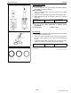
Top Clearance
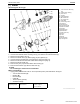
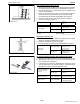
1. Remove the cylinder head.
2. With the piston at TDC, use grease to affix three or four
plastigauges of a diameter 1.5 mm (0.059 in.) x 5.0 to 7.0 mm
(0.20 to 0.27 in.) long to the crown of the piston; keep the
gauges away from the intake valve and combustion chamber
fittings.
3. Take the piston to an intermediate position, install the cylinder
head and tighten the head bolts to the specified torque.
4. Turn the crankshaft so the piston goes through TDC.
5. Remove the cylinder head and measure the thickness of the
plastigauges.
6. If they are out of spec, check the oil clearance of the crank pin
journal and piston pins.
9Y1210785ENS0061US0
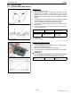
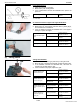
Cylinder Head Surface Flatness
1. Clean the cylinder head surface.
2. Place a straightedge on the cylinder head's four sides and two
diagonal as shown in the figure.
3. Measure the clearance with a thickness gauge.
4. If the measurement exceeds the allowable limit, correct it with a
surface grinder.
IMPORTANT
• Do not place the straightedge on the combustion chamber.
• Be sure to check the valve recessing after correcting.
9Y1210785ENS0062US0
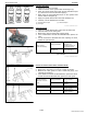
Top clearance Factory specification
0.50 to 0.70 mm
0.020 to 0.027 in.
Tightening torque Cylinder head screw
38 to 42 N·m
3.8 to 4.3 kgf·m
28 to 31 lbf·ft
(1) Plastigauge
(2) Crushed Plastigauge
(3) Scale
Cylinder head surface
flatness
Allowable limit
0.05 mm
0.002 in.
KiSC issued 01, 2013 A